Table of Contents
Advertisement
Advertisement
Table of Contents

Related Manuals for ClearOne BMA CT


Summary of Contents for ClearOne BMA CT
- Page 1 BMA CT Beamforming Mic Array - Ceiling-Tile Quick-Start Guide...
-
Page 2: Table Of Contents
Table of Contents IMPORTANT SAFETY INSTRUCTIONS ......... 1 THE BMA CT .................. 2 QUICK-START OVERVIEW ............3 CONNECTING THE ARRAYS ............4 I/O C ................4 OnneCtIOns ................6 OnneCtIOns UPDATING ARRAY FIRMWARE ............ 8 TESTING THE ARRAYS ..............8 &... -
Page 3: Important Safety Instructions
QUICK-START GUIDE IMPORTANT SAFETY INSTRUCTIONS Read these instructions. Keep these instructions. Heed all warnings. Follow all instructions. Do not use this apparatus near water. Clean only with dry cloth. Do not block any ventilation openings. Install in accordance with the manufacturer’s instructions. -
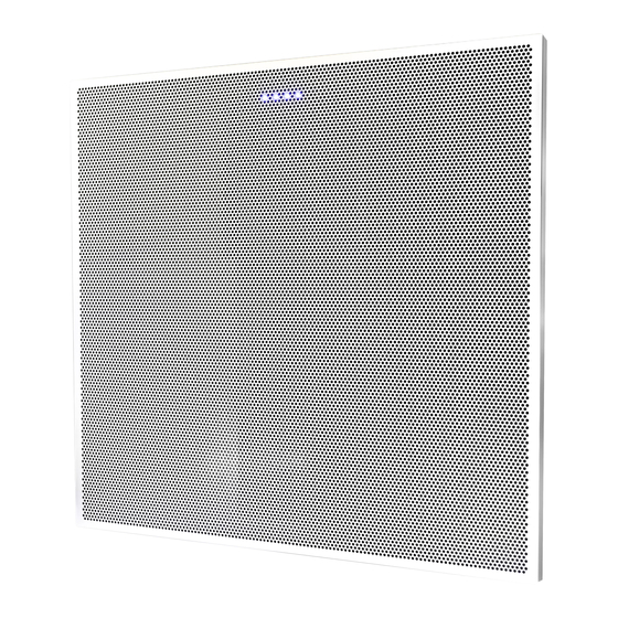
Page 4: The Bma Ct
Beamforming Mic Array systems. The latest version of the CP2 firmware and software can be found on the ClearOne website at: http://www.clearone.com/resource-product-line?pid=1029 The latest version of the BMA CT firmware and Installation Guide can be found on the ClearOne website at: http://www.clearone.com/resource-product-line?pid=1030... -
Page 5: Quick-Start Overview
QUICK-START GUIDE QUICK-START OVERVIEW Installing and using the BMA CT arrays in your CP2 site is subject to the following parameters: The arrays can only be used with CP2 systems. You must have a 128, 128D, 128T, 128TD, 128V, 128VD, 128VT, 128VTD, 120, 48T, 48VT, 48VTD, and/or 48V. -
Page 6: Connecting The Arrays
BMA CT CONNECTING THE ARRAYS Connect the BMA CT units to the CP2 unit via P-Link connections using CAT6-24AWG solid conductor RJ45 cables. i/o c onnectionS Speakers out Power-source selection switch The arrays must be powered by an external PoE source that supports Mode B type power delivery. - Page 7 QUICK-START GUIDE QUICK-START GUIDE ClearOne PoE power supply part number 910-3200-202 is recom- mended, and will power up to three P-Link devices. Some third-party PoE injectors will work, but not all. Mode B PoE injectors that meet the PoE IEEE 802.3at specification should power three devices.
-
Page 8: P-L Ink C Onnections
CONVERGE Pro 2 (Power, Audio, Control) 2 x 10W speakers P-Link Connecting 3 BMA CT units to one CP2 Unit. P-Link cables can vary in length up to 200 ft 2 x 10W speakers BMA CT requires its own PoE (IEEE 802.3at-compliant) - Page 9 QUICK-START GUIDE P-Link CONVERGE Pro 2 (Power, Audio, Control) Up to 200 ft. P-Link Connecting 3 BMA CT units and 3 P-Link Up to 200 ft. compatible devices to one CP2 unit. P-Link Up to 200 ft. P-Link Up to 200 ft.
-
Page 10: Updating Array Firmware
BMA CT UPDATING ARRAY FIRMWARE Connect the P-Link cable between the CP2 units and the arrays. Connect the CP2 units with CONVERGE Pro 2 CONSOLE. Open the Firmware Loader screen. Browse for the BMA_CT_vx.x.x.x.mdo file. Download the array firmware. The array(s) will default and reboot after the download of firmware. -
Page 11: Icrophone Rray Rientation
QUICK-START GUIDE QUICK-START GUIDE icroPhone rray rientation The LED indicators should be oriented in the room according to the beam selection needs for optimal coverage. The diagrams below show the orientation of the LED indicators toward the head of the conference table with the resulting room coverage and beam mapping shown below. -
Page 12: Mounting The Arrays
BMA CT MOUNTING THE ARRAYS Lenum hieLd with eiSmic abLeS If installing both the plenum shield and seismic cables, four slots of approximately 1” length should be cut diagonally in the plenum shielding to match the points of seismic cable attachment. Otherwise, skip this step and go to page 11 for installation of plenum shield only or page 12 for isntallation of seismic cables only. -
Page 13: P Lenum S Hield I Nstallation
QUICK-START GUIDE Lenum hieLd nStaLLation Remove the liner from adhesive in four places on underside of shielding, and thread cables through cut slots before attaching to ceiling. -
Page 14: S Eismic C Ables
(not included). Four attachment points are recommended for stability. If installing with the plenum shield, feed cables thru slots cut in earlier step (see Pg 10). Detailed instructions are included in the BMA CT Installation Guide available on the ClearOne website: http://www.clearone.com/resource-product-line?pid=1030... -
Page 15: Compliance
QUICK-START GUIDE COMPLIANCE Details on compliance can be found on the ClearOne website under “Resource Library”. Part Numbers Item Part No. White BMA CT 24” 910-3200-205 White BMA CT 600mm 910-3200-205-I PoE Power Supply Kit 910-3200-202 50 Ft RJ45 CAT6 Cable... -
Page 16: Isometric Diagrams
BMA CT ISOMETRIC DIAGRAMS Side ViewS back View... -
Page 17: Supported Converge Pro 2
Salt Lake City, UT 84116 TechSupport Tel: 801.975.7200 International Tel: 801.974.3760 Sales: 800.707.6994 Tel: +1.801.975.7200 e-mail: tech.support@clearone. e-mail: global@clearone.com © 2019 ClearOne, Inc. All rights reserved. Information in this document is subject to change without notice. QSG-0074-001 Rev 2.4 Mar 2019...
Need help?
Do you have a question about the BMA CT and is the answer not in the manual?
Questions and answers