Table of Contents
Advertisement
Quick Links
Advertisement
Table of Contents

Related Manuals for Crestron CHV-TSTATRF


Summary of Contents for Crestron CHV-TSTATRF
- Page 1 Crestron CHV-TSTATRF infiNET™ Thermostat Operations & Installation Guide...
- Page 2 This document was prepared and written by the Technical Documentation department at: Crestron Electronics, Inc. 15 Volvo Drive Rockleigh, NJ 07647 1-888-CRESTRON All brand names, product names and trademarks are the property of their respective owners. ©2008 Crestron Electronics, Inc.
-
Page 3: Table Of Contents
Physical Description... 4 Industry Compliance ... 7 Installation ... 8 Mounting the CVH-TSTATRF to the Wall... 8 Wiring the CHV-TSTATRF to the HVAC System ... 10 Basic Setup ... 15 Basic Thermostat Setup... 15 Basic infiNET™ Setup... 16 Advanced Setup ... 19 Setup Mode... -
Page 5: Infinet™ Thermostat: Chv-Tstatrf
Introduction The CHV-TSTATRF is a wireless networked thermostat featuring infiNET™ wireless technology. The CHV-TSTATRF is designed to be installed easily in place of a conventional thermostat without requiring additional control wiring. Although it can be used as a standalone thermostat, the CHV-TSTATRF delivers enhanced functionality as part of a complete Crestron Home communicating via the infiNET wireless control network. - Page 6 In addition, a dedicated repeater (C2N-MNETRPT, sold separately) can be added to increase the system range. NOTE: The CHV-TSTATRF must be powered by 24 Volt AC source and have its power setting on “24” to allow it to function as a repeater.
-
Page 7: Specifications
Crestron CHV-TSTATRF Specifications Specifications for the CHV-TSTATRF are listed in the following table. CHV-TSTATRF Specifications (Continued on following page) Operations & Installation Guide – DOC. 6490A SPECIFICATION Wireless C2N-MNETGW gateway/transceiver required (sold separately) Two-way RF, 2.4 GHz ISM Channels 11-26 RF Transceiver (2400 to 2483.6 MHz),... -
Page 8: Physical Description
(including the FTP site). Physical Description This section provides information on the connections, controls and indicators available on your CHV-TSTATRF. CHV-TSTATRF Physical View 4 • infiNET™ Thermostat: CHV-TSTATRF SPECIFICATION Weight 6.7 oz (189.9 g) Available Models CHV-TSTATRFA... - Page 9 Crestron CHV-TSTATRF CHV-TSTATRF Overall Dimensions (Front and Side Views) MODE CHV-TSTATRF Overall Dimensions (Rear View) Operations & Installation Guide – DOC. 6490A 5.53 in (14.05 cm) 3.27 in (8.30 cm) infiNET™ Thermostat: CHV-TSTATRF • 5 infiNET™ Thermostat 1.03 in (2.60 cm) 4.50 in...
- Page 10 Thermostat CHV-TSTATRF (Connection View, front with cover removed) Connectors, Controls & Indicators 6 • infiNET™ Thermostat: CHV-TSTATRF CONNECTORS, CONTROLS & INDICATORS MODE BUTTON Cycles through available System Modes: OFF, HEAT, EMERGENCY HEAT (for heat pump or dual-fuel systems only), COOL and AUTO.
-
Page 11: Industry Compliance
Crestron CHV-TSTATRF Industry Compliance As of the date of manufacture the CHV-TSTATRF has been tested and found to comply with specifications for CE marking and standards per EMC and Radiocommunications Compliance Labelling. FCC ID: EROCWD1013 Compliance Statement (Part 15.19) This device complies with Part 15 of the FCC Rules. Operation is subject to the following two conditions: Warning (Part 15.21) -
Page 12: Installation
(HVAC industry standard). The following tools/hardware are required for installation. Use the following procedure to install the CHV-TSTATRF in a standard, single-gang electrical box (refer to illustration on the following page): CAUTION: Excess wire that is pinched between the CHV-TSTATRF and electrical box could short out. - Page 13 Crestron CHV-TSTATRF infiNET™ Thermostat Installation view infiNET™ Thermostat: CHV-TSTATRF • 9 Operations & Installation Guide – DOC. 6490A...
-
Page 14: Wiring The Chv-Tstatrf To The Hvac System
Thermostat Wiring the CHV-TSTATRF to the HVAC System Make the necessary connections as called out in the illustrations that follow. A flat head screwdriver (not supplied) is required to attach the control wires from the HVAC system. Apply power after all connections have been made. - Page 15 Crestron CHV-TSTATRF CHV-TSTATRF in Heat Only Application CHV-TSTATRF in Heat Only with Fan Application RH-RC jumper required since supply power is returned through RH NOTE: To run fan during heat calls, be sure to enable the HF parameter by setting it to “Y”.
- Page 16 Thermostat CHV-TSTATRF in Cool Only Application RH-RC jumper required since supply power is returned through RH CHV-TSTATRF in Heat-Cool Application with Separate Systems 12 • infiNET™ Thermostat: CHV-TSTATRF Optional, for power Optional, for power Compressor Operations & Installation Guide – DOC. 6490A Crestron CHV-TSTATRF (Refer to “Basic Thermostat...
- Page 17 (e.g. Crestron’s C2N-RTHS, sold separately) to function properly. In SIMPL Windows, connect the “Temp” output of the sensor to the “OutdoorTemp” input of the CHV-TSTATRF. For details, refer to the SIMPL Windows help file. If using D3 Pro or SystemBuilder refer to “Programming with Crestron D3 Pro or SystemBuilder”...
- Page 18 Thermostat CHV-TSTATRF in Dual-Fuel Heat Pump Application Optional, for power NOTE: The diagram above applies where furnace control is not integrated into the heat pump system. 14 • infiNET™ Thermostat: CHV-TSTATRF Crestron CHV-TSTATRF (Refer to “Basic Thermostat Setup” on page 15)
-
Page 19: Basic Setup
Heat Pump (dF) functions. Then press MODE repeatedly until the Power Source function is displayed (Po). By default, the CHV-TSTATRF is configured to be powered by two AA alkaline batteries. In addition, in order to extend battery life, the device is able to steal power from the HVAC system by drawing a small amount of current through the heat or cool terminals. -
Page 20: Basic Infinet™ Setup
10 minutes. Basic infiNET™ Setup The MNET ID of the CHV-TSTATRF has been factory set to 01. After an infiNET device is added to an infiNET network, its MNET ID must be changed to a value that can be addressed by the control system program (03 to 20). The MNET IDs of multiple CHV-TSTATRF devices on the same gateway must be unique. - Page 21 ACQUIRE on the gateway. Refer to the latest revision of the C2N-MNETGW guide (Doc. 6317). To exit from Setup mode, press the FAN button on the CHV-TSTATRF. The Fan icon will indicate the status of infiNET communication: Operations & Installation Guide – DOC. 6490A to choose 11 –...
- Page 22 Verify that the MNET ID for the infiNET device is set to match the MNET ID specified in the program. Check the D3 Pro, SystemBuilder or SIMPL Windows program to ensure that a CHV-TSTATRF has been added at the proper MNET-ID. Refer to “Programming with Crestron D3 Pro or SystemBuilder”...
-
Page 23: Advanced Setup
Advanced Setup Setup Mode After the CHV-TSTATRF is installed, it is necessary to set it up for a particular heating/cooling system. Please note that some of the setup parameters listed below will not always be available. Refer to “Setup Mode Parameters/Functions”, which starts on page 20 for details. -
Page 24: Setup Mode Parameters/Functions
(refer to “LCD Display” which starts on page 28). NOTE: While in Setup mode, a period of one minute with no button activity will cause the CHV-TSTATRF to revert to standard operation, unless a function (such as an infiNET acquire) is executing. - Page 25 5 tenths degree increments Enabled (Y) or Disabled (no) Enabled (Y) or Disabled (no) infiNET™ Thermostat: CHV-TSTATRF • 21 infiNET™ Thermostat NOTES Lower setting results in more frequent cycles and faster response (tighter regulation). Higher setting results in less frequent cycles and slower response (looser regulation).
- Page 26 Version infiNET ID (MNET ID) infiNET RF Channel infiNET Sleep Time Start infiNET Acquire Unacquire Gateway (Continued on following page) 22 • infiNET™ Thermostat: CHV-TSTATRF DEFAULT VALID VALUES VALUE 24V always available (24) or steal power (SP) Firmware version is displayed in xx.yy.zz...
- Page 27 In progress (flashing --) Finished, self test ok (00) Finished, self test failed (E#, where # represents an error code) infiNET™ Thermostat: CHV-TSTATRF • 23 infiNET™ Thermostat NOTES Gives estimated remaining battery life in percent. Restores all setup parameters to their default settings.
-
Page 28: Operation
Thermostat Operation System Mode The MODE button on the CHV-TSTATRF will cycle the unit through all available system modes in the following order: Off, Heat, Emergency Heat (for heat pump and dual-fuel systems), Cool and Auto (if enabled in Setup). - Page 29 Smaller values for the Auto Dead Band setting will result in tighter temperature regulation but more frequent cycling between heating and cooling. NOTE: When using a single setpoint, the CHV-TSTATRF has a 20-minute change limiter to prevent system toggling.
-
Page 30: Fan
For example, in the winter they may want to lower the heat setpoint while they sleep to lower heating costs. To accommodate this, the CHV-TSTATRF provides a “Scheduled Heat Setpoint” and a “Scheduled Cool Setpoint” which can be specified by the control system program. This is handled automatically by the “Crestron CHV-TSTATRF w/5-2 Scheduler”... -
Page 31: Remote Operation
Instead, the thermostat will wake up approximately 10 seconds after the last button press to send its updated status to the control system. NOTE: When the CHV-TSTATRF is powered via a constant 24 VAC supply, it will not go to sleep. -
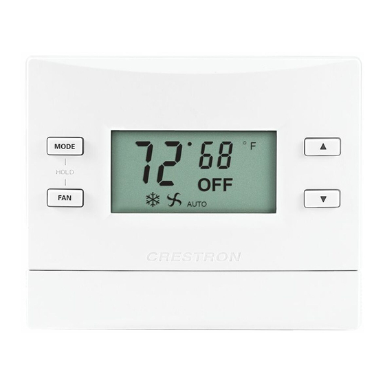
Page 32: Lcd Display
Thermostat LCD Display CHV-TSTATRF LCD Display LCD Display Elements (Continued on following page) 28 • infiNET™ Thermostat: CHV-TSTATRF AUTO LCD DISPLAY ELEMENT Large seven-segment Indicates current ambient temperature digits Setup mode, indicates current setup parameter/function. Display range is limited to –9º to 99ºF (-9º to 43ºC). - Page 33 LCD Display Elements (Continued) 1. For heat pump and dual-fuel systems, when you select Emergency Heat mode (by pressing and 2. When the CHV-TSTATRF detects a low battery condition (approximately one month of battery life Operations & Installation Guide – DOC. 6490A...
-
Page 34: Programming Software
CHV-TSTATRF. Programming with SIMPL Windows NOTE: While SIMPL Windows can be used to program the CHV-TSTATRF, it is recommended to use SystemBuilder or D3 Pro for configuring a system. SIMPL Windows is Crestron’s premier software for programming Crestron control systems. - Page 35 Locating the CHV-TSTATRF in the Device Library C2Net Device, Slot 9 Operations & Installation Guide – DOC. 6490A NOTE: It is not recommended to add the CHV-TSTATRF directly. Instead, add one of the available “modules” listed underneath it as shown below.
-
Page 36: Example Program
Detail View. Each signal in the symbol is described in the SIMPL Windows help file (F1). Example Program An example program for the CHV-TSTATRF is available from the Crestron website (http://www.crestron.com/exampleprograms). 32 • infiNET™ Thermostat: CHV-TSTATRF •... -
Page 37: Uploading And Upgrading
Finally, program checks can be performed (such as changing the device ID) to ensure proper functioning. Establishing Communication Use Crestron Toolbox for communicating with the CHV-TSTATRF; refer to the Crestron Toolbox help file for details. There is a single method of communication: indirect serial communication. -
Page 38: Program Checks
FTP site.) Upgrade CHV-TSTATRF firmware via Crestron Toolbox. Since the CHV-TSTATRF might be “asleep”, there may be a delay of one minute or less before the update starts. -
Page 39: Problem Solving
It should look for the gateway within 10 seconds. Check circuit breaker. Check for +24V on C connector. Check circuit breaker powering furnace or boiler. Recheck wiring connections. Check batteries, replace if necessary. infiNET™ Thermostat: CHV-TSTATRF • 35... -
Page 40: Bootloader
The bootloader is a low-level version of the CHV-TSTATRF’s firmware that will become active in the event an upload of the standard firmware fails. This lets you perform some basic functions with the goal of getting the CHV-TSTATRF back to normal operation. -
Page 41: Reference Documents
(refer to “Setup Mode” which starts on page 19). From the bootloader, Setup mode will support only the following functions: To restore functionality, try cycling power to the CHV-TSTATRF. If unit remains in bootloader, you should resend the latest firmware using Crestron Toolbox. -
Page 42: Appendix: About Heat Pumps
A dual-fuel type setting (dF) will not allow both systems to run at the same time. 38 • infiNET™ Thermostat: CHV-TSTATRF Crestron CHV-TSTATRF Operations & Installation Guide – DOC. 6490A... -
Page 43: Glossary
An air-handling device for moving air in a distribution system. A call is the action taken by the thermostat when it sends a signal to turn on the heating or cooling system. A heat pump used in conjunction with an existing fossil fueled furnace. - Page 44 Run Fan in Heat Calls Setpoint Time Delay (Timer Guards) 40 • infiNET™ Thermostat: CHV-TSTATRF The total amount of moisture in air. Relative humidity (RH) is the amount of moisture in air, relative to its total capability based upon its temperature (dew point).
-
Page 45: Return And Warranty Policies
All brand names, product names and trademarks are the sole property of their respective owners. Windows is a registered trademark of Microsoft Corporation. Windows95/98/Me/XP/Vista and WindowsNT/2000 are trademarks of Microsoft Corporation. Operations & Installation Guide – DOC. 6490A infiNET™ Thermostat infiNET™ Thermostat: CHV-TSTATRF • 41... - Page 46 Thermostat Crestron CHV-TSTATRF This page is intentionally left blank. 42 • infiNET™ Thermostat: CHV-TSTATRF Operations & Installation Guide – DOC. 6490A...
- Page 47 Crestron CHV-TSTATRF infiNET™ Thermostat This page is intentionally left blank. infiNET™ Thermostat: CHV-TSTATRF • 43 Operations & Installation Guide – DOC. 6490A...
- Page 48 Crestron Electronics, Inc. Operations & Installation Guide – DOC. 6490A 15 Volvo Drive Rockleigh, NJ 07647 (2015101) Tel: 888.CRESTRON 11.08 Fax: 201.767.7576 Specifications subject to www.crestron.com change without notice.
Need help?
Do you have a question about the CHV-TSTATRF and is the answer not in the manual?
Questions and answers