
Related Manuals for Advantech DLoG MTC 6 Series


Summary of Contents for Advantech DLoG MTC 6 Series
- Page 1 Industrial PCs applied in Logistics and Warehouse Heavy Duty Fleet Management Stationary and Automation DLoG MTC 6 Series Version 2.0...
- Page 2 © Copyright 2010 - 2012 Technical customer support DLoG GmbH If you experience technical difficulties, Industriestraße 15 please consult your distributor or contact D-82110 Germering the technical services department at Germany Advantech-DLoG’s headquarters: All rights reserved (+49) 89 / 41 11 91 0 www.advantech-dlog.com...
-
Page 4: Table Of Contents
Transmission of radio frequencies ................10 2.8. Clean / maintain industrial PC ................. 11 2.9. Modifications and repairs only by Advantech-DLoG ..........11 2.10. CE Marking ......................12 2.11. RTTE Directive 1999/5/EC .................. 13 ... - Page 5 3.4.5. Serial port ......................20 3.4.6. USB, Service USB ................... 20 3.4.7. LCD interface ....................21 3.4.8. Touch interface ....................21 3.4.9. Network interface .................... 21 3.4.10. Sound (integrated speaker) ................. 22 ...
- Page 6 5.6.2. Power supply cables ..................48 5.6.3. MTC 6 supply cable ..................49 5.7. Service USB interface ....................50 5.8. Connecting external devices ..................51 5.9. Powering up the MTC 6 ................... 52 ...
- Page 7 8.3. Operating states ...................... 68 Operating system ................. 69 9.1. Pre-installed on Flash ....................69 9.2. Installing on Flash ....................69 Touch screen ..................70 10.1. Construction type and resistance ................ 70 ...
- Page 8 Common mistakes in usage ............ 3 0 6 H 1 5.1. Power supply ....................... 1 3 0 H 3 0 7 H 1 5.2. Powering up/down .................... 1 3 1 H 3 0 8 H 1 5.3.
- Page 9 List of figures Figure 3.1: 15” model MTC 6 series ................. 16 Figure 3.2: Speaker (MTC 6 back) ................... 22 Figure 3.3: Voice Kit handset microphone (optional) ............22 Figure 3.4: Integrated antenna ..................23 Figure 3.5: Remote antenna ..................... 23 ...
- Page 10 Figure 5.11: Service USB under the antenna cap ............50 Figure 5.12: MTC 6 <Power>-key ..................52 Figure 6.1: SMALL keyboard .................... 53 Figure 6.2: 24-key keypad ....................53 Figure 7.1: Position of the ground bolt ................58 ...
-
Page 11: About This Manual
Please take note of all documentation received for your industrial PC, such as safety information, assembly instructions, etc. 1.2. Current information on the internet Current manuals and additional useful information can be found on the internet at www.advantech-dlog.com. MTC 6 Series User’s Manual V2.00... -
Page 12: For Qualified Personnel
About this manual 1.3. For qualified personnel This manual was written for qualified personnel. The information is intended exclusively to complement the expertise of qualified personnel , not to replace it. 1.4. Keep this manual Please keep this manual in a safe place. It should always be at hand near the described device. - Page 13 About this manual Hints This symbol indicates hints that help you to understand how to use the product or the manual. Lists and Instructions Lists and instructions are indicated with bullet points or numbers, for example: • Power pack • Cable Methods for emphasis Any other emphasized text elements are highlighted in bold or underlined.
-
Page 14: Basic Safety Guidelines
Basic safety guidelines 2. Basic safety guidelines • Please read and follow these safety instructions. • Do not throw them away. 2.1. Always install, operate, and maintain the unit properly The MTC 6 was designed and built according to modern technology and accepted safety regulations. -
Page 15: Preventing Electrical Hazards
Basic safety guidelines Area of application: not for use in life-support systems or critical safety systems The device is not designed for use in life-support systems or critical safety systems where system malfunction can lead to the direct or indirect endangerment of human life. The operator shall take full responsibility for using the device in these situations. - Page 16 Advantech-DLoG power cables meet the specific requirements for low-temperature flexibility, UV resistance, oil resistance, etc. • Use only original power supply cables from Advantech-DLoG. If other power supply cables are used: • The user/operator of the industrial PC is solely responsible for the resulting damage.
-
Page 17: When Mounting Please Note The Following
Basic safety guidelines Do not use industrial PCs in locations where flammable gases or vapors are present The operation of electrical equipment in explosive environments can be dangerous. • Turn off the industrial PC when you are near gas stations, fuel depots, chemical plants or places where blasting operations take place. - Page 18 Basic safety guidelines Deployment location: Note IP protection class and permissible ambient conditions The permissible ambient conditions are described in the manual for your industrial PC (chapter Fehler! Verweisquelle konnte nicht gefunden werden. Fehler! Verweisquelle konnte nicht gefunden werden.). Before use: Install cable cover Ensuring the IP protection of industrial PCs: •...
-
Page 19: Connect / Disconnect External Devices
Only use authorized accessories • Only use the cables, power packs and other accessories that have been tested and approved for the respective industrial PC by DLoG GmbH. • Ask your Advantech-DLoG sales representative about authorized accessories. MTC 6 Series User’s Manual V2.00... -
Page 20: Transmission Of Radio Frequencies
Basic safety guidelines 2.7. Transmission of radio frequencies Note the permitted transmission power The maximum permitted transmission power for the respective country must not be exceeded. Responsibility for this lies with the operator of the industrial PC. Installation note: Keep a minimum distance of 20 cm between individuals and antennas To ensure that the limits set by the FCC for exposure to radio waves are not exceeded:... -
Page 21: Clean / Maintain Industrial Pc
Do not carry out any repairs on the industrial PC yourself. • Always contact the responsible technical service officer at Advantech-DLoG and send in your unit for repair if necessary. • Refer to the nameplate on the back of the unit for important technical service information. -
Page 22: Ce Marking
Basic safety guidelines 2.10. CE Marking Remark for CE class A products: Class A products may be used in residential environment but with the condition that the end user is informed about the possible consequence with a warning information in the user manual: Warning! This is a class A device. -
Page 23: Rtte Directive 1999/5/Ec
Basic safety guidelines 2.11. RTTE Directive 1999/5/EC With regard to the RTTE Directive 1999/5/EC the statements in the declaration of conformity for the MTC 6 (see page 2 of this manual) apply. Česky Toto zařízení je v souladu se základními požadavky a ostatními [Czech]: odpovídajícími ustanoveními Směrnice 1999/5/EC. -
Page 24: Special Rule/Restriction
Basic safety guidelines Malti Dan l-apparat huwa konformi mal-ħtiġiet essenzjali u l- [Maltese]: provedimenti l-oħra rilevanti tad-Direttiva 1999/5/EC. Ez a készülék teljesíti az alapvető követelményeket és más Magyar 1999/5/EK irányelvben meghatározott vonatkozó [Hungarian]: rendelkezéseket. Norsk Dette utstyret er i samsvar med de grunnleggende krav og Norwegian]: andre relevante bestemmelser i EU-direktiv 1999/5/EF. -
Page 25: Fcc User Information
Basic safety guidelines 2.12. FCC user information Declaration of the Federal Communications Commission This equipment has been tested and found to comply with the limits for a Class A digital device, pursuant to Part 15 of the FCC Rules and meets all requirements of the Canadian Interference-Causing Equipment Standard ICES-003 for digital apparatus. -
Page 26: Device Description - Technical Specifications
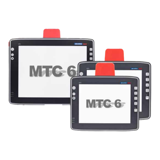
Device description – Technical specifications 3. Device description – Technical specifications Thank you for choosing the MTC 6. Figure 3.1: 15” model MTC 6 series 3.1. Device models This manual applies to the following models of the MTC 6: • MTC 6 with 10.4“ display •... -
Page 27: Abbreviations Used For Devices And Accessories
1.1 GHz Clock rate of the CPU S/N ..12 digit serial number composed of: • Advantech-DLoG specific device code (41 stands for the MTC 6 model range) • Week and year of manufacture • Six digits for identification MTC 6 Series... -
Page 28: Technical Specifications
Device description – Technical specifications 3.4. Technical specifications 3.4.1. CPU, Cache, RAM CPU and Chipset combinations: Chipset Intel® Atom™ processor Z510 1.1 GHz, 400 MHz FSB Cache and 400 MHz memory bus speed, 512 k L2 cache, 45 nm Chipset Intel® SCH US15W 1 GB RAM DDR2-Technology BIOS... -
Page 29: Housing - Mechanical
Device description – Technical specifications 3.4.2. Housing - Mechanical Material Rugged aluminum-cast housing with integrated heat sink Protection class IP 65, IP 66 und IP 67 ESD safe Weight 10.4“ : 3.0 kg 12.1“ : 3.5 kg 15.0“: 4.9 kg Dimensions See Chapter 3.5 Dimensions 3.4.3. -
Page 30: Operating Systems (Optional)
Device description – Technical specifications 3.4.4. Operating systems (optional) Microsoft Windows XP Professional ® ® Windows XP Embedded ® Windows Embedded Standard 7 ® Linux CENT OS 5.x Generic with Gnome 3.4.5. Serial port COM1 Serial port Max. 115.200 Baud (16550A compatible, 16 byte FIFO), supports RS-232 on an external 9pin D-Sub connection ESD level 4 protected (acc. -
Page 31: Lcd Interface
Device description – Technical specifications 3.4.7. LCD interface VGA controller Intel Graphics Media Accelerator 500 (Intel GMA 500), ® ® up to 256 MByte frame buffer supporting Direct X 9.0E and Open GL 2.0 Shared Memory architecture Resolution up to 1366 x 768 pixels Up to 24 bit color depth, depending on which LCD is used 3.4.8. -
Page 32: Sound (Integrated Speaker)
Device description – Technical specifications 3.4.10. Sound (integrated speaker) MTC 6 devices have an integrated speaker. Speaker Figure 3.2: Speaker (MTC 6 back) 3.4.11. Voice Kit (optional) The optional MTC 6 Voice Kit includes a handset microphone incl. a speaker system and mounting bracket. -
Page 33: Integrated Wlan Antenna (Optional)
Device description – Technical specifications 3.4.12. Integrated WLAN antenna (optional) Gain (without cable lost): 3 dBi max. Frequency band: 2400 to 2485 MHz / 5150 to 5875 MHz Impedance: 50 Ω VSWR (voltage standing-wave ratio): < 2 Figure 3.4: Integrated antenna Polarization: vertical Max. -
Page 34: Power Supply
Device description – Technical specifications 3.4.14. Power supply The device model/power supply type is displayed on the device type plate. 12/24 VDC nominal DC power pack 12/24 VDC Voltage range: 9 to 36 VDC 30 W internal The 12/24VDC power supply can provide the full output power Type DC-11 and for 20 seconds in a voltage range of 6 to 9 VDC. - Page 35 Device description – Technical specifications Power consumption MTC 6/10: typically 20 W Power consumption Power consumption MTC 6/12: typically 25 W Power consumption MTC 6/15: typically 25 W Standby typically 1 W (valid for all MTC 6 devices) The SELV circuit is a secondary circuit that is designed and protected so that its voltages will not exceed a safe value both when operating correctly or if a single error occurs.
-
Page 36: Test Marks
Device description – Technical specifications 3.4.15. Test marks See page 2 of this manual: Declaration of Conformity MTC 6. 3.4.16. Ambient conditions -30° to +50° C Operating temperature In accordance with EN 60068-2-1/2 Storage -30° to +65 °C temperature In accordance with EN 60068-2-1/2 Relative humidity 10% to 90% @ 40°C non-condensating In accordance with EN 60068-2-3... -
Page 37: Dimensions
Device description – Technical specifications 3.5. Dimensions 3.5.1. MTC 6/10 Front view Dimensions without add-ons (in mm): Figure 3.6: Dimensions MTC 6/10 front view MTC 6 Series User’s Manual V2.00... -
Page 38: Figure 3.7: Dimensions Mtc 6/10 Side View
Device description – Technical specifications Side view Dimensions without add-ons (in mm): Figure 3.7: Dimensions MTC 6/10 side view User’s Manual V2.00 MTC 6 Series... -
Page 39: Figure 3.8: Dimensions Mtc 6/10 Top View
Device description – Technical specifications Top view Dimensions without add-ons (in mm): Figure 3.8: Dimensions MTC 6/10 top view MTC 6 Series User’s Manual V2.00... -
Page 40: Mtc 6/12
Device description – Technical specifications 3.5.2. MTC 6/12 Front view Dimensions without add-ons (in mm): Figure 3.9: Dimensions MTC 6/12 front view User’s Manual V2.00 MTC 6 Series... -
Page 41: Figure 3.10: Dimensions Mtc 6/12 Side View
Device description – Technical specifications Side view Dimensions without add-ons (in mm): Figure 3.10: Dimensions MTC 6/12 side view MTC 6 Series User’s Manual V2.00... -
Page 42: Figure 3.11: Dimensions Mtc 6/12 Top View
Device description – Technical specifications Top view Dimensions without add-ons (in mm): Figure 3.11: Dimensions MTC 6/12 top view User’s Manual V2.00 MTC 6 Series... -
Page 43: Mtc 6/15
Device description – Technical specifications 3.5.3. MTC 6/15 Front view Dimensions without add-ons (in mm): Figure 3.12: Dimensions MTC 6/15 front view MTC 6 Series User’s Manual V2.00... -
Page 44: Figure 3.13: Dimensions Mtc 6/15 Side View
Device description – Technical specifications Side view Dimensions without add-ons (in mm): Figure 3.13: Dimensions MTC 6/15 side view User’s Manual V2.00 MTC 6 Series... -
Page 45: Figure 3.14: Dimensions Mtc 6/15 Top View
Device description – Technical specifications Top view Dimensions without add-ons (in mm): Figure 3.14: Dimensions MTC 6/15 top view MTC 6 Series User’s Manual V2.00... -
Page 46: Vesa Drill Holes
Device description – Technical specifications 3.6. VESA drill holes 3.6.1. MTC 6/10 Dimensions without add-ons (in mm): Figure 3.15: Position of the VESA drill holes MTC 6/10 User’s Manual V2.00 MTC 6 Series... -
Page 47: Mtc 6/12
Device description – Technical specifications 3.6.2. MTC 6/12 Dimensions without add-ons (in mm): Figure 3.16: Position of the VESA drill holes MTC 6/12 MTC 6 Series User’s Manual V2.00... -
Page 48: Mtc 6/15
Device description – Technical specifications 3.6.3. MTC 6/15 Dimensions without add-ons (in mm): Figure 3.17: Position of the VESA drill holes MTC 6/15 User’s Manual V2.00 MTC 6 Series... -
Page 49: Unpacking The Device
Unpacking the device 4. Unpacking the device 4.1. Scope of delivery The delivery includes at least the following: • MTC 6 • Cable cover • Optionally ordered assembly set • Optionally ordered accessories Please verify the delivery contents immediately on receipt! 4.2. -
Page 50: Initial Operation
Initial operation 5. Initial operation WARNING Before operating the unit for the first time, carefully read the Basic safety guidelines at the start of this manual. Configure the MTC 6 before fastening it to machines or vehicles. Software configuration for the WLAN, shutdown automation, etc. is significantly simpler and more convenient on the desktop. -
Page 51: Dlog Config: Front Keys, Automatic Switch-Off
• Turning the MTC 6 on and off together with the vehicle ignition (automatic switch-off) Figure 5.1: DLoG Config Program Menu You can find detailed information in the user manual for the DLoG Config program in our Download Center (www.advantech- dlog.com). MTC 6 Series User’s Manual V2.00... -
Page 52: Wlan Settings
Initial operation 5.2. WLAN settings The settings and access data form must be defined for radio networks like WLAN depending on the optional equipment and intended use of the MTC 6. WARNING Please pay attention to all Basic safety guideline for WLAN. 5.2.1. -
Page 53: Antenna Solutions For Use In Germany
Initial operation 5.2.2. Antenna solutions for use in Germany The integrated Advantech-DLoG antenna solutions are based on the prevailing IEEE 802.11 standard. This standard allows wireless data transfer at rates from 1 Mbps to 54 Mbps using the 2.4 GHz and 5 GHz frequency band (300 Mbps if using IEEE 802.11n). -
Page 54: Summit Client Utility For Wlan Configuration
Initial operation 5.2.3. Summit Client Utility for WLAN configuration The Summit Client Utility (called "SCU" below) is used to set up the WLAN configuration for the MTC 6. WARNING WLAN configurations may only be modified by qualified IT technical staff. Start the SCU with a double press on the SCU icon on the desktop: Figure 5.3: Summit Client Utility Icon Alternatively, you can also start the SCU with one of the following procedures:... -
Page 55: Figure 5.5: Summit Client Utility Menu
Initial operation 5.2.3.1. Password SCU Depending on the configuration, it may be necessary to enter a password. Figure 5.5: Summit Client Utility menu 1. To do so, click the Admin Login button. An input field appears for the password. Figure 5.6: Summit Client Utility password input The standard password is: SUMMIT (must be entered in capital letters!) You can find details about the configuration parameters in the SCU online help. -
Page 56: Calibrate / Re-Calibrate The Touch Screen
Initial operation 5.3. Calibrate / re-calibrate the touch screen Read chapter 10.5 Recalibration with UPDD. 5.4. Protecting the TFT display from the memory effect The TFT display of the MTC 6 has to be protected from the burning in of a motionless image. -
Page 57: External Connectors
Initial operation 5.6. External connectors Connectors on the rear side of the MTC 6: Figure 5.7: External connectors with optional ext. antenna Detail view: Figure 5.8: External connectors detail view (with ext. antenna) MTC 6 Series User’s Manual V2.00... -
Page 58: Dc Voltage Supply Connector
Advantech-DLoG power cables meet the specific requirements for low-temperature flexibility, UV resistance, oil resistance, etc. • Use only original power supply cables from Advantech-DLoG. If other power supply cables are used: • The user/operator of the industrial PC is solely responsible for the resulting damage. -
Page 59: Mtc 6 Supply Cable
Initial operation 5.6.3. MTC 6 supply cable DC+ ; blue or grey wire Figure 5.10: Power supply cable MTC 6 Series User’s Manual V2.00... -
Page 60: Service Usb Interface
Initial operation 5.7. Service USB interface A service USB interface is arranged under the antenna cap of the MTC 6. Please observe the following information: • Chapter 7.8 Antenna cap and service USB interface The service USB interface may only be used for maintenance purposes, e.g. -
Page 61: Connecting External Devices
Initial operation 5.8. Connecting external devices The MTC 6 must be disconnected from the power supply: • before external devices (e.g., scanner, keyboard) are connected or disconnected • and before the MTC 6 can be connected to a network. All connections and interfaces on the MTC 6 are located on the underside of the unit. Make sure that external peripheral devices with their own power supply are switched on at the same time as the MTC 6 or after you start the MTC 6. -
Page 62: Powering Up The Mtc 6
Initial operation 5.9. Powering up the MTC 6 Only power up the MTC 6 after connecting all of the devices. The MTC 6 is powered up by connecting it to an appropriate power supply and then, depending on the version of the device, either using the <Power>-key or the ignition signal. -
Page 63: Accessories
Accessories 6. Accessories 6.1. Keyboard On the MTC 6 any USB keyboard can be connected. SMALL keyboard A mountable SMALL keyboard with protection class IP 65(German/English) is available for the MTC 6. Figure 6.1: SMALL keyboard 24-key keypad A 24-key keypad which can be mounted onto the device, with a protection class IP 65 is available for the MTC 6. -
Page 64: Mouse
Accessories 6.3. Mouse Any USB mouse or any mouse with RS-232 port can be connected to the MTC 6. 6.4. External CD/DVD-ROM drive An external CD/DVD-ROM drive is available for the MTC 6. This is connected via the USB interface. When connecting an external USB CD/DVD-ROM drive which has its own external power supply the MTC 6 must be disconnected from the power supply. -
Page 65: Usb Recovery Stick
Accessories 6.6. USB recovery stick With the optional Advantech-DLoG recovery stick, images can be backed up and restored on the MTC 6 if necessary (backup & recovery). Please consult your Advantech- DLoG sales representative if necessary. 6.7. Scanners You can connect scanners to either the USB port or the serial port. If connected to COM1, the scanner can be powered through the port (optional, 5 V). -
Page 66: Mounting
Mounting 7. Mounting 7.1. Pay careful attention to mounting instructions Please follow the mounting instructions included with assembly kit when installing your MTC 6. WARNING The unit could fall during transit or installation/mounting and cause injury. Always ensure that there are two persons available when installing or removing the device. -
Page 67: Power Supply
Advantech-DLoG power cables meet the specific requirements for low-temperature flexibility, UV resistance, oil resistance, etc. • Use only original power supply cables from Advantech-DLoG. If other power supply cables are used: • The user/operator of the industrial PC is solely responsible for the resulting damage. -
Page 68: Vehicle Applications (Such As Forklifts)
Mounting 7.4. Vehicle applications (such as forklifts) 7.4.1. Electrical installation Pay special attention to the various electrical potentials when installing the unit on a vehicle (such as a forklift). On the MTC 6, the logic ground and the shield ground are firmly linked. The “logic ground”... - Page 69 Mounting • The other end of the yellow-green supply voltage cable should be connected to the vehicle’s chassis. • Make sure that the MTC 6’s connecting cable is attached as close to the battery as possible. Connecting the MTC 6 to large electrical loads, such as converters for the forklift motor may result in random restarts, malfunctions and/or irreparable damage to the device.
-
Page 70: Position Of The Mtc 6 In The Vehicle
Mounting 7.4.2. Position of the MTC 6 in the vehicle In the vehicle, the driver's field of view must be kept free. If a keyboard and scanner should be installed on the MTC 6, please plan sufficient space. No part of the MTC 6 system may project beyond the vehicle. The MTC 6 may not project outside the vehicle! Figure 7.2: Position of the MTC 6 on a forklift... -
Page 71: Cable Cover (Splash Guard)
Protection class In order to comply with the certified protection class, please use the optionally available assembly kit from Advantech-DLoG. Please observe the installation instructions included with this assembly kit. 7.6. Strain relief After the MTC 6 and bracket are fastened: •... -
Page 72: Minimum Distance To Wlan Antenna
Mounting 7.7. Minimum distance to WLAN antenna In order to avoid exceeding the limits determined by the FCC for exposure to radio waves, you (and other people in your vicinity) should maintain a minimum distance of 20 cm from the antenna integrated into the computer. -
Page 73: Figure 7.4: Opened Antenna Cap
Mounting To access this Service USB interface, you need to remove the antenna cap from the unit. Incorrect or improper removal and fastening of the antenna cap can NOTICE: impair the function of the entire MTC 6 system and in particular the Property WLAN functionality! Incorrect or improper changes made to the damage... - Page 74 Mounting Unfasten antenna cap from unit and refasten it: 1. Unscrew the two screws from the antenna cap with an Allen key (size 3 mm). 2. Lift the antenna cap carefully to avoid pulling on the antenna connection cables (max. 2 to 3 cm). 3.
-
Page 75: Operation
Operation 8. Operation 8.1. Touch Screen Keep the panel surface clean. Prevent any kind of adhesive applied on the surface. Avoid high voltage and/or static charge. Touch screens may not be operated with ball-point pens or writing utensils, tools of any kind (e.g. screwdrivers) or with sharp objects NOTICE: (knives, scalpels, etc). -
Page 76: Front Keys And Leds
Operation 8.2. Front keys and LEDs The MTC 6 has the following front keys and LEDs: <Power> key Special keys Manual brightness control <Shift> key LEDs Figure 8.1: MTC 6 front keys and LEDs 8.2.1. <Power> key and brightness control <Power>-key: Start/Shutdown MTC 6 Manual brightness control: brighter Manual brightness control: darker... -
Page 77: Leds
Operation 8.2.2. LEDs Temp (red) LED indicates an excessively high or low temperature inside the unit Activity (green) LED indicates access of the flash drive Power (green) LED indicates an available internal power supply 8.2.3. Special keys Special keys <S1> to <S8> The special keys can be configured with the “DLoG Config program”... -
Page 78: Operating States
Operation 8.3. Operating states The following operating states are possible for the MTC 6: Status of internal LEDs Power (green) Temp (red) MTC 6 status Initial state, idle time - waiting for a new ignition signal after switch-off; no power supply FLASHING Temperature sensor malfunctioning FLASHING... -
Page 79: Operating System
Operating system 9. Operating system 9.1. Pre-installed on Flash When a MTC 6 with a pre-installed operating system is started, this operating system is loaded following the BIOS boot messages. System-specific device drivers – such as those for graphic, sound, network and touch screens – are also pre-installed. In MTC 6 units with a pre-installed operating system, the system is located on the C partition. -
Page 80: Touch Screen
Touch screen 10. Touch screen 10.1. Construction type and resistance • Analog-resistive touch technology • Construction: Film-Glass (FG) • Hardness of surface: 3H (ASTM D3363) • Resistance : >10 million actuations 10.2. Operation The finger or a suitable stylus can be used for operation. For more details, please see Chapter 8 Operation. -
Page 81: Calibrating The Touch Screen
Carry out the installation of the UPDD tool by starting the Setup.exe file. After the installation: • the touch driver is installed • the touch screen is calibrated (as per Advantech-DLoG standards: 9 point calibration; 10% clearance) • the MTC 6 does not have to be restarted 10.5. -
Page 82: Serial Port
Serial port 11. Serial port The MTC 6 is equipped with an externally accessible serial interface COM1. Resources for the serial port are pre-defined in the system architecture and automatically managed by the BIOS. 11.1. COM1 as a power supply (optional) The COM1 port can optionally supply externally connected equipment with +5 V of power. -
Page 83: Tips & Tricks
Serial port Please note that you have to configure the scanner correctly to NOTICE: RS-232 and the above set BAUDrate following the scanner Property manufacturer’s guidelines. Otherwise the software wedge will not damage function properly. 11.4. Tips & tricks Note that according to the EIA-232-E specification, the maximum cable length is 15 m at 19,200 bps. -
Page 84: Internal Devices
12.3. Onboard sound controller The MTC 6 is equipped with an onboard sound controller. This control the audio output via the internal speaker, or the speech input and output if the Advantech-DLoG Sound Kit (optional) is connected. User’s Manual V2.00 MTC 6 Series... -
Page 85: Network Adapter (10/100/1000)
Internal devices 12.4. Network adapter (10/100/1000) The MTC 6 is equipped with a 10/100/1000 Mbit network adapter. This adapter can be accessed via the bottom of the device and offers an RJ45 connection jack. The RJ45 connection port features two integrated status LEDs. They display the following messages: Left LED (green) Right LED (orange):... -
Page 86: Automatic Switch-Off
Internal devices 12.5. Automatic switch-off The MTC 6 is equipped with an automatic switch-off module. Modes of operation If wired up accordingly, the MTC 6 conveniently switches off together with the vehicle’s ignition. As disconnecting the power supply during operation can lead to data loss, the operating system needs to be shut down normally using the appropriate hardware and software installed on the system when the ignition is switched off. -
Page 87: Automatic Switch-Off Process
Internal devices 12.5.1. Automatic switch-off process When the ignition is switched on, the MTC 6 is supplied with power and begins checking its internal temperature and automatic switch-off function. Once the ambient conditions have been verified as acceptable, the MTC 6 starts the operating system just like normal. -
Page 88: Configuration With Dlog Config Program
Internal devices 12.5.2. Configuration with DLoG Config program The DLoG Config program must be installed for the automatic switch-off module to function correctly. If the DLoG Config has not been started, the MTC 6 will carry out a hard shutdown once the delay time and shutdown time set by the hardware e.g. -
Page 89: Troubleshooting
Troubleshooting 13. Troubleshooting 13.1. Data transmission via LAN/Ethernet If problems occur during data transmission over LAN/Ethernet (e.g. data is lost or not detected), the cause of these problems may be a cable which is too long. Depending on the cable layout and interference from the environment, it may be impossible to use the cable length of 100 m given in the specification (IEEE 802.3 standard). -
Page 90: 4. Maintenance
Maintenance 14. Maintenance WARNING: Danger due to electric shock when cleaning and maintaining the device. To avoid electric shock, turn the MTC 6 off and disconnect it from the power supply before cleaning or maintaining it. 14.1. Cleaning the housing •... -
Page 91: Common Mistakes In Usage
Common mistakes in usage 15. Common mistakes in usage 15.1. Power supply • Do not connect MTC 6 devices to an AC power supply. • Observe correct voltage ranges. 15.2. Powering up/down • Please note that the function of the MTC 6’s <Power>-key varies depending on how the device is configured. -
Page 92: Mounting/Installation
Common mistakes in usage 15.4. Mounting/Installation • Only use suitable mounting brackets and screws permitted by DLoG. • Ensure that ball-and-socket bases and fastening arms are securely attached. • Follow the instructions carefully when attaching all outgoing cables to the strain relief rail. -
Page 93: Using The Touch Screen
Disposal 15.6. Using the touch screen • Keep the panel surface clean. • Prevent any kind of adhesive applied on the surface. • Avoid high voltage and/or static charge. • Touch screens may not be operated with ball-point pens or writing utensils, tools of any kind (e.g. -
Page 94: Return Packing Slip
Return packing slip 17. Return packing slip Return packing slip (please fill in once per return shipment): Company Street Zip code, town Contact Phone number Type(s) of unit(s) returned: Serial number(s) of the unit(s) returned: [ ] The units have not been returned, as they are currently being used. However, the following parts are missing: [ ] Unit was already damaged on delivery (please enclose a copy of the delivery note) [ ] Delivery was incomplete Missing parts:... -
Page 95: Index
Index Index Chassis ................65 Chipset ..............21, 83 Circuit breaker ............58, 63 Class 5M3 ..............31 Class A digital device ............. 17 Class A products ............13 <Power>-key ..............75 Cleaning the housing ............. 89 <Shift>-key ..............76 Cleaning the touch screen .......... - Page 96 Index Forklift chassis ............... 65 Mounting ................ 62 Forklift motors ..............67 Mouse ................60 Forklifts ................65 MPCCOM ..............87 Frequency band ............27, 48 Multiple power sources ..........67 Fresh air circulation ............62 Network adapter ............84 Front key configuration ..........
- Page 97 Index Scope of delivery ............44 Vehicle chassis .............. 67 SCU ................50 VESA drill holes ............. 41 SELV circuit ............. 28, 63 VGA adapter ..............83 Serial number ..............19 VGA controller ..............25 Serial port ..............23, 81 Vibration and shock ............
Need help?
Do you have a question about the DLoG MTC 6 Series and is the answer not in the manual?
Questions and answers