Table of Contents
Advertisement
Quick Links
Advertisement
Table of Contents

Related Manuals for Advantech MIC-7900


Summary of Contents for Advantech MIC-7900
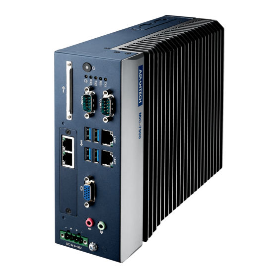
- Page 1 User Manual MIC-7900 Embedded Fan-less IPC System CoastIPC .com 866-412-6278...
- Page 2 English user manual included as a PDF file on the CD. Please disregard the Chinese hard copy user manual if the product is not to be sold and/or installed in China. MIC-7900 User Manual...
- Page 3 The documentation and the software included with this product are copyrighted 2017 by Advantech Co., Ltd. All rights are reserved. Advantech Co., Ltd. reserves the right to make improvements in the products described in this manual at any time without notice.
- Page 4 Because of Advantech’s high quality-control standards and rigorous testing, most of our customers never need to use our repair service. If an Advantech product is defec- tive, it will be repaired or replaced at no charge during the warranty period. For out- of-warranty repairs, you will be billed according to the cost of replacement materials, service time and freight.
- Page 5 Technical Support and Assistance Visit the Advantech web site at www.advantech.com/support where you can find the latest information about the product. Contact your distributor, sales representative, or Advantech's customer service center for technical support if you need additional assistance. Please have the following information ready before you call: –...
- Page 6 RESTRICTED ACCESS AREA: The equipment should only be installed in a Restricted Access Area. DISCLAIMER: This set of instructions is given according to IEC 704-1. Advantech disclaims all responsibility for the accuracy of any statements contained herein. MIC-7900 User Manual...
- Page 7 Packing List Before installation, please ensure the following items have been shipped: MIC-7900 bare-bone system x 1 MIC-7900 Startup manual x 1 P/N: 2001790000 MIC-7900 Startup manual x1 (CHT) P/N: 2001790010 MIC-7900 Driver CD x 1 P/N: 2061790000 ...
- Page 8 Power cord BSI 3PIN UK 1.8M AIIS-DIO32-00A1E AIIS-32bit GPIO module 98R2C48510E Isolation COM module Supports i-Door module (MOS series), except PoE Please refer to Advantech website below or search "iDoor Module i-Door Module Mini PCIe Expansion Kit". (MOS series module) http://www.advantech.com.tw/products/idoor-module-mini-pcie- expansion-kit/sub_bc858a7f-a52b-441b-a59c-f511289f98bc...
-
Page 9: Table Of Contents
Ethernet ..................2 Chipset ...................... 3 1.3.1 Functional specification..............3 Mechanical Specifications................. 4 1.4.1 Dimensions ................... 4 Figure 1.1 MIC-7900 Mechanical Dimension Drawing ....4 1.4.2 Weight................... 5 Power Requirements................. 5 1.5.1 System power ................5 1.5.2 RTC battery................... 5 Environment Specification................. - Page 10 2.4.6 MIC-7900 MB I/O Connector ............17 Chapter AMI BIOS Setup......... 19 Introduction ..................... 20 Entering Setup ..................21 3.2.1 Main Setup.................. 21 3.2.2 Advanced BIOS Features Setup..........22 3.2.3 IntelRCSetup ................39 3.2.4 Security..................63 3.2.5 Boot .................... 64 3.2.6...
-
Page 11: Chapter 1 General Introduction
Chapter General Introduction This chapter gives background information on MIC-7900. -
Page 12: Introduction
& flexible expansion slot module (i-module). MIC-7900 supports Intel Xeon D-1559 & D-1539 processor and SO-DIMM DDR4 ECC or non- ECC memory up to 32 GB. MIC-7900 also supports full range of i-module that includ- ing MIC-75M13/MIC-75M40/MIC-75M20-01/MIC-75M11 and MIC-75S20. This sys- tem total supports a lot off storage space, five for 2.5’... -
Page 13: Chipset
Supports high-speed, full-speed, and low-speed capable Supports legacy keyboard/mouse software CPU: Intel Xeon Processor Broadwell-DE Power Supports ACPI 5.0 Management ACPI Power Management Logic Supported Power Connector: Plug-in block 4Px1 BIOS AMI 128Mb Flash BIOS via SPI MIC-7900 User Manual... -
Page 14: Mechanical Specifications
(note: LAN 3/4 is expanded by LAN module) TI PCM2912 16-bit DAC and 16-bit ADC Audio Audio Jack (MIC-in & Line-out) mono recording, DAC support 16bit Battery backup BR2032 3V/190mAh Mechanical Specifications 1.4.1 Dimensions UNIT : mm MIC-7900 User Manual... -
Page 15: Weight
Figure 1.1 MIC-7900 Mechanical Dimension Drawing 1.4.2 Weight 2.9kg (6.39lbs) Power Requirements 1.5.1 System power Minimum power input: DC12V (-25%) -30V (+20%), Absolute Maximum Ratings Voltage is 9V - 36V 1.5.2 RTC battery BR2032 3 V/190 mAh Environment Specification 1.6.1... - Page 16 MIC-7900 User Manual...
-
Page 17: Chapter 2 H/W Installation
Chapter H/W Installation This chapter introduces external I/O and the installation of MIC-7900 hardware. -
Page 18: Introduction
2.2.1 Jumper Description You may configure the MIC-7900 to match the needs of your application by setting jumpers. A jumper is a metal bridge used to close an electric circuit. It consists of two metal pins and a small metal clip (often protected by a plastic cover) that slides over the pins to connect them. -
Page 19: Jumper List
Clear CMOS 2.2.2.2 System AT/ATX Mode Function Option MIC-7900 support AT or ATX mode and Default is ATX module. if you want to change to AT mode that you can find AT/ATX mode jumper in motherboard. PSON1 System AT/ATX mode option... -
Page 20: Connectors
MIC-7900 provides two 9 pin D-Sub connector that offer RS-232/422/485. Default setting is RS-232 and can be modified by BIOS selection table. MIC-7900 also pro- vides 4 more COM RS-232 Pin header inside which expanded by cable. You can find cable in accessory box. -
Page 21: Figure 2.2 Ethernet Connector
2.3.1.2 Ethernet Connector (LAN) MIC-7900 is equipped with four Ethernet controllers that are fully compliant with IEEE 802.3u 10/100/1000 Mbps CSMA/CD standards. These four LAN are equipped with intel i210IT.. The Ethernet port provides a standard RJ45 jack connector with LED indicators on the front side to show its Active/Link status and Speed status. -
Page 22: Figure 2.4 Usb 3.0 Connector
2.3.1.4 USB 3.0 Connector MIC-7900 provides 4 USB 3.0 interface connectors, which give complete Plug & Play and hot swapping for up to 127 external devices. The USB interface complies with USB XHCI, Rev. 3.0. Please refer to the table below for pin assignments. -
Page 23: Figure 2.6 4-Pin Header
2.3.1.7 Power ON/OFF Button MIC-7900 comes with a Power On/Off button with LED indicators on the front side to show its On status (Green LED) and Off/Suspend status (RED LED), that supports dual function of Soft Power-On/Off (instant off or delay 4 seconds), and suspend. -
Page 24: Installation
2.4.1 HDD Installation Undo 4 screws and remove the bottom cover Undo 4 screws to remove HDD tray. Secure the HDD with 4xHDD screws (P/N:1930002235) Assemble SATA cable/power cable and replace HDD tray; secure with 4 screws. MIC-7900 User Manual... -
Page 25: Memory Installation
Please refer to i-module Manual for i-module assembly. 2.4.2 Memory Installation MIC-7900 supports DDR4 SO-DIMM ECC or Un-ECC type memory module. If you needs detail memory support list, please connect your distributor or sales represent- ative to order compatible memory modules. -
Page 26: Mini-Pcie Installation
COM 3/4 Ports Installation MIC-7900 has four standard serial ports. Two support RS-232/422/485. If more serial ports are needed, MIC-7900 can expand up to six serial ports by cable (RS-232 only). There is one DP9 cable in the accessory box. -
Page 27: Mic-7900 Mb I/O Connector
COM 3/4 Replace LAN module for COM 5/6 2.4.6 MIC-7900 MB I/O Connector Internal USB 2.0 DDR4 Socket M.2 (PCIE signal) U-SIM SATA Con. (SATA 1 ~4) USB 2.0 Con. PSON1 Remote Power Con. SATA Power Con. Mini-PCIe socket (Power 1 ~4) COM 5/6 LAN module Con. - Page 28 MIC-7900 User Manual...
-
Page 29: Ami Bios Setup
Chapter AMI BIOS Setup This chapter introduces how to set BIOS configuration data. -
Page 30: Introduction
With the AMI BIOS Setup program, you can modify BIOS settings and control the special features of your computer. The Setup program uses a number of menus for making changes and turning special features on or off. This chapter describes the basic navigation of the MIC-7900 setup screens. MIC-7900 User Manual... -
Page 31: Entering Setup
Date using the <Arrow> keys. Enter new values through the keyboard. Press the <Tab> key or the <Arrow> keys to move between fields. The date must be entered in MM/DD/YY format. The time must be entered in HH:MM:SS format. MIC-7900 User Manual... -
Page 32: Advanced Bios Features Setup
3.2.2 Advanced BIOS Features Setup Select the Advanced tab from the MIC-7900 setup screen to enter the Advanced BIOS Setup screen. You can select any of the items in the left frame of the screen, such as ACPI Settings and hit <enter> to go to the sub menu for that item. You can display an Advanced BIOS Setup option by highlighting it using the <Arrow>... - Page 33 3.2.2.1 Trusted Computing Security Device Support This item allows users to enable or disable “Security Device Support”. 3.2.2.2 ACPI Settings Enable ACPI Auto Configuration This item allows users to select Enabled or Disabled. MIC-7900 User Manual...
- Page 34 This item allows users to select Enabled or Disabled. 3.2.2.3 NCT 6106D Super IO Configuration MIC-7900 supports 2xRS-232/422/485 & 2-RS-232 in front side. There are 2 more RS-232s (Serial Ports 5 & 6) signal at M/B, you can find a cable in the accessory box. MIC-7900 User Manual...
- Page 35 – Change Settings This item allows users to Change Settings of Serial Ports. The default option is "Auto". – Device Mode This item allows users to select the mode of serial port. The default option is "RS-232". MIC-7900 User Manual...
- Page 36 Serial Port 6 Configuration – Serial Port This item allows users to select Disabled or Enabled "Serial Port". – Change Settings This item allows users to change settings of serial ports. The default option is "Auto". MIC-7900 User Manual...
- Page 37 Case Open Warning This item allows users to select Enabled or Disabled for "Case Open Warning”. Note! MIC-7900 system does not support case-open switch in chassis. If your application needs case open function, please connect your distributor or sales representative.
- Page 38 i-Module FAN This item allows users to select Manual Mode or SmartFan Mode for i-Module. Note! MIC-7900 system does not support FAN. This function only workable in MIC-7900 with i-Module +FAN. PC Health Status MIC-7900 system has design-in temperature sensor to monitor system tempera- ture.
- Page 39 3.2.2.5 S5 RTC Wake Settings Wake System from S5 This item allows user to select Disabled or Fixed Time for "Wake System from S5" MIC-7900 User Manual...
- Page 40 Wake system for SW [Fixed Time] Select 0-23 For example enter 3 for 3am and 15 for 3pm. – Wake up hour – Wake up minute – Wake up second MIC-7900 User Manual...
- Page 41 3.2.2.6 Serial Port Console Redirection Console Redirection This item allows user to select Enabled or Disabled for "Console Redirection" MIC-7900 User Manual...
- Page 42 This item allows user to select Enabled or Disabled for "VT-UTF8 Combo Key Support" – Recorder Mode This item allows user to select Enabled or Disabled for "Recorder Mode" – Resolution 100x31 This item allows user to select Enabled or Disabled for "Resolution 100x31" MIC-7900 User Manual...
- Page 43 This item allows user to select Enabled or Disabled for "Console Redirection" Console Redirection Settings The setting specify how the host computer and the remote computer (which the user is using) will exchange data. Both computers should have the same or compatible settings. MIC-7900 User Manual...
- Page 44 This item allows user to select for "Bits per second". The default option is "115200". – Flow Control This item allows user to select None or Hardware RTS/CTS or Software Xon/ Xoff for "Flow Control". The default option is "None". MIC-7900 User Manual...
- Page 45 This item allows user to select for "PCI-X Latency Timer". The default option is "64 PCI Bus Clocks". Above 4G Decoding This item allows user to select Enabled or Disabled for "Above 4G Decoding" SR-IOV Support This item allows user to select Enabled or Disabled for "SR-IOV Support" MIC-7900 User Manual...
- Page 46 This item allows user to select for "Link training Retry". The default option is "5". Link Training Timeout (uS) Defines number of Microseconds software will wait before polling 'Link Training' bit in Link Status register. Value range from 10 to 10000 uS. MIC-7900 User Manual...
- Page 47 This item allows user to select Do not launch or UEFI or Legacy for "Video". The default option is "Legacy". Other PCI devices This item allows user to select Do not launch or UEFI or Legacy for "Other PCI devices". The default option is "Legacy". MIC-7900 User Manual...
- Page 48 Device reset time-out This item allows user to select for "Device reset time-out ". The default option is "20 sec". – Device power-up delay This item allows user to select Auto or Manual for "Device power-up delay" MIC-7900 User Manual...
-
Page 49: Intelrcsetup
3.2.3 IntelRCSetup 3.2.3.1 Processor Configuration MIC-7900 User Manual... - Page 50 Per-Socket Configuration CPU Socket 0 Configuration Cores Enabled Number of Cores to Enable. O means all cores. 12 cores available. IOT Cfg Cbo Bitmap (Hex) MIC-7900 User Manual...
- Page 51 Enable SMX This item allows user to select Enable or Disable for "SMX" Advanced Power Management Configuration EIST (P-states) When enabled, OS sets CPU frequency according load. When disabled, CPU frequency is set at max non-turbo. MIC-7900 User Manual...
- Page 52 Config TDP This item allows user to select Enable or Disable for "Config TDP" – Config TDP Level This item allows user to select Level for "Config TDP Level". The default option is "Nominal". MIC-7900 User Manual...
- Page 53 CPU P State Control – P State Domain This item allows user to select ALL or ONE for "P State Domain" – P-state coordination MIC-7900 User Manual...
- Page 54 This item allows user to select Max Performance or Max Efficient for "Boot performance mode" – Turbo Mode This item allows user to select Enable or Disable for "Turbo Mode" – XE Ratio Limit Overclocking Lock This item allows user to select Enable or Disable for "Overclocking Lock" MIC-7900 User Manual...
- Page 55 Enhanced Halt State (C1E) This item allows user to select Enable or Disable for "Enhanced Halt State (C1E)" – OS ACPI Cx This item allows user to select ACPI C2 or ACPI C3 for "OS ACPI Cx" MIC-7900 User Manual...
- Page 56 CPU T State Control – ACPI T-States This item allows user to select Enable or Disable for "ACPI T-States" – T-State Throttle This item allows user to select for "T-State Throttle". The default option is "default". MIC-7900 User Manual...
- Page 57 CPU Thermal Management – Thermal Monitor This item allows user to select Enabled or Disabled for "Thermal Monitor". – PROCHOT RESPONSE This item allows user to select Pn clamping or Pm clamping for "PROCHOT RESPONSE". MIC-7900 User Manual...
- Page 58 Memory Frequency This item allows user to select for "Memory Frequency". The default option is "Auto". ECC Support This item allows user to select Auto or Disable or Enable for "ECC Support". The default option is "Auto". MIC-7900 User Manual...
- Page 59 Memory topology 3.2.3.3 IIO Configuration IIO PCIe Link on phase This item allows user to select for "IIO PCIe Link on phase". MIC-7900 User Manual...
- Page 60 IIO0 Configuration IOU1 (IIO PCIe Port 3) This item allows user to select for "IIOU1 (IIO PCIe Port 3)". – Socket 0 PcieD01F0 - Port 1A MIC-7900 User Manual...
- Page 61 This item allows user to select for "Link Speed". The default option is "Auto". – Socket 0 PcieD01F0 - Port 1B Link Speed This item allows user to select for "Link Speed". The default option is "Auto". MIC-7900 User Manual...
- Page 62 Gen3 Eq Mode This item allows user to select for "Gen3 Eq Mode". The default option is "Auto". Gen3 Spec Mode This item allows user to select for "Gen3 Spec Mode". The default option is "Auto". Gen3 Phase2 Mode MIC-7900 User Manual...
- Page 63 Override Max Lin Width This item allows user to select for "Override Max Lin Width". The default option is "Auto". PCI-E Port DeEmphasis This item allows user to select -6.0 dB or -3.5 dB for "Override Max Lin DeEm- phasisWidth".pport MIC-7900 User Manual...
- Page 64 This item allows user to select for "Gen3 UP TX Preset". The default option is "Auto". Hide Port This item allows user to select yes or no for "Hide Port?". Pcie Ecrc This item allows user to select Auto or Disable or Enable for "Pcie Ecrc". MIC-7900 User Manual...
- Page 65 Gen3 Eq Mode This item allows user to select for "Gen3 Eq Mode". The default option is "Auto". Gen3 Spec Mode This item allows user to select for "Gen3 Spec Mode". The default option is "Auto". Gen3 Phase2 Mode MIC-7900 User Manual...
- Page 66 12 or > 29 (39 for BIOS supporting > 4G PCI) disables BAR. Crosslink control Override This item allows user to select Auto or DSD/USP or USD/DSP for "Crosslink control Override". Hide Port This item allows user to select yes or no for "Hide Port?". MIC-7900 User Manual...
- Page 67 This item allows user to select Enable or Disable for "VTd Azalea VCp Opti- mizations". Intel VT for Directed I/O (VT-d) This item allows user to select Enable or Disable for "Intel VT for Directed I/O (VT-d)". MIC-7900 User Manual...
- Page 68 3.2.3.4 PCH Configuration PCH Devices PCH stated after G3 This item allows user to select S0 or S5 or Last State for "PCH stated after G3". LAN1 Controller MIC-7900 User Manual...
- Page 69 This item allows user to select Enabled or Disabled for "LAN2 Controller". Lan2 Option-ROM This item allows user to select Enabled or Disabled for "Lan2 Option-ROM". PICE Wake This item allows user to select Enabled or Disabled for "PICE Wake". PCH SATA Configuration MIC-7900 User Manual...
- Page 70 This item allows user to select Hard Disk Drive or Solid State Drive for "SATA Device Type". SATA Port 2 – Port 2 This item allows user to select Enabled or Disabled for "SATA Port 2". MIC-7900 User Manual...
- Page 71 Spin Up Device This item allows user to select Enabled or Disabled for "Spin Up Device". – SATA Device Type This item allows user to select Hard Disk Drive or Solid State Drive for "SATA Device Type". MIC-7900 User Manual...
- Page 72 USB Configuration USB Precondition This item allows user to select Enabled or Disabled for "USB Precondition". xHCI Mode This item allows user to select for "xHCI Mode". The default option is "Auto". 3.2.3.5 Server ME Configuration MIC-7900 User Manual...
-
Page 73: Security
3.2.4 Security Administrator Password This item allows user to set Administrator Password. User Password This item allows user to set User Password. MIC-7900 User Manual... -
Page 74: Boot
This item allows user to set "Boot Option #2". The default option is "Disabled". Boot Option #3 This item allows user to set "Boot Option #3". The default option is "Disabled". Network Device BBS Priorities MIC-7900 User Manual... - Page 75 This item allows user to set "Boot Option #1". Boot Option #2 This item allows user to set "Boot Option #2". Hard Drive BBS Priorities Boot Option #1 This item allows user to set "Boot Option #1". MIC-7900 User Manual...
-
Page 76: Save & Exit
This item allows users to select for Save as User Defaults. Restore User Defaults This item allows users to select for Restore User Defaults. Boot Override: This item allows users to set Override and it is based on user's configuration. MIC-7900 User Manual... -
Page 77: Software Installation
Chapter Software Installation This chapter introduces driver installation. -
Page 78: Chipset Software Installation Utility
4.1.1 Before you begin To facilitate the installation of the enhanced display drivers and utility software, read the instructions in this chapter carefully. The drivers for the MIC-7900 are located on the software installation CD. Note! The files on the software installation CD are compressed. Do not attempt to install the drivers by copying the files manually. -
Page 79: Windows Server 2012 / Windows 10 / Windows 8.1 / Windows 7
Navigate to the "02 Graphic" folder and click the executable file to complete the installation of the drivers for Windows Server 2012 / Windows 10 / Windows 8.1 / Windows 7 / Linux. Note! If you system wants to install Win 10, please select "Graphic_Win10_x64 file. MIC-7900 User Manual... -
Page 80: Install Usb 3.0
4.3.1 Introduction MIC-7900 provides 4x USB 3.0 and the data transfer rate of USB3.0 (5Gb/s) is 10 times to USB2.0 (480 Mbps). These 4 USB 3.0 port supports 5v standby power. Insert the driver CD into your system’s CD-ROM drive. Navigate to the "03 USB3.0"... -
Page 81: Windows Server 2012 / Windows 10 / Windows 8.1 / Windows 7
"Rel_20.7_PV_OEM Gene_205241". 4.5.1 Introduction MIC-7900 supports TPM 2.0. TPM IC is INFINEON SLB9665XQ2.0. Trusted Platform Module (TPM) technology is designed to provide hardware-based, security-related functions. It has a security-related crypto-processor that is designed to carry out cryptographic operations in a variety of devices and form factors. It includes multiple physical security mechanisms to help prevent malicious software from tampering with the security functions of the TPM. - Page 82 MIC-7900 User Manual...
-
Page 83: Appendix A Programming The Watchdog Timer
Appendix Programming the Watchdog Timer... -
Page 84: Programming The Watchdog Timer
Programming the Watchdog Timer The MIC-7900's watchdog timer can be used to monitor system software operation and take corrective action if the software fails to function within the programmed period. This section describes the operation of the watchdog timer and how to pro- gram it. - Page 85 Unlock NCT6106D Select register of watchdog timer Enable the function of the watchdog timer Use the function of the watchdog timer Lock NCT6106D MIC-7900 User Manual...
-
Page 86: Table A.1: Watchdog Timer Registers
Bit 5: Write 1 to generate a timeout signal immedi- ately and automatically return to 0. [default=0] Bit 4: Read status of watchdog timer, 1 means timer is “timeout”. AA (hex) ----- Write this address to I/O port 2E (hex) to lock the watchdog timer 2. MIC-7900 User Manual... -
Page 87: Example Program
Inc dx Mov al,10 Out dx,al ;----------------------------------------------------------- Dec dx ; Lock NCT6106D Mov al,0aah Out dx,al Enable watchdog timer and set 5 minutes as timeout interval ;----------------------------------------------------------- Mov dx,2eh ; Unlock NCT6106D Mov al,87h Out dx,al Out dx,al MIC-7900 User Manual... - Page 88 Enable watchdog timer to be reset by mouse ;----------------------------------------------------------- Mov dx,2eh ; Unlock NCT6106D Mov al,87h Out dx,al Out dx,al ;----------------------------------------------------------- Mov al,07h ; Select registers of watchdog timer Out dx,al Inc dx Mov al,08h Out dx,al ;----------------------------------------------------------- MIC-7900 User Manual...
- Page 89 Dec dx ; Enable the function of watchdog timer Mov al,30h Out dx,al Inc dx Mov al,01h Out dx,al ;----------------------------------------------------------- Dec dx ; Enable watchdog timer to be strobed reset by keyboard Mov al,0f2h Out dx,al Inc dx In al,dx Or al,40h Out dx,al MIC-7900 User Manual...
- Page 90 Dec dx ; Generate a time-out signal Mov al,0f2h Out dx,al ;Write 1 to bit 5 of F7 register Inc dx In al,dx Or al,20h Out dx,al ;----------------------------------------------------------- Dec dx ; Lock NCT6106D Mov al,0aah Out dx,al MIC-7900 User Manual...
-
Page 91: Appendix B Programming The Gpio
Appendix Programming the GPIO... -
Page 92: Supported Gpio Register
Extended Function Index Registers (EFIRs) The EFIRs are write-only registers with port address 2Eh or 4Eh on PC/AT systems. Extended Function Data Registers (EFDRs) The EFDRs are read/write registers with port address 2Fh or 4Fh on PC/AT systems MIC-7900 User Manual... -
Page 93: Gpio Example Program
MOV AL, F1H OUT DX, AL MOV DX, 2FH MOV AL, ??H ; Put the output value into AL OUT DX, AL ------------------------------------------------------------ Exit extended function mode | ------------------------------------------------------------ MOV DX, 2EH MOV AL, AAH OUT DX, AL MIC-7900 User Manual... - Page 94 No part of this publication may be reproduced in any form or by any means, electronic, photocopying, recording or otherwise, without prior written permis- sion of the publisher. All brand and product names are trademarks or registered trademarks of their respective companies. © Advantech Co., Ltd. 2017...
Need help?
Do you have a question about the MIC-7900 and is the answer not in the manual?
Questions and answers