Advantech MIC-770 User Manual
Embedded ipc
Hide thumbs
Also See for MIC-770:
- Startup manual (5 pages) ,
- User manual (92 pages) ,
- Startup manual (16 pages)
Table of Contents
Advertisement
Advertisement
Table of Contents

Related Manuals for Advantech MIC-770


Summary of Contents for Advantech MIC-770
- Page 1 User Manual MIC-770 Embedded IPC...
- Page 2 The documentation and the software included with this product are copyrighted 2019 by Advantech Co., Ltd. All rights are reserved. Advantech Co., Ltd. reserves the right to make improvements in the products described in this manual at any time without notice.
- Page 3 Because of Advantech’s high quality-control standards and rigorous testing, most of our customers never need to use our repair service. If an Advantech product is defec- tive, it will be repaired or replaced at no charge during the warranty period. For out- of-warranty repairs, you will be billed according to the cost of replacement materials, service time and freight.
- Page 4 Technical Support and Assistance Visit the Advantech web site at www.advantech.com/support where you can find the latest information about the product. Contact your distributor, sales representative, or Advantech's customer service center for technical support if you need additional assistance. Please have the following information ready before you call: –...
- Page 5 RESTRICTED ACCESS AREA: The equipment should only be installed in a Restricted Access Area. DISCLAIMER: This set of instructions is given according to IEC 704-1. Advantech disclaims all responsibility for the accuracy of any statements contained herein. MIC-770 User Manual...
- Page 6 Packing List Before installation, please ensure the following items have been shipped: MIC-770 bare-bone system x1 MIC-770 Startup manual x1 P/N: 2041077000 4-pin Phoenix connector P/N: 1652003234 Mounting bracket x2 P/N: 1960070543T001 SATA cable x1...
- Page 7 HDMI accessory kit 98R1750040E Remote switch accessory kit 98R1790040E Dual LAN module (MIC-770Q-00A1 only) Supports i-Door module (MOS series), except PoE Please refer to Advantech website below or search "iDoor Module i-Door Module Mini PCIe Expansion Kit". (MOS series module) http://www.advantech.com.tw/products/idoor-module-mini-pcie- expansion-kit/sub_bc858a7f-a52b-441b-a59c-f511289f98bc...
- Page 8 MIC-770 User Manual viii...
-
Page 9: Table Of Contents
Ethernet ..................3 Chipset ...................... 3 1.3.1 Functional specification..............3 Mechanical Specifications................. 4 1.4.1 Dimensions ................... 4 Figure 1.1 MIC-770 Mechanical Dimension Drawing ....4 1.4.2 Weight................... 4 Power Requirements................. 5 1.5.1 System power ................5 1.5.2 RTC battery................... 5 Environment Specification................. - Page 10 Internal USB 2.0 Installation (Q SKU only) ......... 18 2.4.5 COM 3/4/5/6 Ports Installation............ 18 2.4.6 Expansion module Installation (Optional) ........19 2.4.7 MIC-770 MB I/O connector ............21 Chapter BIOS Operation ......... 23 Introduction ..................... 24 Figure 3.1 Main setup screen ........... 24 Entering BIOS Setup................
- Page 11 Programming the Watchdog Timer ..........68 Table A.1: Watchdog Timer Registers ........70 A.1.3 Example Program ............... 71 Appendix B Programming the GPIO .....75 Supported GPIO Register ............... 76 B.1.1 GPIO Registers................76 B.1.2 GPIO Example Program ............. 77 MIC-770 User Manual...
- Page 12 MIC-770 User Manual...
-
Page 13: Chapter 1 General Introduction
Chapter General Introduction This chapter gives background information on MIC-770. -
Page 14: Introduction
DC power inputs. The rugged aluminum case not only provides a great thermal solution, but also resists high EMI/shock/vibration. MIC-770 is equipped with Intel® 8th Core i desktop CPU featuring 6 cores, making it highly suitable for embedded and industrial PC applications requiring high processor performance within limited spaces. -
Page 15: Ethernet
Supports high-speed, full-speed, and low-speed capable Supports legacy keyboard/mouse software Supports ACPI 5.0 Power ACPI Power Management Logic supported Management Power Connector: plug-in block 4Px1 BIOS AMI 256Mb Flash BIOS via SPI MIC-770 User Manual... -
Page 16: Mechanical Specifications
Supports to 16/20/24-bit DAC and 16/20/24-bit ADC resolution Supports: Line-out, Mic-in DAC supports 16/20/24-bit PCM format, multiple stereo recording Battery backup BR2032 3 V/190mAh Mechanical Specifications 1.4.1 Dimensions UNIT : mm Figure 1.1 MIC-770 Mechanical Dimension Drawing 1.4.2 Weight 2.8kg (6.17lbs) MIC-770 User Manual... -
Page 17: Power Requirements
5 ~ 500 Hz, 1 Oct/min., 1 hr/axis, x,y,z 3 axes. 1.6.6 Shock during operation When system is equipped with SSD only: 20 G, IEC 60068-2-27, half sine, 11 ms duration. 1.6.7 Safety UL/CB, CCC, BSMI 1.6.8 CE, FCC, CCC, BSMI MIC-770 User Manual... - Page 18 MIC-770 User Manual...
-
Page 19: Chapter 2 H/W Installation
Chapter H/W Installation This chapter introduces external IO and the installation of MIC-770 hardware. -
Page 20: Introduction
2.2.1 Jumper description You may configure the MIC-770 to match the needs of your application by setting jumpers. A jumper is a metal bridge used to close an electric circuit. It consists of two metal pins and a small metal clip (often protected by a plastic cover) that slides over the pins to connect them. -
Page 21: Jumper List
Clear CMOS 2.2.2.2 System AT/ATX mode function option MIC-770 supports AT or ATX mode and default is ATX module. If you want to change to AT mode you can find AT/ATX mode jumper on the motherboard. PSON1 System AT/ATX mode option... -
Page 22: Connectors
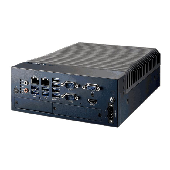
Connectors 2.3.1 MIC-770 External I/O Connectors COM1 TX/RX USB3.1/3.0 : Q370 COM2 USB2.0 : H310 TX/RX LAN2/LAN1 DATA COM1/2 Chassis GND Power Line out USB3.0 HDMI 9 - 36 VDC Mic in Figure 2.1 MIC-770 Front View MIC-770 User Manual... -
Page 23: Table 2.2: Com Connector Pin Assignments
2.3.1.2 Ethernet connector (LAN) MIC-770 is equipped with two Ethernet controllers that are fully compliant with IEEE 802.3u 10/100/1000 Mbps CSMA/CD standards. LAN1 is equipped with Intel i219 and LAN2 is equipped with Intel i210. The Ethernet port provides a standard RJ45 jack connector with LED indicators on the front side to show its Active/Link status and Speed status. -
Page 24: Figure 2.3 Audio Connector
2.3.1.3 Audio connector MIC-770 has two stereo audio ports with phone jack connectors, one Line_Out, one Mic_In. The audio chip is controlled by ACL892, and it’s compliant with AZALIA stan- dard. Figure 2.3 Audio Connector Table 2.4: Audio Connector Pin Assignments... -
Page 25: Figure 2.5 Vga Connector
2.3.1.5 VGA Connector The MIC-770 provides a high resolution VGA interface with a 15-pin D-sub connector to support a VGA CRT monitor. It supports display resolution of up to 2048 x 1152 @ 60 Hz. Figure 2.5 VGA Connector Table 2.6: VGA Connector Pin Assignments... -
Page 26: Figure 2.7 4-Pin Header
2.3.1.8 Power ON/OFF button MIC-770 comes with a Power On/Off button with LED indicators on the front side to show its On status (Green LED) and Off/Suspend status (RED LED), that supports dual function of Soft Power-On/Off (instant off or delay 4 seconds), and suspend. -
Page 27: Installation
Installation 2.4.1 HDD installation Undo 4 screws and remove the bottom cover Undo 4 screws to remove the HDD tray. MIC-770 User Manual... - Page 28 Secure the HDD with 4 x HDD screws (P/N:1930002235). Assemble SATA cable/power cable and replace HDD tray; secure with 4 screws. Replace bottom cover. Note! Please refer to i-module Manual for i-module assembly. MIC-770 User Manual...
-
Page 29: Memory Installation
H310: 1x mini PCIe (via USIM), 1x mSATA Undo 4 screws and remove the bottom cover. Install the module in Mini PCIe socket 1, or m-SATA in Mini PCIe socket 2 and secure with screws. Replace bottom cover and secure with screws. MIC-770 User Manual... -
Page 30: Internal Usb 2.0 Installation (Q Sku Only)
COM 3/4/5/6 Ports Installation MIC-770 has support two standard RS-232/422/485 serial ports. If more serial ports are needed, MIC-770 can expand up to four serial ports by cable (RS-232 only). There is one DB9 cable in the accessory box. Undo 4 screws and remove the bottom cover. -
Page 31: Expansion Module Installation (Optional)
2.4.6 Expansion module Installation (Optional) MIC-770 supports below optional modules for different applications. A: Expansion module: 32-bit GPIO module, P/N: AIIS-DIO32-00A1E Secondary DVI module, P/N: 98R1750000E HDMI/Remote power module, P/N: 98R1750010E HDMI module, P/N: 98R1750030E Remote power module: 98R1750040E Dual LAN module, P/N: 98R1790040E (MIC-770Q only) - Page 32 Assemble module on M/B (Note: Optional expansion modules need to connect with a cable. (Please refer to MB internal I/O connector specification at IO con- nector page for GPIO connector.) Assemble module baffle with screws. Replace bottom cover and secure with screws. MIC-770 User Manual...
-
Page 33: Mic-770 Mb I/O Connector
2.4.7 MIC-770 MB I/O connector Internal USB 2.0 DDR4 socket USIM GPIO MiniPCIe support mSATA SATA COM5/6 MiniPCIe support USIM COM3/4 eFuse(SW5) ATX/AT jumper Clear CMOS Remote switch HDMI/DVI Con MIC-770 User Manual... - Page 34 MIC-770 User Manual...
-
Page 35: Chapter 3 Bios Operation
Chapter BIOS Operation... -
Page 36: Figure 3.1 Main Setup Screen
The Setup Utility uses a number of menus for making changes and turning the specific features on or off. This chapter describes the basic navigation of the MIC-770 setup screens. Figure 3.1 Main setup screen AMI’s BIOS ROM has a built-in Setup program that allows users to modify the basic... -
Page 37: Entering Bios Setup
The right frame displays the key legend. The key legend above is an area reserved for a text message. When an option is selected in the left frame, it is highlighted in white. Often a text message will accom- pany it. MIC-770 User Manual... -
Page 38: Main Menu
System Date using the <Arrow> keys. Enter new values through the keyboard. Press the <Tab> key or the <Arrow> keys to move between fields. The date must be entered in MM/DD/YY format. The time must be entered in HH:MM:SS format. MIC-770 User Manual... -
Page 39: Advanced Bios Features Setup
3.2.2 Advanced BIOS Features Setup Select the Advanced tab from the MIC-770 setup screen to enter the Advanced BIOS setup screen. You can select any of the items in the left frame of the screen, such as CPU configuration, to go to the sub menu for that item. You can display an Advanced BIOS Setup option by highlighting it using the <Arrow>... -
Page 40: Figure 3.4 Platform Misc Configuration
Platform Misc Configuration – Native PCIE Enable PCI Express Native Support Enable/Disable. This is only available in Vista. – Native ASPM On enable, Vista will control the ASPM support for the device. If disabled, the BIOS will. MIC-770 User Manual... -
Page 41: Figure 3.5 Cpu Configuration
"Enable or Disable" utilization of additional hardware capabilities provided by Intel Trusted Execution Technology. Changes require a full power cycle to take effect. Rest AUX Content Reset TPM AUX content. TXT may not be functional after AUX content gets reset. MIC-770 User Manual... -
Page 42: Figure 3.6 Power & Performance
Figure 3.6 Power & Performance Figure 3.7 CPU Power Management Control Boot Performance Select the performance state that the BIOS will set before OS handoff. Intel(R) Speedstep(tm) Allows more than two frequency ranges to be supported. MIC-770 User Manual... -
Page 43: Figure 3.8 Pch-Fw Configuration
Turbo Mode Turbo mode. C states Intel C states setting for power saving. 3.2.2.4 PCH-FW Configuration Figure 3.8 PCH-FW Configuration PCH-FW Version PCH-FW page shows Intel ME FW information. MIC-770 User Manual... -
Page 44: Figure 3.9 Amt Configuration
AMT Configuration Figure 3.9 AMT Configuration CIRA Configuration Figure 3.10 CIRA Configuration – Activate Remote Assistance Process Triggers CIRA boot MIC-770 User Manual... -
Page 45: Figure 3.11Asf Configuration
ASF Configuration Figure 3.11 ASF Configuration – PET Progress Enable or Disable PET Progress to receive PET event or not – WatchDog “Enable or Disable” Watchdog Timer MIC-770 User Manual... -
Page 46: Figure 3.12Secure Erase Configuration
Figure 3.12 Secure Erase Configuration – Secure Erase mode Change Secure Erase module behavior to “Simulated or Real”. – Force Secure Erase “Enable or Disable” to force Secure Erase on next boot. OEM Flags Settings Figure 3.13 OEM Flags Settings MIC-770 User Manual... -
Page 47: Figure 3.14Mebx Resolution Settings
MEBx Resolution Settings Figure 3.14 MEBx Resolution Settings – Non-UI Mode Resolution Set resolution for non-UI text mode. – UI Mode Resolution Set resolution for UI text mode. – Graphics Mode Resolution Set resolution for graphics mode. MIC-770 User Manual... -
Page 48: Figure 3.15Tpm Settings
3.2.2.5 Trusted Computing Figure 3.15 TPM Settings TPM Support “Enable or Disable” TPM Support. You can purchase Advantech LPC TPM mod- ule to enable TPM function. P/N: PCA-TPM-00B1E. MIC-770 User Manual... -
Page 49: Figure 3.16 Acpi Settings
OS. ACPI Sleep State Auto or S1 only or S3 only ACPI Sleep State. Lock Legacy Resources Enable or Disable Lock Legacy Resources. S3 Video Repost Enable or Disable S3 Video Repost. MIC-770 User Manual... -
Page 50: Figure 3.17Smart Settings
3.2.2.7 SMART Settings Figure 3.17 SMART Settings SMART Self Test Enable or Disable SMART Self Test on all HDDs during POST. MIC-770 User Manual... -
Page 51: Figure 3.18Super Io Configuration
3.2.2.8 Super IO Configuration MIC-770 supports 2 x RS-232/422/485 on the front side. MIC-770 has 4 more RS- 232 (Serial Port 3, 4, 5, 6) via 2x DB9 cables in accessory box. Figure 3.18 Super IO Configuration Figure 3.19 Serial Port 1 Configuration... -
Page 52: Figure 3.20Serial Port 2 Configuration
Figure 3.20 Serial Port 2 Configuration Figure 3.21 Serial Port 3 Configuration MIC-770 User Manual... -
Page 53: Figure 3.22Serial Port 4 Configuration
Figure 3.22 Serial Port 4 Configuration Figure 3.23 Serial Port 5 Configuration MIC-770 User Manual... -
Page 54: Figure 3.24Serial Port 6 Configuration
RS-232. When serial port 2 (COM2) is set to RS-485 mode via jumper JSETCOM1, this item should be selected as "RS-485 (Half Duplex)" and fur- ther set Auto Direction (Flow) Control setting to "On (enable) or Off (disable)". Default for this Device Mode is "RS-232". MIC-770 User Manual... -
Page 55: Figure 3.25Pc Health Status
This item allows users to disable or enable the Serial Port. – Change Settings This item allows users to change settings of the serial ports. The default set- ting is Auto. 3.2.2.9 H/W Monitor Figure 3.25 PC Health Status MIC-770 User Manual... -
Page 56: Figure 3.26Fan Configuration
Use this item to set the ACPI shutdown temperature. When the system reaches the shutdown temperature, it will be automatically shut down by the ACPI OS to protect the system from overheating damage. Watchdog Timer To Enable or Disable Watchdog Timer. MIC-770 User Manual... -
Page 57: Figure 3.27S5 Rtc Wake Settings
3.2.2.10 S5 RTC Wake Settings Figure 3.27 S5 RTC Wake Settings Wake system with Fixed Time To Enable or Disable System wake on alarm event. The system will wake on the hr:min:sec as specified. MIC-770 User Manual... -
Page 58: Figure 3.28Serial Port Console Redirection
Console Redirection Enable or Disable Legacy Console Redirection – Legacy Console Redirection Settings Legacy Console Redirection Settings Serial Port for Out-of-Band Management/ Windows Emergency Manage- ment services (EMS) – Console Redirection Console Redirection Enable or Disable MIC-770 User Manual... -
Page 59: Figure 3.29 Intel Txt Information
Intel TXT Information Figure 3.29 Intel TXT Information 3.2.2.13 PCI Subsystem Settings Figure 3.30 PCI Subsystem Settings PCI Settings Common for all Devices – Hot-Plug Support "Enable or Disable" PCI hot-plug support for the entire system. MIC-770 User Manual... -
Page 60: Figure 3.31Csm Configuration
Controls the execution of UEFI and Legacy Storage OpROM. – Video Controls the execution of UEFI and Legacy Video OpROM. – Other PCI devices Determines OpROM execution policy for devices other than Network, Stor- age, or Video. MIC-770 User Manual... -
Page 61: Figure 3.32Usb Configuration
Maximum time the device will take before it properly reports itself to the Host Controller. Auto uses default value: for a Root port it is 100 ms, for a Hub port the delay is take from Hub descriptor. MIC-770 User Manual... -
Page 62: Figure 3.33Network Stack
3.2.2.16 USB Network Stack Configuration Figure 3.33 Network Stack Network Stack "Enable or Disable" UEFI Network Stack. 3.2.3 Chipset Figure 3.34 Chipset This page provides information of the chipset on MIC-770. MIC-770 User Manual... -
Page 63: Figure 3.35System Agent (Sa) Configuration
3.2.3.1 System Agent (SA) Configuration Figure 3.35 System Agent (SA) Configuration 3.2.3.2 Graphics Configuration MIC-770 User Manual... -
Page 64: Figure 3.36Graphics Configuration
Primary Display Select PEG0/PEG1/PEG2/PEG3 graphics device should be Primary PEG. External Gfx Card Primary Display Configuration Primary PEG Select Auto/PEG11/PEG12 Primary PCIE Select Auto/PCIE1~PCIE19 Internal Graphics Auto or Disable or Enable Internal Graphics. MIC-770 User Manual... -
Page 65: Figure 3.37Peg Port Configuration
3.2.3.3 PEG Port Configuration Figure 3.37 PEG Port Configuration Figure 3.38 PEG Port Feature Configuration Enable Root Port Enable or disable the root port Max Link speed MIC-770 User Manual... -
Page 66: Figure 3.39Memory Configuration
- Detect Non-Compliance Device Detects non-compliance PCI Express device in PEG. If enabled, it will take more time during POST phase. 3.2.3.4 Memory Configuration Figure 3.39 Memory Configuration Maximum Memory Frequency Maximum memory frequency selections in Mhz. MIC-770 User Manual... -
Page 67: Figure 3.40Pch-Io Configuration
Enable or Disable PCIE to wake the system from S5. PowerOn by Modem "Enable and Disable" PowerOn by Modem Restore AC Power Loss Power off or Power on or Last State to restore AC Power Loss MIC-770 User Manual... -
Page 68: Figure 3.41Pci Express Root Port Setting
3.2.3.6 PCI Express Configuration Figure 3.41 PCI Express Root Port Setting PCI Express Root Port 1 Enable or Disable PCI Express Root Port. PCIe Speed Select "Auto, Gen1, Gen2, Gen3" for PCIe Speed MIC-770 User Manual... -
Page 69: Figure 3.42Sata Configuration
3.2.3.7 SATA and RST Configuration Figure 3.42 SATA Configuration SATA Controller(s) Enable or Disable SATA Controller SATA Mode Selection This can be configured as RAID or AHCI. MIC-770 User Manual... -
Page 70: Figure 3.43Usb Configuration
To identify the SATA that is connected to a Solid State or Hard Disk Drive. 3.2.3.8 USB Configuration Figure 3.43 USB Configuration XHCI Compliance mode Option to "Enable or Disable" XHCI compliance mode. Default is to disable com- pliance mode. MIC-770 User Manual... -
Page 71: Figure 3.44Hd Audio Configuration
3.2.3.9 HD Audio Configuration Figure 3.44 HD Audio Configuration HD Audio Control detection of the HD-Audio device. Disable = HDA will be unconditionally disabled Enable=HDA will be unconditionally enabled MIC-770 User Manual... -
Page 72: Figure 3.45Security Configuration
"Enable or Disable" the PCH BIOS Lock Enable feature. Required to be enabled to ensure SMM protection of flash. Force unlock on all GPIO pads If Enabled, BIOS will force all GPIO pads to be in an unlocked state. MIC-770 User Manual... -
Page 73: Security
Security Figure 3.46 Security Select Security Setup from the MIC-770 Setup main BIOS setup menu. All Security Setup options, such as password protection is described in this section. To access the sub menu for the following items, select the item and press <Enter>. -
Page 74: Boot
“On or Off” power-on state for the NumLock. Quiet Boot Enable or Disable Quiet Boot option. Boot Option Priorities Sets the boot order. Hard Drive BBS Priorities Sets the order of the legacy devices on this group. MIC-770 User Manual... -
Page 75: Save & Exit
Select Exit Discarding Changes from the Exit menu and press <Enter>. The fol- lowing message appears: Quit without saving? [Yes] [No] Select Yes to discard changes and exit. Discard Changes Select Discard Changes from the Exit menu and press <Enter>. MIC-770 User Manual... - Page 76 MIC-770 User Manual...
-
Page 77: Chapter 4 Software Installation
Chapter Software Installation This chapter introduces driver installation. -
Page 78: Before You Begin
Before you begin To facilitate the installation of the enhanced display drivers and utility software, read the instructions in this chapter carefully. The drivers for the MIC-770 are located on the software installation CD. Note! For system stability, installing the drivers in the following sequence is highly recommended: ... -
Page 79: Appendix A Programming The Watchdog Timer
Appendix Programming the Watchdog Timer... -
Page 80: Programming The Watchdog Timer
Programming the Watchdog Timer The MIC-770's watchdog timer can be used to monitor system software operation and take corrective action if the software fails to function within the programmed period. This section describes the operation of the watchdog timer and how to pro- gram it. - Page 81 Unlock NCT6106D Select register of watchdog timer Enable the function of the watchdog timer Use the function of the watchdog timer Lock NCT6106D MIC-770 User Manual...
-
Page 82: Table A.1: Watchdog Timer Registers
Bit 5: Write 1 to generate a timeout signal immedi- ately and automatically return to 0. [default=0] Bit 4: Read status of watchdog timer, 1 means timer is “timeout”. AA (hex) ----- Write this address to I/O port 2E (hex) to lock the watchdog timer 2. MIC-770 User Manual... -
Page 83: Example Program
Inc dx Mov al,10 Out dx,al ;----------------------------------------------------------- Dec dx ; Lock NCT6106D Mov al,0aah Out dx,al Enable watchdog timer and set 5 minutes as timeout interval ;----------------------------------------------------------- Mov dx,2eh ; Unlock NCT6106D Mov al,87h Out dx,al Out dx,al MIC-770 User Manual... - Page 84 Enable watchdog timer to be reset by mouse ;----------------------------------------------------------- Mov dx,2eh ; Unlock NCT6106D Mov al,87h Out dx,al Out dx,al ;----------------------------------------------------------- Mov al,07h ; Select registers of watchdog timer Out dx,al Inc dx Mov al,08h Out dx,al ;----------------------------------------------------------- MIC-770 User Manual...
- Page 85 Dec dx ; Enable the function of watchdog timer Mov al,30h Out dx,al Inc dx Mov al,01h Out dx,al ;----------------------------------------------------------- Dec dx ; Enable watchdog timer to be strobed reset by keyboard Mov al,0f2h Out dx,al Inc dx In al,dx Or al,40h Out dx,al MIC-770 User Manual...
- Page 86 Dec dx ; Generate a time-out signal Mov al,0f2h Out dx,al ;Write 1 to bit 5 of F7 register Inc dx In al,dx Or al,20h Out dx,al ;----------------------------------------------------------- Dec dx ; Lock NCT6106D Mov al,0aah Out dx,al MIC-770 User Manual...
-
Page 87: Appendix B Programming The Gpio
Appendix Programming the GPIO... -
Page 88: Supported Gpio Register
Extended Function Index Registers (EFIRs) The EFIRs are write-only registers with port address 2Eh or 4Eh on PC/AT systems. Extended Function Data Registers (EFDRs) The EFDRs are read/write registers with port address 2Fh or 4Fh on PC/AT systems MIC-770 User Manual... -
Page 89: Gpio Example Program
MOV AL, ED OUT DX, AL MOV DX, 2FH MOV AL, ??H ; Put the output value into AL OUT DX, AL ------------------------------------------------------------ Exit extended function mode | ------------------------------------------------------------ MOV DX, 2EH MOV AL, AAH OUT DX, AL MIC-770 User Manual... - Page 90 No part of this publication may be reproduced in any form or by any means, electronic, photocopying, recording or otherwise, without prior written permis- sion of the publisher. All brand and product names are trademarks or registered trademarks of their respective companies. © Advantech Co., Ltd. 2019...
Need help?
Do you have a question about the MIC-770 and is the answer not in the manual?
Questions and answers