Table of Contents
Advertisement
Quick Links
Advertisement
Table of Contents

Related Manuals for Mitsubishi Electric APRICOT FT4200


Summary of Contents for Mitsubishi Electric APRICOT FT4200
- Page 1 FT4200 Owner’s Handbook NATIONAL ACCREDITATION OF CERTIFICATION BODIES...
- Page 3 Adaptec is a registered trademark of Adaptec Inc. Cirrus Logic is a trademark of Cirrus Logic Inc. ® Intel and Pentium Pro are registered trademarks of Intel Corporation. ® ® Microsoft, MS-DOS, Windows and Windows NT are registered trademarks of Microsoft Corporation in the US and other countries.
-
Page 4: Safety And Regulatory Notices
N o t i c e s SAFETY AND REGULATORY NOTICES Power Information in the Owner’s Handbook relating to connection to the AC power supply may not apply outside the United Kingdom. The computer uses a safety ground and must be earthed. The system unit AC power supply cable is its ‘disconnect device’. - Page 5 N o t i c e s Laser Any fitted CD-ROM drive contains a laser system which is harmful to the eyes, and is classified as a CLASS 1 LASER PRODUCT according to IEC825 Radiation Safety of Laser Products (Equipment Classification: Requirements &...
- Page 6 N o t i c e s Standards The applicable standards for the country of sale will be shown on the label fixed to the rear of the system. Safety This product complies with the following European safety standards: EN60950 and when applicable, will include the national deviations as required for the following countries: Germany...
- Page 7 N o t i c e s IMPORTANT Power Cable Connections - UK ONLY This equipment is supplied with an AC power lead that has a non-removable moulded plug. If the AC supply outlets to be used are not suitable for the lead supplied with this computer, a new complete and suitable power lead should be obtained.
-
Page 8: Table Of Contents
CONTENTS Section One Chapter / page This section explains the setting up of your system and using the Front Panel Controls. There is information about back panel functions and ports, security aspects and the EISA Configuration Utility. This section also gives you details about how to install additional processors, memory and expansion cards. - Page 9 C o n t e n t s Fans Hard Disk Drive Cooling Fan Assembly Motherboard Cooling Fan Assembly Fan sub-assembly Motherboard System Motherboard Motherboard Power Distribution Panel Power Booards and Speaker Hard Disk Drive Power Distribution Panel Removable Media Drive Bay Power Distribution Panel Loudspeaker UPS and Battery Pack Uninterruptible Power Supply Unit...
- Page 10 Startup and operating, Upgrading and expansion...
-
Page 11: Setup And Operation
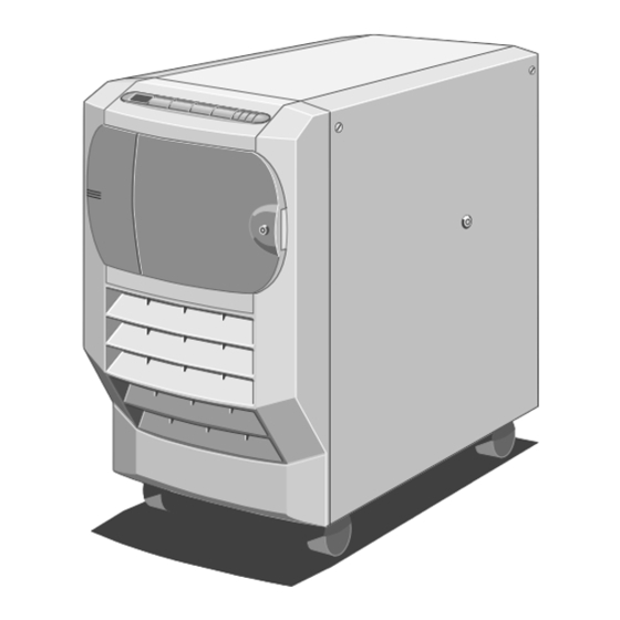
S e t u p a n d o p e r a t i o n SETUP AND OPERATION This section identifies the different parts of your system, explains what you should do when using the system for the first time and shows you how to carry out tasks which are part of normal operation. - Page 12 S e t u p a n d o p e r a t i o n The following paragraphs give a brief explanation each item on the front of the machine: ♦ Diagnostic Codes LCD - Displays diagnostic codes that indicate errors or normal stages in the boot process (see the chapter Diagnostic Codes).
-
Page 13: Rear Panel
S e t u p a n d o p e r a t i o n Rear Panel The rear panel contains the various ports and connectors as shown in the following illustration: Figure 1-2 Rear Panel Keyboard Connector (PS/2) Expansion Slot Openings Mouse Connector (PS/2) Stud for Antistatic Strap... -
Page 14: Machine Interior
S e t u p a n d o p e r a t i o n Machine Interior The interior of the server consists of the following main areas: ♦ Hard Disk Subsystem ♦ Removable Media Drive Bay ♦ Motherboard ♦... - Page 15 S e t u p a n d o p e r a t i o n Motherboard The motherboard contains the various disk controllers and other electronics necessary to control the server’s functions. It contains the memory and first two processors as well as PCI and EISA expansion slots.
-
Page 16: Setting Up Your System For The First Time
S e t u p a n d o p e r a t i o n Caution Caution You must maintain at least 15 cm space around the computer for adequate ventilation. Otherwise damage could result from overheating. Setting Up Your System for the First Time After you have unpacked the server and rolled it into position, use the jacking mechanism on the front castors to immobilise it. -
Page 17: Using The Front Panel
S e t u p a n d o p e r a t i o n Using the Front Panel This section describes the functions of the front panel during normal operation. Caution Caution Do not place any large or heavy objects on the top, especially near to the front facia. - Page 18 S e t u p a n d o p e r a t i o n Note Note It is good practice to warn anyone who may be accessing the system remotely, i.e. using the SMA from a remote computer via the modem port, before you press the button.
-
Page 19: Security
S e t u p a n d o p e r a t i o n ♦ - Pressing this button initialises the modem, which is ONTROL connected to the SMC modem port on the back panel of the server. If the modem initialisation is successful, the LCD displays the code 0000. -
Page 20: Automatic Failure Recovery
S e t u p a n d o p e r a t i o n Note Note When security is enabled and the door locked, you can use the KeyLOC infrared card to unblank the screen and enable the keyboard temporarily. The card will also silence a security alarm. - Page 21 S e t u p a n d o p e r a t i o n To run the ECU ♦ Locally, press F2 to run the Flash Disk Utility during the hardware boot sequence but before the operating system loads, remotely, run the Flash Disk Utility via the SMA.
-
Page 22: The Flash Memory
S e t u p a n d o p e r a t i o n ECU Help A help box is always available giving basic information on whichever menu item is currently highlighted. More detailed and useful information can be found as a simple tutorial in the first menu item, ‘Learn about configuring your computer’. - Page 23 S e t u p a n d o p e r a t i o n disk boot process fails. You can also copy files to the Flash Disk, e.g. hardware component configuration (.CFG) files which the ECU uses. If you are using the RAMdrive to enter details of an add-in card, you must remember to update the Flash disk before closing.
-
Page 24: Upgrading And Expansion
U p g r a d i n g a n d E x p a n s i o n UPGRADING AND EXPANSION This chapter explains the procedure for upgrading the CPU to one of higher speed and also provides information on upgrading the memory. You can also install expansion cards to increase your system’s capabilities. -
Page 25: Upgrading The Cpu
U p g r a d i n g a n d E x p a n s i o n Loosen the floating fasteners, located at the top left and right corners of the panel, until they move in and out freely. These fasteners are mounted in a spring fitting and should not be separated from the panel. - Page 26 U p g r a d i n g a n d E x p a n s i o n To gain access, it is required to remove the protective metal plate which covers the upper part of the electronics chamber. On completion of any work it is important to replace this panel for airflow integrity.
- Page 27 U p g r a d i n g a n d E x p a n s i o n Caution Caution All electronic computer components are sensitive to static electricity. Always take antistatic precautions before handling such components (see the Appendix for more details).
- Page 28 U p g r a d i n g a n d E x p a n s i o n and ZIF socket are designed to ensure that the processor can only install in the correct orientation. (The pin pattern is totally different at one end.) It will only fit into the socket one way.
-
Page 29: Additional Cpu Card
U p g r a d i n g a n d E x p a n s i o n Now adjust the processor multiplier and external bus clock speed switches on the motherboard (in conjunction with the new processor’s data sheet), as in the following tables. -
Page 30: Upgrading Memory
U p g r a d i n g a n d E x p a n s i o n The additional CPU board then fits into the same socket, with the processors facing downwards. Fit the metal support strut into place. Hooks at one end fit into the fan housing and the other end is fixed with a screw at the chamber rear. - Page 31 U p g r a d i n g a n d E x p a n s i o n The following table lists the supported memory configurations. Bank ONE socket 2 must be used first. Bank TWO, when used, must have an identical number of modules.
- Page 32 U p g r a d i n g a n d E x p a n s i o n Taking care to avoid touching any of the components on the DIMM, grip the top corners of the DIMM between thumb and first finger and carefully lift the module out of the socket.
-
Page 33: Installing And Removing Expansion Cards
U p g r a d i n g a n d E x p a n s i o n Installing and Removing Expansion Cards Important Note Important Note The procedures explained in this section are for authorised engineers only. The following illustration shows the positions of the expansion card slots in the electronics chamber: Figure 2-11 PCI and EISA/ISA Expansion Card Slots... - Page 34 U p g r a d i n g a n d E x p a n s i o n Position rules Additional SCSI controllers ♦ These must be fitted in one of the bottom three PCI slots to avoid boot-up conflicts with the onboard controllers.
- Page 35 U p g r a d i n g a n d E x p a n s i o n Removing Unplug all cables connected to the board and remove them completely. Remove the securing screw and pull the board out of the slot, leaving an empty space on the rear panel for the blanking plate again.
- Page 36 Detailed service Information for authorised engineers...
-
Page 37: Preliminary Service Information
P r e l i m i n a r y S e r v i c e I n f o r m a t i o n PRELIMINARY SERVICE INFORMATION If a problem should develop in your server within the warranty period, you should first contact the authorised maintainer for an engineer to service the unit. -
Page 38: Preliminary Service Tasks
P r e l i m i n a r y S e r v i c e I n f o r m a t i o n Preliminary Service Tasks Before you can perform a service procedure, you must do the following: Refer to the SMA and note down the value of the TimeOnCharge variable. -
Page 39: Hard Disk Drives And Modules
H a r d d i s k d r i v e s a n d m o d u l e s HARD DISK DRIVES AND MODULES Warning Warning Read completely the instructions detailed in chapter 3 at the beginning of the service section. - Page 40 H a r d d i s k d r i v e s a n d m o d u l e s Removing a drive Turn the hard disk tray release handle anti-clockwise until it stops, which is almost one complete turn. As you turn the handle, the tray ejects slightly.
-
Page 41: Hard Disk Drive Module
H a r d d i s k d r i v e s a n d m o d u l e s Fitting a replacement drive Warning Warning The drive and tray require very accurate assembly or damage can be caused to the connections. - Page 42 H a r d d i s k d r i v e s a n d m o d u l e s Figure 4-4 Unplugging the Ribbon Cable from a Module Hard Disk Module Data Connector Ribbon Cable Note Note One of the connectors, located underneath the cooling fan assembly, is less accessible...
-
Page 43: Hard Disk Drive Module Backplane
H a r d d i s k d r i v e s a n d m o d u l e s Hard Disk Drive Module Backplane The backplane on a hard disk drive module consists of seven small circuit boards which are fastened with screws to the metal framework and connected to each other by a flexible ribbon cable. - Page 44 H a r d d i s k d r i v e s a n d m o d u l e s Jumper Settings for the Removable Media SCSI Interface Board Each module backplane contains a removable media SCSI interface board, positioned at the top of the module.
- Page 45 H a r d d i s k d r i v e s a n d m o d u l e s The power circuit board lies in the centre of the backplane in each module as shown in the following diagram: Now use the four screws to fasten the module to the subsystem metalwork in the drive chamber.
- Page 46 H a r d d i s k d r i v e s a n d m o d u l e s In the electronics chamber, plug the appropriate ribbon cable onto the data connector on the backplane of the drive module: Figure 4-9 Plugging the Ribbon Cable to a Module Hard Disk Module Data Connector Ribbon Cable...
-
Page 47: Front Panels And Drives
F r o n t p a n e l s a n d d r i v e s FRONT PANELS AND DRIVES Warning Warning Read completely the instructions detailed in chapter 3 at the beginning of the service section. Front Bezel Removing Ensure that the removable media drive bay door is closed and locked. -
Page 48: Front Panel
F r o n t p a n e l s a n d d r i v e s Fitting Ensure that any hard disk drive module close to the front of the machine is removed. Plug the ribbon cable into the connector on the front panel. Fit the bezel onto the chassis and connect the eight screws, four on each side of the server, as shown in the following diagram: COMPA... - Page 49 F r o n t p a n e l s a n d d r i v e s Figure 5-3 Removing the circlip Circlip Top Hinge of Drive Bay Door Gently press down on the metal plate to detach it from the hinge as shown: Figure 5-4 Detaching the Hinge Metal Plate...
- Page 50 F r o n t p a n e l s a n d d r i v e s Now remove the two screws as shown: Figure 5-5 Removing Front Panel Supporting Metalwork Front Panel Supporting Securing Screws Metalwork Slide the supporting metalwork out of the bezel.
- Page 51 F r o n t p a n e l s a n d d r i v e s Fitting Attach the front panel to the supporting metalwork by means of the eight screws as shown: Figure 5-7 Front Panel Securing Screws Front Panel Metal Protrusion Holes Securing Screws...
-
Page 52: Removable Media Drives
F r o n t p a n e l s a n d d r i v e s Fit the circlip into the hinge as shown in the following illustration: Figure 5-9 Fitting Circlip Circlip Top Hinge of Drive Bay Door Removable Media Drives To gain access to the removable media drives and the System Management Controller (SMC) you must first remove the protective metal plate which... - Page 53 F r o n t p a n e l s a n d d r i v e s Removing Each drive is attached to a drive tray, which is in turn secured to the drive cage. To remove a tray from the cage: Unplug the data and power cables from the rear of the drive.
- Page 54 F r o n t p a n e l s a n d d r i v e s Lift the tray away from the drive. Fitting Your server is equipped with a tray and a blanking plate for each empty drive bay.
-
Page 55: System Management Controller (Smc)
S M C a n d f a n SYSTEM MANAGEMENT CONTROLLER BOARD AND FAN Warning Warning Read completely the instructions detailed in chapter 3 at the beginning of the service section. Although some of the board is hidden behind the cooling fan assembly, all of the fixing screws and cable connections are easily accessible. - Page 56 S M C a n d f a n Remove the two screw lock posts on the 25-way SMC serial port connector which is visible on the server’s back panel: Figure 6-2 SMC Serial Port Screw Lock Posts Screw Lock Posts Back panel Remove the seven fastening screws and lift the board out of the machine.
- Page 57 S M C a n d f a n System Controller Cooling Fan Assembly Removing Unplug the top fan connector on the SMC board (see fan connector graphic in “System Management Controller Board, Fitting”). Remove the two securing screws for the fan assembly, found on the back panel as shown: Figure 6-3 SMC Cooling Fan Securing Screws Securing Screws...
- Page 58 S M C a n d f a n Fitting Fit the assembly so that the two metal tabs at the bottom are inserted into corresponding slots. The assembly will then have a natural tilt towards the interior of the server. On each side of the assembly there is also a smaller tab which fits into a corresponding slot in the chassis.
-
Page 59: Hard Disk Drive Cooling Fan Assembly
C o o l i n g f a n s COOLING FANS Warning Warning Read completely the instructions detailed in chapter 3 at the beginning of the service section. Hard Disk Drive Cooling Fan Assembly You can remove and fit the hard disk drive cooling fan assembly without disturbing the adjacent disk drive module. - Page 60 C o o l i n g f a n s Remove two screws which fasten the fan assembly to the chassis: Figure 7-2 Removing the Hard Disk Cooling Fan Assembly Securing Screws Finger Grip Use the finger grip to slide the assembly towards you. Fitting Slide the assembly into position, remembering to feed the guide tabs into the positioning slots as shown in the following illustration:...
- Page 61 C o o l i n g f a n s At the same time, feed the fan cables through the cut-out in the corner of the metalwork above the assembly. These cables will need to be plugged into their respective sockets on the SMC board. Fasten the assembly to the chassis with the two screws.
-
Page 62: Motherboard Cooling Fan Assembly
C o o l i n g f a n s Motherboard Cooling Fan Assembly Removing Remove five screws on the side of the fan assembly. Remove any support struts fitted across the motherboard. Remove four more screws which fasten the assembly to the centre spine of the server, as shown: Figure 7-5 Removing Cooling Fan Assembly Side Securing Screws... - Page 63 C o o l i n g f a n s Fitting Fit the fan assembly into the interior of the server enough to connect the ribbon cable to the small power distribution board between the middle and bottom fans. Ensure the clips are latched onto the connector body.
-
Page 64: Motherboard
M o t h e r b o a r d MOTHERBOARD Warning Warning Read completely the instructions detailed in chapter 3 at the beginning of the service section. This chapter details the removal and refitting of the Motherboard, additional processor board and associated Power board. - Page 65 M o t h e r b o a r d Rotate the right edge of the plate slightly towards you and unhook the left edge. Removing the plate uncovers the motherboard: Figure 8-2 Motherboard in situ Support/retaining strut Busbars to Power supply Termination/extra CPU card SMIC card (bottom slot) Aux.
- Page 66 M o t h e r b o a r d Fig 8-3 Rear subplate screws Fixing screws system rear panel Now remove the System Management Interface Card (SMIC). Unplug its ribbon cable, which is attached to the distribution board at the top of the electronics chamber, using the ejector latches fitted to the sockets.
- Page 67 M o t h e r b o a r d 11. Unplug the two SCSI interface cables from the connectors at the bottom of the motherboard. 12. Using an M5 socket, release the five busbar connections at the base of the motherboard.
- Page 68 M o t h e r b o a r d Figure 8-6 Rear sub-plate assembly Top right corner of m’board Ports sub-plate Ports on motherboard Port mounting bolts Fitting the Motherboard Replace the six screws which secure the connector sub-plate, on the back panel, to the server chassis.
- Page 69 M o t h e r b o a r d Reconnect the hard disk cable from the drive module to the appropriate connector as it was originally. Caution Caution It is vital that you remember the exact cable and connector arrangement of your hard disks, particularly if you are using a RAID (Redundant Array of Independent Disks) configuration.
-
Page 70: Motherboard Power Distribution Panel
M o t h e r b o a r d Motherboard Power Distribution Panel The motherboard power distribution panel fixed to the inner roof of the electronics chamber and is positioned at right angles to the motherboard. The following illustration shows the connectors and the eight securing screws on the board: 7 8 9 10 Figure 8-9 Motherboard Power Distribution Panel... -
Page 71: Power Booards And Speaker
P o w e r b o a r d s a n d s p e a k e r POWER BOARDS AND SPEAKER There are two separate power distribution panels, one for hard disk drives and one for Removable Media drives. Warning Warning Read completely the instructions detailed in chapter 3 at the beginning of the... - Page 72 P o w e r b o a r d s a n d s p e a k e r Figure 9-2 Hard Disk Power Distribution Board Power Distribution Panel Removable Media Drives Securing Screws SMC Board HD Cooling Fan Assembly Fitting With all hard disk drives, drive modules and the motherboard cooling fan assembly removed, attach the hard disk distribution board to the...
-
Page 73: Removable Media Drive Bay Power Distribution Panel
P o w e r b o a r d s a n d s p e a k e r Removable Media Drive Bay Power Distribution Panel Removing In the electronics chamber, unplug two power cables as shown in the following diagram: Figure 9-3 Removable Drive Bay Power Distribution Panel Cable Connectors... -
Page 74: Loudspeaker
P o w e r b o a r d s a n d s p e a k e r Loudspeaker Removing Remove the motherboard cooling fan assembly as previosly detailed. Unplug the loudspeaker cable from the connector on the motherboard power distribution panel, as shown: Figure 9-4 Loudspeaker Connector Loudspeaker Connector... -
Page 75: Ups And Battery Pack
U P S a n d b a t t e r y p a c k UPS AND BATTERY PACK Warning Warning Read completely the instructions detailed in chapter 3 at the beginning of the service section. The UPS unit consists of the actual power supply and the accompanying battery pack. - Page 76 U P S a n d b a t t e r y p a c k Removing It is vitally important to ensure that the system is shut down, the battery pack circuit breaker switch is in the Off position and the system is disconnected from the mains electricity supply.
- Page 77 U P S a n d b a t t e r y p a c k Unplug three cables, one ribbon, one 12-way and one 16-way, from the power supply as shown: Figure 10-3 Disconnecting Power Supply Cables System Controller Removable Media Drive Bay Connector (Ribbon Cable) Connector (12-way)
- Page 78 U P S a n d b a t t e r y p a c k Loosen four floating fasteners, two on each side of the server, until they are free of the power supply unit, as indicated in the following diagram: Figure 10-4 Power Supply Floating Fasteners Floating Fasteners Front Bezel...
- Page 79 U P S a n d b a t t e r y p a c k Warning Warning This Power supply is heavy. It is strongly advised to have a second person with you to assist before you either fully remove the assembly from the server, or pick it up to fit it into its position in the server.
- Page 80 U P S a n d b a t t e r y p a c k Secure the unit to the chassis with the six screws as shown: Figure 10-7 Power Supply Securing Screws Now tighten the four floating fasteners, two on each side, located towards the front of the machine: Figure 10-8 Power Supply Floating Fasteners Floating Fasteners...
- Page 81 U P S a n d b a t t e r y p a c k Plug the ribbon, 12-way and 16-way cables into their connectors on the power supply. ◊ Note that these connectors are keyed and can only be fitted in one position.
-
Page 82: Ups Battery Pack
U P S a n d b a t t e r y p a c k Figure 10-10 Bus Bars Motherboard Bus Bars Bus Bars for Hard Disk Power Distribution Panel Caution Caution The hardware used to hold the busbar connections must be tightened using a torque wrench set to 5 Newton meters (Nm). - Page 83 U P S a n d b a t t e r y p a c k Important - Warning Important - Warning The battery pack contains lead acid batteries. In the EEC the directive 91/157/EEC (plus subsequent amendment 93/86/EEC) designates batteries containing lead to be handled as a dangerous substance.
- Page 84 U P S a n d b a t t e r y p a c k Fitting Make sure that the battery pack power connector is visible and accessible. Carefully lift the battery pack over the ‘end-stop’ and slide it far enough into the chassis to reconnect the battery pack power connector.
- Page 85 Technical information and Appendix...
-
Page 86: Technical Information Overview
T e c h n i c a l i n f o r m a t i o n TECHNICAL INFORMATION OVERVIEW This section contains technical information about your Apricot under the following topics: Topics covered Chapter Section layout Functional Architecture Memory Central Processing Unit... -
Page 87: Functional Architecture
T e c h n i c a l i n f o r m a t i o n Functional Architecture Your server’s functional divisions consist of the following: ♦ Motherboard ♦ System Management Controller ♦ Front Panel ♦ Uninterruptible Power Supply (UPS) ♦... - Page 88 T e c h n i c a l i n f o r m a t i o n Description The architecture of your server supports symmetrical multiprocessing (SMP) and a variety of operating systems. The server is equipped with both PCI (Peripheral Component Interconnect) and EISA (Extended Industry Standard Architecture) busses.
-
Page 89: Memory
T e c h n i c a l i n f o r m a t i o n Memory Server memory is located in two memory slot areas on the motherboard. Fully loaded, these provide 2 Gbytes of common high-speed memory for the server. - Page 90 T e c h n i c a l i n f o r m a t i o n The server supports both base (conventional) and extended memory. Base memory is located at addresses 00000h to 9FFFFh (the first 640 Kbytes). Extended memory begins at address 100000h (1 Mbyte) and extends to the limit of addressable memory (2 Gbytes).
-
Page 91: Central Processing Unit
T e c h n i c a l i n f o r m a t i o n Central Processing Unit The server’s first two CPUs are located on the motherboard. The motherboard has two type 8 ZIF sockets to become either a single or a dual processor board. -
Page 92: Motherboard
M o t h e r b o a r d MOTHERBOARD Motherboard layout Figure 12-1 Motherboard details Slot for CPU/termination card Busbar connections to PSU VRM8 socket for processor ‘B’ EISA expansion sockets DIMMs 1 to 4 (top to bottom) PCI expansion sockets ZIF socket for processor ‘B’... -
Page 93: Expansion Slots
M o t h e r b o a r d Expansion Slots EISA Slots The four EISA bus slots on the motherboard provide for expansion and performance enhancement. One of these shares a common chassis I/O expansion slot with one of the PCI slots. If you use this for an EISA slot, you cannot use it for PCI. - Page 94 M o t h e r b o a r d I/O Map (continued overleaf) I/O Address(es) Resource 0000 – 001F DMA controller 1 0020 – 0021 Interrupt controller 1 0022 – 0023 EISA bridge configuration space access ports 0024 – 0025 AIP configuration space access ports 0026 –...
- Page 95 M o t h e r b o a r d I/O Address(es) Resource 0462 Software NMI 0464 Last EISA Bus master granted 0480 – 048F DMA High Page Register. 04C0 – 04CF DMA Controller 2, High Base Register. 04D0 – 04D1 Interrupt Controllers 1 and 2 Control Register.
- Page 96 M o t h e r b o a r d Direct Memory Access Channels Channel Device (add-in board) (add-in board) Diskette drive Reserved Reserved (add-in board) (add-in board) (add-in board) ISA Interrupts Device Interrupt Parity error Interval timer Keyboard buffer full Reserved, cascade interrupt from slave PIC Onboard serial port B (COM2), if enabled Onboard serial port A (COM1), if enabled...
- Page 97 M o t h e r b o a r d Jumper and switch settings All of the following settings should not normally be changed. BIOS recovery (Identified at 16 on motherboard diagram) Pins Pins Action Recover Normal Clear BIOS settings (Identified at 18 on motherboard diagram) Pins Pins...
-
Page 98: Bus Connections And Ports
M o t h e r b o a r d Bus connections and ports On-Board SCSI Controllers The system board includes two Adaptec controller chips, channels A and B, interfacing directly to the second PCI bus. SCSI bus A Controlled by an on-board Adaptec AIC7850 having integrated single ended SCSI drivers for direct connection to an 8 bit fast (10Mhz) bus. - Page 99 M o t h e r b o a r d Parallel Port The parallel and video connectors share a common housing. When viewed on the rear panel, the parallel port is on the right. Signal Signal Strobe ACK (acknowledge) Data bit 0 Busy Data bit 1...
- Page 100 M o t h e r b o a r d VGA Video Port When viewed on the rear panel, the video port is on the left. Signal Signal GND (ground) Green 11-12 NC (not connected) Blue HSYNC (horizontal sync) NC (not connected) VSYNC (vertical sync) GND (ground)
-
Page 101: System Management Cards
S y s t e m m a n a g e m e n t c a r d s SYSTEM MANAGEMENT CARDS This section first details the System Management Interface Card (SMIC) and then the System Management Controller (SMC) The SMIC card must be fitted to the very lowest EISA slot. - Page 102 S y s t e m m a n a g e m e n t c a r d s Descriptions Memory The on-board memory occupies a contiguous 32-Kbyte address space, the base being at C8000h or D0000h (jumper selectable). All memory is 8-bit only.
- Page 103 S y s t e m m a n a g e m e n t c a r d s When the port is written, the DiagP must be informed through an interrupt line (PORT80_IRQ). When the DiagP reads the port, the interrupt line must be automatically reset. BIOS Page Register 120h (write only) This controls the BIOS and SRAM paging.
- Page 104 S y s t e m m a n a g e m e n t c a r d s SRAM Page Register 123h (write only) This controls the SRAM paging. All bits are cleared on reset. Bits Function SRAM page (0 ®...
-
Page 105: System Management Controller
S y s t e m m a n a g e m e n t c a r d s Port 2 Bits Function Port 80 port read : active low System status port read: active low Port 3 Bits Function Motherboard NMI# - active low... - Page 106 S y s t e m m a n a g e m e n t c a r d s Middle Bottom Fig 13-3 The fan connections Whenever the server develops a problem, perhaps a faulty disk drive or too high a temperature within the server, the SMC reports it to the System Management Application, which is a Windows program that interprets the reports that the SMC sends.
-
Page 107: Power System
P o w e r s y s t e m POWER SYSTEM Power Distribution boards There are various power distribution boards in your server (see the service section for their removal instructions.) They are associated with the following components: ♦... -
Page 108: Uninterruptible Power Supply
P o w e r s y s t e m Cooling Fan Board (motherboard fans) This small board has the following important functions: ♦ One power/signal ribbon cable socket for the cable from the motherboard power distribution board, (1). ♦... - Page 109 P o w e r s y s t e m The power supply is controlled from the Front Panel. It normally operates in one of two modes, Power On or Standby. In Power On mode, unit provides electricity to all its outputs and the system functions normally. In Standby mode, the power supply unit is shut down, but it continues to keep the batteries fully charged, and some of the control signals are still valid.
- Page 110 P o w e r s y s t e m Signal Function AC good Digital output indicates when true that the AC input voltage is suitable and that the PSU is currently powered by the AC input only. Reference for the control interface. Power On input In Standby (with AC input present), connecting this input to 0V until the PSU asserts DC Good, will power up the PSU.
- Page 111 P o w e r s y s t e m This signal is used by the System Management Unit in determining whether the AC supply voltage is sufficient to power the system configuration and in reporting AC supply problems to the user. The signal indicates 0V AC input when the unit is in Power Off mode.
- Page 112 P o w e r s y s t e m (logic high) in the Standby and Power On modes. It is negated (logic low) in the Backup and Power Off modes. PSU state diagram AC Good=False Deep Discharge Dead Power Off Low Battery OR Shutdown=True...
-
Page 113: Diagnostic Codes Reference
D i a g n o s t i c c o d e s DIAGNOSTIC CODES REFERENCE This lists the diagnostic codes that your server can produce. Some of these codes indicate errors or malfunctions; others are simply way-markers that indicate normal progress. - Page 114 D i a g n o s t i c c o d e s ♦ Brownout mode (A.nnn) This mode indicates a temporary reduction or even absence of the AC electric power. If full power is not restored after approximately five seconds, Brownout mode will change to Battery mode.
- Page 115 D i a g n o s t i c c o d e s 0F10-0F4F These codes indicate various other errors and could appear on the LCD at any point. The following list defines the codes and indicates what action you should take if these errors occur.
- Page 116 D i a g n o s t i c c o d e s Settings of the MODEMResponseTimeOut and MODEMReceiptTimeOut variables, in the SMA, are correct. 0F41 MODEM port Response time-out - Same as 0F40. 0F42 MODEM port Transmit time-out - Same as 0F40. 0F4D MODEM AT command result code time-out occurred - Indicates faulty modem, modem cable, SMC board or SMC (FPSC) variable settings.
- Page 117 D i a g n o s t i c c o d e s The following codes have special meaning to the SMC: ♦ 0001 is issued, accompanied by an alarm, under the following circumstances: ◊ The nickel-cadmium battery on the SMC board has fully discharged.
- Page 118 D i a g n o s t i c c o d e s POST beep codes Certain tests are performed before the video subsystem is initialised, thus requiring the speaker to emit beep codes in the case of a failure. The following table describes the various codes and their meaning.
- Page 119 D i a g n o s t i c c o d e s One long and two short beeps. This means that either the video subsystem is faulty or that a video I/O adapter ROM is not readable. Two long and two short beeps.
- Page 120 D i a g n o s t i c c o d e s Code Meaning 1803 PCI- no more memory (above 1MB) available 1804 PCI- no more memory (below 1MB) available 1805 PCI- checksum error or 0 size Option ROM 1806 PCI-PCI bridge error 1962...
- Page 121 D i a g n o s t i c c o d e s Code Error Message 0043 EISA Invalid configuration for Slot 0044 EISA config NOT ASSURED! 0045 EISA Expansion Board Not Ready in Slot 0047 EISA CMOS Configuration Not Set 0048 EISA CMOS Checksum Failure 0049...
- Page 122 D i a g n o s t i c c o d e s Code Error Message 0461 Software Port NMI Failure 0465 Bus Timeout NMI in Slot 0467 Expansion Board NMI in slot 0501 PCI System Error 0510 PCI Parity Error 0710 System Board Device Resource Conflict...
- Page 123 A p p e n d i x APPENDIX Anti-static precautions Static electricity can cause permanent damage to electronic components. You should be aware of this risk, and take precautions against the discharge of static electricity into the computer. Static electricity can be generated by moving on a chair, brushing against desks or walls, or simply walking across an ordinary carpet.
- Page 124 APRICOT COMPUTERS LIMITED 3500 PARKSIDE BIRMINGHAM BUSINESS PARK BIRMINGHAM B37 7YS UNITED KINGDOM (44) 121 717 7171 Fax (44) 121 717 3692 http://www.apricot.co.uk...