
Related Manuals for ASL INTERCOM SMC02G


Summary of Contents for ASL INTERCOM SMC02G
- Page 1 SMC02G/SMC02F/Variants Station Master’s Console Product Manual ASL Document Ref.: U-0464-0324.doc Issue: 03 complete, approved - Date: 16/08/10 Part Number: M0464_61...
- Page 2 SMC02G/SMC02F/Variants - Product Manual This equipment is designed and manufactured to conform to the following EC standards: EN55103-1/E1, EN 55103-2/E5, EN50121-4, ENV50204 Safety EN60065 Failure to use the equipment in the manner described in the product literature will invalidate the warranty.
-
Page 3: Table Of Contents
SMC02G/SMC02F/Variants - Product Manual Contents Description ............................... 5 Operation ..............................6 Control and Indicators ........................ 6 Console Operation........................9 2.2.1 Live Announcements ......................9 2.2.2 Routing Digital Voice Messages (DVA Routing Buttons) ..........12 2.2.3 Playing Digital Voice Messages (Play DVA Buttons) ............14 2.2.4... - Page 4 SMC02G/SMC02F/Variants - Product Manual 5.6.5.4 Busy Indication Mode....................41 5.6.6 Cancel All DVAs Button (ACU only) ................. 41 Configuring the Microphone Audio Parameters ............... 42 5.7.1 Microphone Input Gain ..................... 42 5.7.2 Microphone Surveillance Tone Detection ................. 42 5.7.3 Microphone Relative Output Gain (VAR4/VAR12/VAR20 only) ........43 5.7.4...
-
Page 5: Description
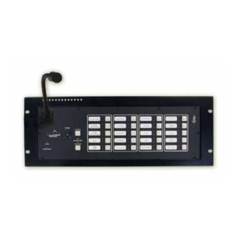
SMC02G/SMC02F/Variants - Product Manual Description The SMC02G and SMC02F are robust flush mounting Station Master’s Consoles suitable for mounting in 19” DIN equipment racks or other flat surfaces. The SMC02G has a panel mounted gooseneck microphone with a console mounted Push To Talk switch, and the SMC02F has a fist microphone with integral Push To Talk switch. -
Page 6: Operation
SMC02G/SMC02F/Variants - Product Manual Operation Control and Indicators Figure 1 SMC02 Front Panel SMC02G/SMC02GS SMC02F/SMC02FS Issue: 02 complete, approved Page 6 of 60... - Page 7 SMC02G/SMC02F/Variants - Product Manual Microphone • SMC02G and SMC02GS: Gooseneck microphone • SMC02F and SMC02FS: Fist microphone with integral Push To Talk button SPEECH LEVEL METER A LED bargraph speech level meter where the LEDs light in turn to indicate the sound pressure being received at the microphone.
- Page 8 PUSH TO TALK BUTTON The Press To Talk (PTT) button is integral to the fist microphone on SMC02F units, and fitted onto the microphone console on SMC02G units. When pressed, it activates the zone selection, opens the microphone channel and triggers the pre-announcement chime (if selected at the Router) ready for the paging announcement.
-
Page 9: Console Operation
SMC02G/SMC02F/Variants - Product Manual Console Operation 2.2.1 Live Announcements If using a SMC02F unit unhook the microphone from its retaining clip. ALL CALL ONLY When a standard SMC02 microphone is in All Call NORMAL PAGING MODE Only failsafe override mode, care should be taken... - Page 10 SMC02G/SMC02F/Variants - Product Manual Select the required zone(s) by pressing the appropriate Zone Select buttons (zones may be added or removed as required by pressing the buttons in turn). To deselect a selected zone press the button again. The appropriate green SELECT LED(s) will flash to show each zone has been successfully selected.
- Page 11 SMC02G/SMC02F/Variants - Product Manual When the chime has finished (if programmed at the Router), the SPEAK NOW LED will illuminate. If no chime has been programmed then the SPEAK NOW LED will illuminate immediately. Once the SPEAK NOW LED has illuminated you can SPEAK NOW make the announcement.
-
Page 12: Routing Digital Voice Messages (Dva Routing Buttons)
SMC02G/SMC02F/Variants - Product Manual 2.2.2 Routing Digital Voice Messages (DVA Routing Buttons) The ‘DVA Routing’ button function enables simple control of a single broadcast route, or complex broadcasts to be set up. For instance when a button is pressed a route can be made that connects any desired combination of audio inputs to any combination of outputs. - Page 13 SMC02G/SMC02F/Variants - Product Manual Select the required routing by pressing the appropriate BUSY Zone Select button programmed for DVA Routing. ROUTING BUTTON The green SELECT LED will illuminate to show that the SELECT route is active. LOUDSPEAKER The DVA and other audio sources programmed will then play at the programmed zones.
-
Page 14: Playing Digital Voice Messages (Play Dva Buttons)
SMC02G/SMC02F/Variants - Product Manual 2.2.3 Playing Digital Voice Messages (Play DVA Buttons) The button function is ‘play DVA to selected outputs’. When the button is pressed a route is made connecting a DVA audio source from the Slave Unit or the Audio Control Unit (ACU) to outputs which have been pre- selected using buttons configured for zone selection. - Page 15 SMC02G/SMC02F/Variants - Product Manual Select the required zone(s) by pressing the appropriate Zone Select buttons (zones may be added or removed as required by pressing the buttons in turn). To deselect a selected zone press the button again. The appropriate green SELECT LED(s) will flash to show each zone has been successfully selected.
- Page 16 SMC02G/SMC02F/Variants - Product Manual Stopping One DVA Message in All Zones A DVA message can either be ended with a reset button, or with the trigger button. To terminate a DVA message in all zones in which it is playing: PLAY •...
-
Page 17: Listen-In Operation
SMC02G/SMC02F/Variants - Product Manual 2.2.4 Listen-in Operation 2.2.4.1 Listen-in All Mode In Listen-in All mode the audio of all zones are mixed and fed to the listen-in speakers on all of SMC units controlled by the Router. Activate the listen-in function by pressing the PA LISTEN button on the primary SMC02 unit. -
Page 18: Selective Listen-In Mode
SMC02G/SMC02F/Variants - Product Manual 2.2.4.2 Selective Listen-In Mode In Selective Listen-in mode the audio of selected zones are mixed and fed to the listen-in speakers on all off SMC units controlled by the Router. Activate the selective listen-in function by holding down... -
Page 19: Installation
SMC02G/SMC02F/Variants - Product Manual Installation Installation Requirements 3.1.1 Equipment and Tool Requirements • The SMC02 unit. • SMC02 connection cable: ASL SMCLEAD-5M, SMCLEAD-20M, or parts to assembly such a cable. • Suitable marshalling box for connecting the site wiring to the SMC02 connection cable. -
Page 20: From Marshalling Box To Smc02 Console
SMC02G/SMC02F/Variants - Product Manual 3.1.2.2 From Marshalling Box to SMC02 Console The ASL SMCLEAD is built according to the requirements below, and can be ordered separately from Application Solutions Limited in two variants: • SMCLEAD-5M: Five metre long lead with marshalling box connections terminated in ferrules ready for connection. -
Page 21: Recommended Installation Procedure
SMC02G/SMC02F/Variants - Product Manual Recommended Installation Procedure Please read and observe the “Safety and Precautions” section on page of this manual. Produce the zone identification label as follows. a. Download the template file from the “Data Downloads” page of Application Solutions website: www.asl-electronics.co.uk/downloads. - Page 22 SMC02G/SMC02F/Variants - Product Manual Figure 3 SMC02 – Inserting the Zone Identification Labels LABEL BUTTONS 1-5 • Do not use any sharp tools, as they can damage the front panel. • Do not peel off the plastic cover. d. Re-fit the front panel back in place using the 11 off screws removed in step 3.a.
-
Page 23: Connections
SMC02G/SMC02F/Variants - Product Manual Connections Terminal Allocation Figure 4 SMC02 Terminal Allocation • SMC02 Console Connector (shown left): ITT NEPTUNE TNM 0S16-0019P1L fitted with T2P24MC1LT contacts • Mating Part (cable connector): ITT TNM 6S16-00191SL fitted with T2P24FC1LT contacts and TNA16CCSE00L end bell... -
Page 24: Connection Diagrams
SMC02G/SMC02F/Variants - Product Manual Connection Diagrams • Standard SMC02 (emergency microphone) units must be connected to Router’s Mic/Line inputs 1 or 2 as a ‘Zoned Fire Microphone’, in order to comply with BS5839 Pt 8. • ‘S’ variant SMC02 (non-emergency microphone) units can be connected to any Router’s Mic/Line inputs which support the required number of microphone buttons, and they are configured as ‘Paging Microphone’. -
Page 25: Fire Or Paging Microphone Connection To Var4/Var12/Var20 Input 1
SMC02G/SMC02F/Variants - Product Manual 4.2.1 Fire or Paging Microphone Connection to VAR4/VAR12/VAR20 Input 1 The following diagram shows the connection of the SMC02 to the VAR4/VAR12/VAR20’s Mic/Line input 1 as Zoned Fire Microphone or Paging Microphone, the latter being the only option for the ‘S’ variants. -
Page 26: Fire Or Paging Microphone Connection To Var4/Var12/Var20 Input 2
SMC02G/SMC02F/Variants - Product Manual 4.2.2 Fire or Paging Microphone Connection to VAR4/VAR12/VAR20 Input 2 The following diagram shows the connection of the SMC02 to the VAR4/VAR12/VAR20’s Mic/Line input 2 as a Zoned Fire Microphone or Paging Microphone, the latter being the only option for the ‘S’ variants. -
Page 27: Paging Microphone Connection To Other Var4/Var12/Var20 Inputs
SMC02G/SMC02F/Variants - Product Manual 4.2.3 Paging Microphone Connection to Other VAR4/VAR12/VAR20 Inputs The following diagram shows the connection of the SMC02 to other Mic/Line inputs of the VAR4/VAR12/VAR20 as a Paging Microphone. Figure 7 SMC02 Connection to Other VAR4/VAR12/VAR20’s Mic/Line Inputs... -
Page 28: Fire Or Paging Microphone Connection To Acu Input 1 Or 2
SMC02G/SMC02F/Variants - Product Manual 4.2.4 Fire or Paging Microphone Connection to ACU Input 1 or 2 The following diagram shows the connection of the SMC02 to an ACU’s Mic/Line input 1 or 2 as a Zoned Fire Microphone or Paging Microphone, the latter being the only option for the ‘S’ variants. - Page 29 SMC02G/SMC02F/Variants - Product Manual Figure 8 SMC02 Connection to ACU Inputs 1 or 2 ZONED FIRE MICROPHONE / PAGING MICROPHONE CONNECTIONS TO ACU INPUTS 1 OR 2 BMB01 SMC02 SERIAL RS485 RS485DXP PIN 50: DATA DXP FAULT LED RS485DXN PIN 51: DATA DXN...
-
Page 30: Paging Microphone Connection To Acu Inputs 3 To 8
SMC02G/SMC02F/Variants - Product Manual Paging Microphone Connection to ACU Inputs 3 to 8 The following diagram shows the connection of the SMC02 to an ACU’s Mic/Line inputs 3 to 8 as a Paging Microphone. Note the ACU can be either the wall mount Intellevac ACU or the rack mount VAR8-ACU. -
Page 31: Commissioning The Smc02
Menu: Configuration System Router Inputs Mic/Line <I/P #nn – MIC/LINE nn> Configure the SMC02 as: • Zoned Fire Microphone: for standard units (emergency microphone): SMC02F and SMC02G • Paging Microphone: for ‘S’ variants units (non-emergency microphone): SMC02FS and SMC02GS Issue: 02 complete, approved... -
Page 32: Configuring The Microphone Control Parameters
SMC02G/SMC02F/Variants - Product Manual Configuring the Microphone Control Parameters 5.3.1 Microphone Priority Menu: Configuration System Router Inputs Mic/Line <I/P #nn – MIC/LINE nn> <Zoned Fire Microphone or Paging Microphone> Ctrl Pri Possible priority levels: 01 to 19. 01 is the highest priority. -
Page 33: Microphone Name
SMC02G/SMC02F/Variants - Product Manual 5.3.3 Microphone Name Menu: Configuration System Router Inputs Mic/Line <I/P #nn – MIC/LINE nn> <Zoned Fire Microphone or Paging Microphone> Name Possible values: alphanumeric string of up to 12 characters System default configuration: ‘MIC/LINE nn’, where nn is the input number The Router associates a default name with the microphone input, which is 'MIC/LINE nn' (where nn is the Router’s input number). -
Page 34: Busy And Select Indication Leds Mode (Acu Only)
SMC02G/SMC02F/Variants - Product Manual 5.3.6 Busy and Select Indication LEDs Mode (ACU only) Menu: Configuration System Router Inputs Mic/Line <I/P #nn – MIC/LINE nn> <Zoned Fire Microphone or Paging Microphone> Ctrl LEDs Possible values: ‘Busy Standard’, or ‘Busy Class’ System default configuration: ‘Busy Class’ on Zone Fired Microphones ‘Busy Standard’... -
Page 35: Configuring The Ptt Button (Var4/Var12/Var20 Only)
SMC02G/SMC02F/Variants - Product Manual Configuring the PTT Button (VAR4/VAR12/VAR20 only) 5.4.1.1 PTT Button Cough Timeout (VAR4/VAR12/VAR20 only) Menu: Configuration System Router Inputs Mic/Line <I/P #nn – MIC/LINE nn> <Zoned Fire Microphone or Paging Microphone> Buttons Cough Possible values: 00 to 50 (Time in tenths of a second. Divide by ten for the time in seconds.) System default configuration: ‘0’... -
Page 36: Configuring The Listen-In Button
SMC02G/SMC02F/Variants - Product Manual Configuring the Listen-in Button 5.5.1.1 Listen-in Button Menu: Configuration System Router Inputs Mic/Line <I/P #nn – MIC/LINE nn> <Zoned Fire or Paging Microphone> Buttons <Button # nn> Switches Switch #4 Listen-in Possible values: ‘Not-Conf’, ‘Listen-in’, or ‘Security’ (not used for SMC02) System default configuration: ‘Not-Conf’... -
Page 37: Zone Selection Button
SMC02G/SMC02F/Variants - Product Manual 5.6.2 Zone Selection Button Menu: Configuration System Router Inputs Mic/Line <I/P #nn – MIC/LINE nn> <Zoned Fire Microphone or Paging Microphone> Buttons <Button # nn> MIC Routing The Microphone Routing button function is for zone selection, i.e. when pressed it selects a specified output or group of outputs to which the microphone audio is to be routed when the PTT button is subsequently pressed. -
Page 38: Controlled Route Or Routes
SMC02G/SMC02F/Variants - Product Manual 5.6.3.1 Controlled Route or Routes Menu: Configuration System Router Inputs Mic/Line <I/P #nn – MIC/LINE nn> <Zoned Fire Microphone or Paging Microphone> Buttons <Button # nn> DVA Routing Zoning It is necessary to define the route or routes that it controls, by associating an input to each available output. -
Page 39: Dva Play Mode
SMC02G/SMC02F/Variants - Product Manual 5.6.3.3 DVA Play Mode Menu: Configuration System Router Inputs Mic/Line <I/P #nn – MIC/LINE nn> <Zoned Fire Microphone or Paging Microphone> Buttons <Button # nn> DVA Routing Control DVA-Full or DVA-Part Possible values: ‘DVA-Full’, ‘DVA-Part’ System default configuration: ‘DVA-Full’... -
Page 40: Play Dva Button (Acu Only)
SMC02G/SMC02F/Variants - Product Manual 5.6.5 Play DVA Button (ACU only) Menu: Configuration System Router Inputs Mic/Line <I/P #nn – MIC/LINE nn> <Zoned Fire Microphone or Paging Microphone> Buttons <Button # nn> Play DVA The button function is ‘play DVA to selected outputs’. When the button is pressed a route is made connecting a DVA audio source from the Slave Unit or the Audio Control Unit (ACU) to outputs which have been pre- selected using buttons configured for zone selection. -
Page 41: Dva Play Mode
SMC02G/SMC02F/Variants - Product Manual • ‘Play Once’ mode Pressing a ‘Play DVA’ button plays the DVA associated with the route once only. When the DVA has completed its full message cycle, the route is terminated. Example is for a ‘Mind the Gap’ broadcast. -
Page 42: Configuring The Microphone Audio Parameters
SMC02G/SMC02F/Variants - Product Manual Configuring the Microphone Audio Parameters 5.7.1 Microphone Input Gain VAR4/12/20 Menu: Configuration System Router Inputs Mic/Line <I/P #nn – MIC/LINE nn> <Zoned Fire Microphone or Paging Microphone> Audio Gain PreAmp ACU/VAR8-ACU Menu: Configuration System Router Inputs Mic/Line <I/P #nn – MIC/LINE nn>... -
Page 43: Microphone Relative Output Gain (Var4/Var12/Var20 Only)
SMC02G/SMC02F/Variants - Product Manual 5.7.3 Microphone Relative Output Gain (VAR4/VAR12/VAR20 only) Menu: Configuration System Router Inputs Mic/Line <I/P #nn – MIC/LINE nn> <Zoned Fire Microphone or Paging Microphone> Audio Gain O/pGains Possible values: –40dB to 0dB (1dB steps) System default configuration: ‘0dB’... -
Page 44: Microphone Equalisation
SMC02G/SMC02F/Variants - Product Manual 5.7.4 Microphone Equalisation Menu: Configuration System Router Inputs Mic/Line <I/P #nn – MIC/LINE nn> <Zoned Fire Microphone or Paging Microphone> Audio EQ Possible values: –12dB to +12dB (1dB steps) System default configuration: ‘0dB’ A 3-band equaliser is provided on Mic/Line inputs in order to balance the input tone. This equaliser has a shelving HF (treble) adjustment, shelving LF (bass) adjustment, and a fixed MID section adjustment. - Page 45 SMC02G/SMC02F/Variants - Product Manual Figure 10 Sequence of Events for Single Audio Source MUSIC AUDIO MUSIC FADE UP=T1 FADE DOWN= T2 The diagram in Figure 11 illustrates the sequence of events during the override of a background music source by a Paging Microphone with chime.
-
Page 46: Microphone Pre-Annoucement Chime
SMC02G/SMC02F/Variants - Product Manual 5.7.6 Microphone Pre-Annoucement Chime Menu: Configuration System Router Inputs Mic/Line <I/P #nn – MIC/LINE nn> <Zoned Fire Microphone or Paging Microphone> Audio Chime Possible chime level: –40dB to 0dB (1dB steps) Possible chime types: ‘Chime-1’ (one chime) ‘Chime-2’: two chimes... -
Page 47: Configuring The System Fault Indication Control
SMC02G/SMC02F/Variants - Product Manual Configuring the System Fault Indication Control 5.8.1 Remote Fault Output (VAR4/VAR12/VAR20 only) Menu: Configuration System Router Misc Fault Fault Outputs Fault Outputs REMOTE FAULT O/P <i> Remote Fault Active Indicator The System Fault LED on the SCM02 console is connected to one of the VAR4/VAR12/VAR20’s Remote Fault Outputs. -
Page 48: Fault Finding
SMC02G/SMC02F/Variants - Product Manual Fault Finding Table 2 SMC02 Faults – VAR4/VAR12/VAR20 Fault Code(s) Operational Fault Fault Reported and Suggested Action Symptom Description Logged at the VAR4/VAR12/VAR20 Total loss of live audio Input audio IPXX AUDIO INPUT • Check audio cabling or power supply... - Page 49 SMC02G/SMC02F/Variants - Product Manual Table 3 SMC02 Faults – Intellevac ACU and VAR8-ACU Fault Code(s) Reported and Logged Operational Fault Fault Suggested Action at the Symptom Description Intellevac ACU and VAR8-ACU • Check audio cabling or power supply Total loss of live audio...
-
Page 50: Maintenance
SMC02G/SMC02F/Variants - Product Manual Maintenance The SMC02 should be tested with the PA/VA system for correct operation, at maximum intervals of three months and as part of the system maintenance schedule. Issue: 02 complete, approved Page 50 of 60... -
Page 51: Product Specification
Microphone Control Data..................EIA RS485 / 19200 baud Listen-in Audio....................–10 dBu balanced (nominal) Buttons........................20 Zone Select Buttons PTT button on console (SMC02G) PTT button on fist microphone (SMC02F) Listen-in button LEDs ............2 LEDs per zone Select button (zone Busy and zone Selected) - Page 52 SMC02G/SMC02F/Variants - Product Manual Safety and EMC EN55103-1/E1, EN 55103-2/E5, EN50121-4, ENV50204 EN61000-4-3 (80 MHz to 1 GHz) / EN61000-4-6 (0.15 MHz to 80 MHz) ......ITU/R 562-3 Impairment level 3 In the close proximity to some radio frequency transmitters, the signal to noise ratio of this system may be reduced.
-
Page 53: Mechanical Dimensions
SMC02G/SMC02F/Variants - Product Manual Mechanical Dimensions Figure 12 Cutout Details BASIC CASE DIMENSIONS ENSURE CLEARANCE FOR SPEAKER GRILL 483 mm 100 mm 87.5 mm 465 mm 76.5 mm ALLOW AT LEAST 100 MM FOR MATING CONNECTOR AND CABLE RECOMMENDED CUTOUT DIMENSIONS 232.5 mm... - Page 54 SMC02G/SMC02F/Variants - Product Manual Figure 13 Mechanical Dimensions 95 mm 55 mm 13.7 mm 14 mm 25.5 mm 17.5 mm 6 mm 35 mm 35 mm 413 mm 12 mm 47.9 mm 436 mm 483 mm THIRD ANGLE PROJECTION Issue: 02 complete, approved...
-
Page 55: Safety And Precautions
SMC02G/SMC02F/Variants - Product Manual Safety and 10.4.1 Packing for Return for Repair Precautions All electronics assemblies must be properly packed in ESD protective packing for transport, to prevent 10.1 Environmental physical and ESD damage. Use of non-ESD protective packing for return... -
Page 56: Spare Parts And Accessories
SMC02G/SMC02F/Variants - Product Manual Spare Parts and Accessories Table 4 SMC02 Spare Part List ASL Part Number Additional Information SMCLEAD-5M SMC02 Lead – 5 metres, with ferrules termination Function: Connects the SMC02 to marshalling box. Location: Bottom of SMC02 Back Box Manufacturer/Supplier: Application Solutions Limited Manufacturer/Supplier Part No.: SMCLEAD-5M... -
Page 57: Reference Documents
SMC02G/SMC02F/Variants - Product Manual Reference Documents Additional reference information may be found in the following documentation, available from the “Data Downloads” page of Application Solutions website: www.asl-electronics.co.uk Table 5 Reference Documents Ref. No Title Filename Ref Origin VAR Router Product Description... -
Page 58: Index
SMC02G/SMC02F/Variants - Product Manual Index audio parameters ....... 42, 44, 46 button capacity ..........33 cancel all dvas button........41 annotation label ............8 chime.............. 46 announcement class ............... 32 chime...............10 control parameters ......... 32 dva routing button .......... 37 equalisation ............ 44 background music..........45... -
Page 59: Service And Warranty
SMC02G/SMC02F/Variants - Product Manual Service and Warranty Name and Address of Authorised Distributor: This product carries a full warranty. For full details of warranty and service agreements, please contact the Authorised Distributor who supplied the product to you. Exclusions The warranty does NOT cover: Customer misuse, including incorrect installation.
Need help?
Do you have a question about the SMC02G and is the answer not in the manual?
Questions and answers