Table of Contents
Advertisement
Quick Links
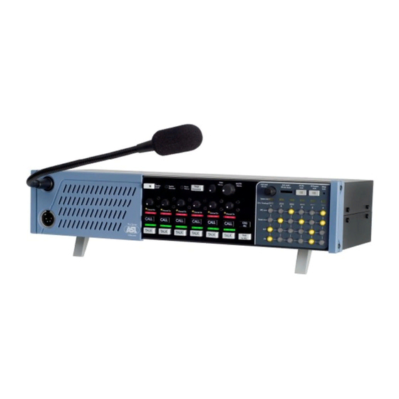
SIX CHANNEL LOUDSPEAKER MASTER STATION
PRO SERIES
USER MANUAL
FOR THE
PS 6379
CONTENTS
1.0
SAFETY INSTRUCTIONS.....................................3
2.0
GENERAL DESCRIPTION..........................................4
3.0
UNPACKING ...............................................................4
4.0
MECHANICAL INSTALLATION...................................4
5.0
MAINS POWER ...........................................................5
6.0
FRONT PANEL CONTROLS....................................6-9
7.0
REAR PANEL CONTROLS ..................................10-11
8.0
INTERNAL CONTROLS.......................................12-14
9.0
MODES .....................................................................15
10.0
CABLING ..................................................................16
11.0
PARTY LINE, TECHNICAL CONCEPT .....................17
12.0
WARRANTY..............................................................17
13.0
TECHNICAL SPECIFICATIONS ...............................17
14.0
DESIGN CRITERIA...................................................18
1
Advertisement
Table of Contents

Related Manuals for ASL INTERCOM PS 6379


Summary of Contents for ASL INTERCOM PS 6379
-
Page 1: Table Of Contents
REAR PANEL CONTROLS ........10-11 INTERNAL CONTROLS........12-14 MODES ..............15 10.0 CABLING ..............16 11.0 PARTY LINE, TECHNICAL CONCEPT .....17 12.0 WARRANTY..............17 13.0 TECHNICAL SPECIFICATIONS .......17 User manual PS 6379 / Issue 1 © 2006 ASL Intercom, Utrecht, The Netherlands 14.0 DESIGN CRITERIA...........18... - Page 2 User manual PS 6379 / Issue 1 © 2006 ASL Intercom, Utrecht, The Netherlands...
-
Page 3: Safety Instructions
User manual PS 6379 / Issue 1 © 2006 ASL Intercom, Utrecht, The Netherlands... -
Page 4: General Description
A special kit is included for mounting the PS 6379 in a 19" professional flexible microphone cable with 2 wires and rack, taking 2U of rack-space. User manual PS 6379 / Issue 1 © 2006 ASL Intercom, Utrecht, The Netherlands... -
Page 5: Mains Power
The unit has a switch mode power supply and accepts mains voltages from 100 – 240 VAC (50 / 60 Hz). Mains Fuse For all voltages : T 1250. User manual PS 6379 / Issue 1 © 2006 ASL Intercom, Utrecht, The Netherlands... - Page 6 8.0) in which case each unit will use its own After the CALL button is released the LEDS will Stage Announce output and microphone. continue to flash for further 2 seconds. 4 TALK to ALL User manual PS 6379 / Issue 1 © 2006 ASL Intercom, Utrecht, The Netherlands...
- Page 7 It prevents the speaker from feeding back into the gooseneck microphone (unit feedback). For adjustment procedure see above in point 9. User manual PS 6379 / Issue 1 © 2006 ASL Intercom, Utrecht, The Netherlands...
-
Page 8: Front Panel Controls
PS 6379 can be muted. auxiliary, see point 17 AUX Level / IFB DIM. The buzzers stay muted until the ALL BUZZER MUTE button is switched off again. User manual PS 6379 / Issue 1 © 2006 ASL Intercom, Utrecht, The Netherlands... - Page 9 If no IFB-Auxiliary is needed, it can be switched the PS 6379 on the channel which is in system link. If a Mic off by switching off the aux button of that channel. The...
-
Page 10: Rear Panel Controls
6379 to the remote stations, via standard microphone line level. cable. There are two connectors for each channel. Pin assignments: 1. 0V / ground 2. +30 V power wire 3. Audio wire User manual PS 6379 / Issue 1 © 2006 ASL Intercom, Utrecht, The Netherlands... -
Page 11: Rear Panel Controls
42 MAINS POWER CONNECTION Mains inlet with built in fuse holder. 90 –240 V AC, 50 – 60 Hz. Power consumption 200 Watt, Fuse: 4 Amp slow blow. User manual PS 6379 / Issue 1 © 2006 ASL Intercom, Utrecht, The Netherlands... - Page 12 No. 2 CALL RECEIVE Channel B channels. (For PAGING functions see section (factory setting = ‘off’) (Same as for No. 6) 9.0 MODES) No. 1 CALL RECEIVE Channel A User manual PS 6379 / Issue 1 © 2006 ASL Intercom, Utrecht, The Netherlands...
- Page 13 (See section 9 MODES). If the dip switch is in ‘off’ position, the gooseneck or headset microphone and the Stage Announce output of the master unit is used. If the dip User manual PS 6379 / Issue 1 © 2006 ASL Intercom, Utrecht, The Netherlands...
-
Page 14: Internal Controls
45 HEADSET MIC GAIN This trimmer controls the gain of the headset microphone. 46 GOOSENECK MIC GAIN This trimmer controls the gain of the gooseneck microphone. User manual PS 6379 / Issue 1 © 2006 ASL Intercom, Utrecht, The Netherlands... -
Page 15: Modes
To connect 2 stations as “NEAR STATIONS’, a Near Station 379 A link cable is needed. To connect 3 stations you need a Near Station 379 A and a Near Station 379 B cable. User manual PS 6379 / Issue 1 © 2006 ASL Intercom, Utrecht, The Netherlands... -
Page 16: Cabling
See Party Line, Technical Concept User manual PS 6379 / Issue 1 © 2006 ASL Intercom, Utrecht, The Netherlands... -
Page 17: Party Line, Technical Concept
0.1 sec Note: 0 dBu = 775 mV into open circuit ASL reserve the right to alter specifications without further notice. User manual PS 6379 / Issue 1 © 2006 ASL Intercom, Utrecht, The Netherlands... -
Page 18: Design Criteria
Negative effects in the performance of beltpacks can be avoided when keeping them at a safe distance from equipment which might radiate strong electro-magnetic fields, such as transmitters antennas and dimmers. User manual PS 6379 / Issue 1 © 2006 ASL Intercom, Utrecht, The Netherlands... - Page 19 User manual PS 6379 / Issue 1 © 2006 ASL Intercom, Utrecht, The Netherlands...
- Page 20 User manual PS 6379 / Issue 1 © 2006 ASL Intercom, Utrecht, The Netherlands...
Need help?
Do you have a question about the PS 6379 and is the answer not in the manual?
Questions and answers