Table of Contents
Advertisement
Quick Links
Advertisement
Table of Contents

Related Manuals for ASL INTERCOM BS 15


Summary of Contents for ASL INTERCOM BS 15
- Page 1 BS 15 SINGLE CHANNEL BELTPACK USER MANUAL Issue 2011 © ASL Intercom BV DESIGNED & MANUFACTURED BY: ASL Intercom B.V. Zonnebaan 42 3542 EG Utrecht The Netherlands Tel: +31 (0)30 2411901 Fax: +31 (0)30 2667373 Email: info@asl-inter.com Web: www.asl-inter.com...
-
Page 2: Table Of Contents
PARTY LINE, TECHNICAL CONCEPT ...... 5 10.0 CABLING ........... 6 11.0 EARTHING CONCEPT ......... 7 12.0 SYSTEM CONFIGURATION ......7 13.0 BLOCK DIAGRAM BS 15 ....... 8 PAGE 2 User Manual BS 15 / Issue 2011 © ASL Intercom BV... -
Page 3: General Description
Please also refer to the guarantee section of this manual. INSTALLATION This BS 15 will form part of an existing or new Connect the system intercom cable to the LINE intercom system, and connection to it is connector on the rear panel. Finally connect the straightforward. -
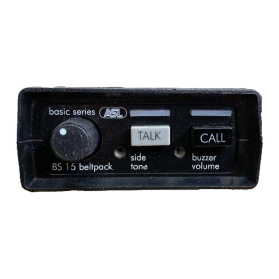
Page 4: Front Panel Controls
This push button activates the call system. By a momentary push a call signal is sent to all button of this BS 15 (or a CALL button of any stations connected to the intercom channel and other station on the channel to which the BS 15 is the call LED’s start flashing. -
Page 5: Internal Controls
XLR pin 3 and 1), a signal voltage is developed impedance which will be sensed by each station which can be further amplified and sent to the and interpreted as a Call signal. headphones. PAGE 5 User Manual BS 15 / Issue 2011 © ASL Intercom BV... -
Page 6: Cabling
10.0 CABLING The intercom lines (the ‘party lines’) are of the shielded two-conductor microphone cable type. The intercom line connectors are of the XLR-3 type. Audio and Call signals are on pin 3, DC power is on pin 2 and pin 1 is connected to the shield of the cable which functions as the common return for audio and power. -
Page 7: Earthing Concept
11.0 EARTHING CONCEPT 12.0 SYSTEM CONFIGURATION PAGE 7 User Manual BS 15 / Issue 2011 © ASL Intercom BV... -
Page 8: Block Diagram Bs 15
13.0 BLOCK DIAGRAM BS 15 PAGE 8 User Manual BS 15 / Issue 2011 © ASL Intercom BV...
Need help?
Do you have a question about the BS 15 and is the answer not in the manual?
Questions and answers