Table of Contents
Advertisement
Advertisement
Table of Contents

Related Manuals for ASL INTERCOM BS 217


Summary of Contents for ASL INTERCOM BS 217
- Page 1 BS 217 HANNEL ASTER TATION User Manual December 2016 V1.0...
-
Page 2: Table Of Contents
Table of contents 1.0 SAFETY INSTRUCTIONS .................... 3 2.0 GENERAL DESCRIPTION BS 181 .................. 4 3.0 MECHANICAL INSTALLATION .................. 5 4.0 MAINS POWER & SAFETY EARTH ................ 6 5.0 FRONT PANEL CONTROLS & CONNECTOR .............. 7 6.0 REAR PANEL CONTROLS & CONNECTORS .............. 9 7.0 TECHNICAL SPECIFICATIONS ..................10 8.0 BS 217 BLOCK DIAGRAM ..................11 9.0 PARTY LINE, TECHNICAL CONCEPT ................12 10.0 CABLING ......................... 12 11.0 POSSIBLE SYSTEM CONFIGURATION . -
Page 3: Safety Instructions
SAFETY INSTRUCTIONS Please always follow these instructions to help ensure against injury to yourself and/or damage to the system 1. Read all safety and operating instructions before you operate the apparatus. 2. Retain all safety and operating instructions for future reference. 3. -
Page 4: General Description Bs 181
GENERAL DESCRIPTION BS 181 The BS 217 (19”/1RU) is designed to be a dual channel master station in an ASL intercom system. Master station and remote stations are interconnected by standard microphone cable. -
Page 5: Mechanical Installation
MECHANICAL INSTALLATION For the BS 217 a vertical rack space of 1RU (1.75”, 44mm) is required. It is not necessary to provide rear support by extra bracing or shelving. Adequate ventilation must be pro- vided by allowing sufficient space around the sides and rear of the unit to ensure free circulation of air. -
Page 6: Mains Power & Safety Earth
MAINS POWER & SAFETY EARTH The BS 217 may be connected to a mains power outlet which provides 100 – 240 V AC, 50- 60 Hz and at least 60 watts. The outlet should have a clean earth. Avoid using mains power outlets which also power dimmer controlled lighting equipment. -
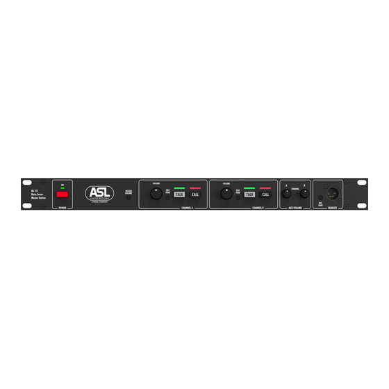
Page 7: Front Panel Controls & Connector
FRONT PANEL CONTROLS & CONNECTOR POWER ON/OFF switch Mains power push button to switch the internal power supply on or off. MAINS POWER LED This LED illuminates if line power is supplied by the internal power supply. BUZZER VOLUME trimmer To adjust the volume of the buzzer. - Page 8 TALK buttons + LEDs channel A & B These buttons allow the user to talk to each channel separately or to both channels simultaneously. The large green LED’s indicate if the talk function is activated. CALL buttons + LEDs channel A & B A Call button activates the Call system.
-
Page 9: Rear Panel Controls & Connectors
REAR PANEL CONTROLS & CONNECTORS INTERCOM LINE connectors for Channels A & B These XLR-3 type connectors are for connecting remote stations, using standard microphone cable. There are 2 connectors for channel A and 2 connectors for channel B. Pin assignments: Pin 1: 0V / ground shield Pin 2: +30V DC power wire Pin 3: audio wire... -
Page 10: Technical Specifications
TECHNICAL SPECIFICATIONS System Specifications • dynamic range: 80 dB (1 kHz, THD < 1%) • frequency response: 200 Hz – 15 kHz (-3 dB) • call signal (send): 2.8 mA • call signal threshold (receive): +2.4 V DC • operating voltage: 24 - 32 V DC Intercom Line •... -
Page 11: Bs 217 Block Diagram
BS 217 Dimensions & Weight Width: 19” (483 mm) • Height: 1RU (44.5 mm) • Depth: 140 mm • Weight: 1.75 Kg • 0 dB is defined as 775 mV into open circuit ASL reserves the right to alter specifications without prior notice... -
Page 12: Party Line, Technical Concept
PARTY LINE, TECHNICAL CONCEPT User stations and power supplies in an ASL intercom system are connected via one or several 'party lines'. A party line offers two-way (‘full duplex’) communication and consists of standard micro- phone (multi-pair) cable. One wire is used as an audio line, one as a power line and the screen of the cable functions as earth/return. - Page 13 Use high quality cable Use high quality microphone cable (shielded two conductor cable, minimum 2x 0.30 mm2). In case multi-pair microphone cable is used, there should be an overall shield and each pair should consist of two conductors (minimum 2x 0.15 mm2) with separate shield Use flexible cable Use flexible single and multi-pair microphone cable instead of cable with solid cores, especially when the cable is subjected to bending during operation or installation.
-
Page 14: Possible System Configuration
ASL powered units to a 'clean' mains outlet Master stations or power supplies should be connected to a mains outlet with a clean earth. Other audio equipment may be connected to this mains outlet, but avoid using an outlet which also powers dimmer controlled lighting systems. -
Page 15: Earthing Concept
12.0 EARTHING CONCEPT Designed and manufactured by: ASL Intercom BV Zonnebaan 42, 3542 EG Utrecht, The Netherlands Phone: +31 (0)30 2411901 Fax: +31 (0)30 2667373 ⎪ E-mail: info@asl-inter.com www.asl-inter.com Web: ⎪...
Need help?
Do you have a question about the BS 217 and is the answer not in the manual?
Questions and answers