Extron electronics TLP 700MV Setup Manual
Extron tlp 700mv touchlink panel setup guide
Hide thumbs
Also See for TLP 700MV:
- User manual (58 pages) ,
- User manual (52 pages) ,
- Setup manual (4 pages)
Advertisement
Table of Contents
- 1 Overview
- 2 TLP 700MV Front Panel Features
- 3 Mounting the TLP 700MV
- 4 Configuring the TLP 700MV (Initial Setup)
- 5 Calibration Menu
- 6 Reset Modes
- 7 Designing the TLP 700MV Interface with GUI Configurator
- 8 Configuring the TLP 700MV Interface with Global Configurator 3
- Download this manual
See also:
User Manual
TLP 700MV Setup Guide
Overview
The Extron
TLP 700MV is a wall-mounted TouchLink
®
provides simple and versatile configuration and control for a range
of IP Link
®
control systems.
Graphic and text objects are displayed on the screen. These objects
have system control functions associated with them and the touch
overlay allows you to activate or regulate those functions.
The TLP 700MV communicates with the configurable IP Link controller through an Ethernet connection to an IP Link device.
Two BNC connectors allow the screen to be used to preview composite video or S-video.
NOTE: The RJ-45 output on the rear panel of the TLP 700MV must be connected to a network switch, hub, or router that
is connected to an Ethernet LAN or the Internet. An Extron IP Link controller must also be connected to the same
network. Suggested models include IPL T S series (for example, IPL T S4), IPL 250, IPL T CR 48, or IPL T SFI 244 .
This guide provides basic instructions for experienced installers to mount and perform initial configuration on the TLP
700MV. Full instructions and reference material can be found in the TLP 700MV and TLP 700TV User Guide, which is
available on the Extron Web site (
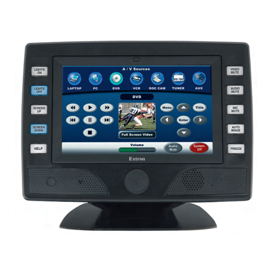
TLP 700MV Front Panel Features
1
LIGHTS
ON
LIGHTS
OFF
SCREEN
SCREEN
HELP
?
2
3
Figure 1.
TLP 700MV Front Panel (left) and Front Panel with Bezel Removed to Show Recessed Buttons (right).
a
Buttons — These ten backlit push-buttons (five on either side of the screen) can be configured, using the Extron Global
Configurator software, to control commonly used functions.
b
Motion Detector — This detector is capped with a small Fresnel lens that focuses light onto the sensor. When no motion
has been detected for a user-defined period of time, the unit goes into sleep mode. When motion is detected in the
vicinity of the panel, the screen display is restored and all buttons are active.
c
Encoder Knob — This knob is used for volume control.
d
Light Sensor — This sensor monitors the level of ambient light and adjusts the screen brightness and button
backlighting.
e
LCD screen — This 800 x 480 resolution LCD screen has a touch overlay. The Extron GUI Configurator software is used
to design a graphic user interface, which displays buttons, text, or icons on the screen. The Extron Global Configurator
software is used to program these screen objects to perform user-defined functions.
f
Speaker — A single 2 W speaker provides audible feedback for the user.
g
Reboot button — This button is recessed behind the bezel. It shuts down and restarts the unit without changing any of
the parameters.
h
Reset button — This button is recessed behind the bezel and is used to select from the four different reset modes that
are available with TouchLink panels (see "Reset Modes" later in this guide).
i
Menu button — This button is recessed behind the bezel. It activates the on-screen menus for setting up the panel and
calibrating the unit.
j
Reset LED — This LED is recessed behind the bezel. It is visible only when the faceplate has been removed. It lights as an
indicator for the Reset modes.
Panel that
™
www.extron.com
).
4
DISPLAY
MUTE
AUDIO
MUTE
SPEECH
5
MUTE
AUTO
IMAGE
FREEZE
6
LIGHTS
ON
LIGHTS
OFF
SCREEN
SCREEN
HELP
?
DISPLAY
MUTE
AUDIO
MUTE
SPEECH
MUTE
AUTO
IMAGE
FREEZE
7
8
9
10
Advertisement
Table of Contents

Subscribe to Our Youtube Channel
Related Manuals for Extron electronics TLP 700MV


Summary of Contents for Extron electronics TLP 700MV
- Page 1 Two BNC connectors allow the screen to be used to preview composite video or S-video. NOTE: The RJ-45 output on the rear panel of the TLP 700MV must be connected to a network switch, hub, or router that is connected to an Ethernet LAN or the Internet. An Extron IP Link controller must also be connected to the same network.
- Page 2 This optional part can be used with other TouchLink panel accessories (see for details). To mount the TLP 700MV in the wall, follow these instructions and see the figure below. The steps can be easily adapted if the unit is mounted in furniture (such as a podium or table).
-
Page 3: Setup Menu
Configuring the TLP 700MV (Initial Setup) Before using the TLP 700MV, it is essential to configure it using the on-screen menus. There are five different screens (Main, Volume, Time, Network, and Video) that can be selected by pressing the appropriate button at the left side of the screen. - Page 4 NOTE: Consult the GUI Configurator help file for information about using GUI Configurator. To open the help file, click on the Help menu and select Contents or press the F1 button on your keyboard. Configuring the TLP 700MV Interface with Global Configurator 3 Install the Global Configurator 3 software on a PC and use it to assign functions to the screen elements that were created with GUI Configurator.
Need help?
Do you have a question about the TLP 700MV and is the answer not in the manual?
Questions and answers