Table of Contents
Advertisement
Quick Links
Advertisement
Table of Contents

Related Manuals for Ganz ZR-DHC830NP


Summary of Contents for Ganz ZR-DHC830NP
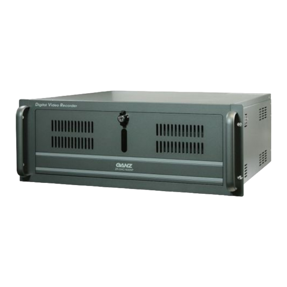
- Page 1 ZR-DHC830NP/ZR-DHC1630NP...
- Page 2 Notice This manual applies to the ZR-DHC1630NP/ZR-DHC830NP only. This manual describes the external features of the ZR-DHC1630NP/ZR-DHC830NP, part names, correct connection methods for supported domes or pan/tilt receivers, control devices, peripheral devices and the system setup instructions. It is important to note here that some features, figures, pictures and references can only be applied to just one model: ZR-DHC1630NP/ZR-DHC830NP.
- Page 3 Copyrights Copyrights Copyrights All copyrights of this manual are reserved by CBC Co., Ltd. © Copyright 2006 Any reproduction or republishing of this manual for commercial purposes is prohibited. It is prohibited to transfer this manual via online media such as, but not limited to, the Internet.
- Page 4 Caution Please be aware of the following precautions before installing the DVR. • Avoid positioning the ZR-DHC1630NP/ZR-DHC830NP in any place where the unit may come into contact with moisture, dust, or soot. • Avoid placing in direct sunlight or near heating appliances.
- Page 5 Safety Warnings and Cautions Safety Warnings and Cautions Safety Warnings and Cautions The following are warnings and cautions to ensure user safety and prevent property damage. Please read the information below thoroughly. Warning and caution signs If you are not aware of this If you are not aware of this Warning Caution...
- Page 6 Warning Do not attempt to disassemble, repair or modify Install the system in a cool place without direct sunlight and always maintain room temperature. the system on your own. It is extremely dangerous due to high voltage running through Avoid candlelight and heat-generating devices such as a heater.
- Page 7 Warning Power setup Connect with AC115V if the Connect with AC230V if the AC selector appears as AC selector appears as shown shown here. here. Caution Do not install the system in an area featuring high Install the system in a place with appropriate magnetic, electric wave or wireless devices such moisture and temperature levels.
- Page 8 Caution The system can be damaged as a result of strong The outlet must be placed on the ground. impact or vibration. Avoid throwing objects within the vicinity of the system. If there is strange sound or smell, unplug the Avoid direct sunlight or any heating appliances.
-
Page 9: Table Of Contents
Index Index User Manual 1. Installation System front panel ……………..………………………………………………………12 System back panel ……………….…………………………………………………13 Basic connection …………………………………………………………………………15 Alarm-in connection………………..……………………………………………………16 Alarm-out connection ……………….…………………………………………………17 RS485 port connection ……………..………………………………………………… 18 Network connection …………………………………………………………………19 2. Live Live screen ………………..……………….………………………………………20 Login menu ……………..………………………………………………………………22 Picture composition ………………..……………………………………………………23 2. - Page 10 3. Configuration 3 . 1 H a r d w a r e … … … … … … … … … … … … . . … … … … … … … … … … … … … … … … … 4 1 3 .
- Page 11 5. Advanced search 5 . 1 E v e n t s e a r c h … … … … … … … … … … … … … … … … … … … … … … … … … 1 1 0 5 .
-
Page 12: Installation
1. Installation 1.1 System front panel 1.1 System front panel Door Closed USB Port CD/DVD-RW Door Open Power Switch [Note] ☞ ☞ • This manual is written based on the 16 channel DVR (Model : ZR-DHC1630NP). The contents may change according to the number of channels and the types of exterior equipment. -
Page 13: System Back Panel
1.2 System back panel 1.2 System back panel ZR-DHC1630NP ZR-DHC1630NP 13 14 Power Supply (AC 100-120/200-240V, 50/60HZ, 10-5.5A) Alarm Input (16-Port) SPOT Monitor Output (2-Port) Camera Input (16-Port) RS485 Port Alarm Output (4-Port) Audio Input Port Mouse Input Port (PS/2) Keyboard Input Port (PS/2) Printer Port (LPT1) Serial Port (COM1) - Page 14 ZR-DHC830NP ZR-DHC830NP Power Supply (AC 100-120/200-240V, 50/60HZ, 10-5.5A) Alarm Input (16-Port) SPOT Monitor Output (2-Port) Camera Input (16-Port) RS485 Port Alarm Output (4-Port) Audio Input Port Mouse Input Port (PS/2) Keyboard Input Port (PS/2) Printer Port (LPT1) Serial Port (COM1) USB Port (Ver.
-
Page 15: Basic Connection
1.3 Basic connection 1.3 Basic connection The devices and cables should be connected to the back panel as shown above. Connecting the power cable to the power supply. [Warning] • The power cable should be plugged in after all devices are connected. The system will automatically boot once the power cable is plugged in. -
Page 16: Alarm-In Connection
1.4 Alarm in connection 1.4 Alarm in connection Input alarm- Input alarm- in no. 1 in no. 9 When an event occurs, the sensor device should open or close a mechanical connection to form a circuit to inform the DVR that it has been activated. The mechanical switch can connect with either a GND or an alarm input. -
Page 17: Alarm-Out Connection
1.5 Alarm out connection 1.5 Alarm out connection The DVR System can turn an alarm device such as a siren or a light on or off. The Alarm device can connect to the alarm output and COM terminals. Each alarm output terminal can be setup as NC (Normal Close) or NO (Normal Open) in the system configuration. -
Page 18: Rs485 Port Connection
1.6 RS485 port connection 1.6 RS485 port connection The DVR System and the PTZ device can be controlled using the RS485 interface. The RS485 terminal is provided in the DVR system can be used to control the PTZ camera, speed dome and other external devices. -
Page 19: Network Connection
1.7 Network connection 1.7 Network connection UTP Cable (CAT5) LAN/WAN internet Switch hub (100Mbps) Router The DVR system support includes the remote control, remote search and remote S/W upgrade by network. When setting up the network, it is recommended to use the switch hub with TCP/IP protocol for LAN/WAN. -
Page 20: Live
. Live 2.1 Live screen 2.1 Live screen The search picture provides a variety of split and whole screen displays. It can control the PTZ, which is connected to the selected camera and 1ch instant playback. You can also enter the search and system setup menus. - Page 21 Alarm-In : It indicates which sensors are connected to the DVR system. Time Display : Shows the GANZ logo and the current time and date. System condition Window : Displays the HDD capacity % used and a light to indicate the USB/overwrite/network status.
-
Page 22: Login Menu
2.2 Login menu 2.2 Login menu After setting up the user ID and password, you can control the authorization of the other users in the search and setup menus as well as the availability of other functions. Login Login 1. Click on the “Login” button. 2. -
Page 23: Picture Composition
2.3 Picture composition 2.3 Picture composition Picture composition Picture composition [C01] CAMERA01 REC : M Camera Mark : Display for camera motion and normal or PTZ camera. : Stands for a normal camera. : Stands for a PTZ camera. Camera number : Display for the channel number. Camera name : Display for the camera name. -
Page 24: System Status
2.4 System status 2.4 System status System status System status Hard disk storage : The size of the hard disk and percentage used are displayed. HDD usage diagram color will change to red after 90% full. Click on the icon to enter the Database allocation menu. (As Below) b USB connectivity : Displays if a USB device is connected. - Page 25 Recording process: Displays if the DVR is overwriting on the storage One-time recording : Gray. Overwrite recording : Red. CMS connect : Displays if CMS remote software is connected. CMS connected : Blue. CMS not connected : Gray.
-
Page 26: Db Drive Allocation
2.5 DB drive allocation 2.5 DB drive allocation New DB drive allocation New DB drive allocation 1. Using the administration login, double-click on the icon. 2. The following DB Allocation window will be displayed. 3. When a mouse is left-clicked on “Free Size” as indicated by the red square above, the following message window will be displayed: “Do you want to format?”. - Page 27 DB drive storage release or free space DB drive storage release or free space 1. In order to remove an allocated DB drive, right-click on the drive as shown below. If the drive is allocated, this is indicated with a blue color. Once removed, it will change to a grey color.
- Page 28 Reallocation of released DB drive Reallocation of released DB drive 1. When a mouse is left-clicked on a released DB drive, the following message window will be displayed: “Do you want to format?” 2. If the “OK” button is clicked, then the released DB drive is formatted and then allocated back to the DB storage structure.
-
Page 29: Event Indication
2.6 Event indication 2.6 Event indication The camera status for continuous, motion, sensor, ATM/POS recording and network connection is displayed. In the event indication window, the display shows the camera number and the time of event occurrence. Event indication Event indication Time of event occurrence Move upper event Camera number... -
Page 30: Full Screen Display
2.7 Full screen display 2.7 Full screen display Convert to full screen Convert to full screen 1. Click on the button to expand the view panel. 2. The view panel displayed in full screen is shown below. 3. Right-click to return to the original size. -
Page 31: Display Settings
2.8 Display settings 2.8 Display settings Change the display setup to the one of the selected splits available, activate the full screen and start a sequence looping between displays. Picture conversion Picture conversion 1. 1 When you select the single screen or 4,6,9,10 mode, click on the button to start picture sequencing. -
Page 32: Ch Playback
2.9 1Ch playback 2.9 1Ch playback This feature activates the 1-channel playback. While viewing the live screen, the operator instantly playback one camera over a preset time period. 1Ch playback 1Ch playback 1. Select the camera picture you wish to search in live mode. 2. -
Page 33: Instant Backup
2.10 Instant backup 2.10 Instant backup Instant backup is useful in an emergency where recent information needs to be backed up quickly. How to use instant backup How to use instant backup 1. Select the channel to backup on screen. 2. -
Page 34: Camera Picture Allocation
2.11 Camera picture allocation 2.11 Camera picture allocation Camera picture allocation Camera picture allocation 1. Drag the camera button using the mouse. 2. Drop it at the location where the camera picture is to be displayed. Reset to default display order Reset to default display order 1. - Page 35 Moving camera picture via view panel Moving camera picture via view panel 1. Select the camera picture and drag it. CH 1 CH 2 CH 3 CH 4 2. Drop the camera at the desired locations. The cameras will then change places. CH 2 CH 4 CH 3...
- Page 36 2.12 Pan/tilt mode 2.12 Pan/tilt mode The pan/tilt controls are not displayed on the live display screen until a camera set up for pan/tilt control has been selected for full screen. The controls are then displayed on the right-hand side of the screen as seen below.
- Page 37 Preset/Pattern/Run Tour/Aux : Sets the PTZ position to a ID and later recalls the ID to move to that position. “Del” : Use the button to delete preset ID. “Set” : Save PTZ position information to preset ID. “Menu” : Use the button to open the PTZ OSD menu. “Enter ”...
-
Page 38: Preset Tour Setup
Preset Tour Setup Preset Tour Setup Use to setup a PTZ camera to move between preset positions in a selected order and time interval 1 Name : Input preset tour name which will be added to the preset tour list. 2 Repeat Type : Selection of tour operation type. -
Page 39: Power Off
2.13 System shutdown 2.13 System shutdown Power off Power off 1. To shutdown the DVR, the user must be logged in and must have permission to shut down the system. Click this button to activate the shutdown process. 3. Select the “System” option and then click “OK” to shut down the system. ☞... -
Page 40: Virtual Keyboard
2.14 Virtual keyboard 2.14 Virtual keyboard The virtual keyboard can be used if there is no keyboard easily accessible to the DVR or if the keyboard is missing/damaged. Virtual keyboard display Virtual keyboard display 1. Click on the “Virtual Keyboard” button and the display will pop-up on screen. 2. -
Page 41: Configuration
. Configuration 3.1 Hardware 3.1 Hardware The hardware setup allows users to modify external device configurations, such as cameras, alarms and monitors. 3.1.1 Camera 3.1.1 Camera You can set up each camera configuration individually using the options available below. Camera : Select the camera you wish to set up. Camera Display : It shows the picture of the selected camera. - Page 42 Camera attributes Camera attributes Name : Enter the name of location where the camera is installed. Camera : Choose to enable or disable the camera. PTZ : Choose to enable or disable the PTZ. Setting : Select the PTZ setup configuration. Covert Channel : Choose to enable or disable the covert camera.
-
Page 43: Ptz Setup
The DVR system can connect with any PTZ, speed dome or Rx receiver and control the devices remotely via our software. To use this function, connect the device to the RS485 port on the DVR and set up the address and settings of the remote device. PTZ setup PTZ setup 1. - Page 44 5. Input the PTZ model (protocol), speed (baud rate), address and port settings. 6. Click on the “OK” button once setup is complete. Model : Select the PTZ protocol of the installed PTZ. Add : Click on the “Add” button to install the new PTZ protocol. Speed : Select the PTZ speed(2400~115200 Bps).
- Page 45 Add PTZ model Add PTZ model 1. Click on the “Add” button to install new PTZ protocol. 2. Select the folder which has the PTZ protocols ‘ptz’ and open. 3. Select the PTZ protocol you wish to add. 4.Click on the “Open” button to install a protocol in the software drop-down list.
- Page 46 Protect camera setup Protect camera setup 1. Select the camera for which you wish to use the covert feature. 2. Select “Use” in the covert menu. 3. Click on the “OK” button when the window below appears. 4. Click on the “Yes” button. The selected camera will be covert on the live screen as shown below.
- Page 47 In camera watch part, when user wish to hide some special part because of privacy matter, User can set up Privacy zone. Masking (privacy) zone setup Masking (privacy) zone setup 1. Select a camera number for Privacy Zone you wish to set up. 2.
-
Page 48: A U D I
3.1.2 Audio 3.1.2 Audio The audio setup allows users to modify live audio output and recordings on the watch screen. Camera : Select the channel to set up the camera. Audio Input : Select the audio channel to link with the selected channel. Live : Set up live audio output on the watch screen. -
Page 49: A L A R
3.1.3 Alarm 3.1.3 Alarm Alarms are used to activate and deactivate sirens and lights when certain events occur, e.g. when motion is detected or a sensor triggered. Configure the DVR using the explanations below. Channel : Select the alarm-in number for configuration. Name : Input name for the selected alarm-in. -
Page 50: E X T E R N A L M O N I T O
3.1.4 External monitor 3.1.4 External monitor Setup for external monitor output to change the displayed images on the spot monitors. Camera : Select camera for output on spot monitor 1. Dwell Time : Set up sequence dwell time period by dragging the slider. Camera : Select camera for output on spot monitor 2. -
Page 51: R E C O R D I N
3.2 Recording 3.2 Recording 3.2.1 Recording 3.2.1 Recording Recording contains the settings for each channel. You can set the frame rate, emergency frame rate, quality and resolution by weekdays, Saturdays and holidays. Schedule type : To see the schedule type, click on the button. -
Page 52: S C H E D U L
3.2.2 Schedule 3.2.2 Schedule Establish the recording schedule using the various recording modes and set for weekdays, Saturdays and holidays. The display includes a calendar for selection by day. 12-month calendar : Displays a calendar for a 12-month period. Schedule mode : Click on the button to select between the different modes “Week”, “Saturday”, “Holiday”. - Page 53 Motion Schedule : Click this button to view the motion schedule set for weekday, saturday, holiday...
-
Page 54: Holiday Setup
Holiday setup Holiday setup 1. Click on the “Holiday” button to set up a holiday in the recording schedule. Calendar : Select the date which you will designate as a holiday. Last year Next year Last month Next month Move to current date 2 Cycle : After setting up a holiday date, the user can create the holiday repetition period by day/week/month. - Page 55 4 Range : Set up the holiday by different time and count ranges. Unlimited : Will never stop looping the holiday. Count time : Set up number of holidays to repeat based on the starting day. End : Set up holiday from a specific starting day and finishing day. Add : Add holiday date to the recording schedule.
-
Page 56: S T O R A G E C A L C U L A T O
3.2.3 Storage Calculator 3.2.3 Storage Calculator Storage calculator obtains information from the settings for recording rate, quality, resolution and recording dates on each channel. You can then use the calculate feature to work out the recording time or the required HDD size. Use : Select the camera for calculating HDD Size. -
Page 57: E V E N
3.3 Event 3.3 Event 3.3.1 Motion detection 3.3.1 Motion detection Record images and generate alarms using individually assigned cameras for motion detection. Determine motion block areas, sensitivity and pre/post recording times. Camera : Select the camera you wish to set up. Motion detection grid : Displays the picture for the selected camera. - Page 58 Zone : Set the time period for which each area setup will be used. In the zone setting select the schedule mode and then select the area to set over the 24hr time line period. Block Count : Configure the number of blocks within the motion grid. Sensitivity : Set the sensitivity of the motion detection.
- Page 59 Linked Camera : Link cameras to record upon motion detection in another camera, multiple cameras can be selected to be linked via motion. Linked Alarm-Out : Link alarm-outs to trigger on motion detected in a camera, multiple alarms can be linked via motion Time Zone Setting Time Zone Setting...
-
Page 60: E M E R G E N C
3.3.2 Emergency 3.3.2 Emergency Emergency events can be detected via motion detection, object watch, video loss or alarm-ins. Select the input numbers that are to be set up for an emergency event to record the emergency frame rate and to inform the remote computer when the event has occurred. Motion : Select the cameras to be used to activate the emergency settings of the DVR upon motion detection. - Page 61 3.3.3 Video loss 3.3.3 Video loss Video loss setup is used for when the video signal is lost either through camera malfunction, cable disconnection, damage or other external tampering. When video loss occurs, it can be used to make another camera record or trigger an alarm and PTZ preset movement. Camera : Select the channel to set up the camera.
-
Page 62: E - M A I
3.3.4 E mail 3.3.4 E mail Send an e-mail to single or multiple accounts when an emergency occurs set by motion, video loss and alarm input. Mail list name : Enter name of who will be added to the mail list. Mail setup : Enter receiver, CC and the subject. - Page 63 Manage user mail groups Manage user mail groups Name : Input the contact name you wish to search for. Search : Click the button to start the search. Mail list : Displays all registered contact names and e-mail addresses in a list. Add : Add new user name and e-mail address.
-
Page 64: B A C K U
3.4 Backup 3.4 Backup Establish a schedule that assigns backup recordings to be created at a certain time and date. The backup can be made to HDD, USB, CD or DVD on the local system. Backup list name : Input backup name which will be added to the backup list. Time : Select “Daily”, “Weekly”, “Monthly”... - Page 65 Set up Multiple backup drive Set up Multiple backup drive Media Type : Select drive wished to make as Multiple backup drive. Available Drive(s) : This indicates drive for selected Media Type. Selected Drive(s) : This indicates drive for selected Multiple backup drive. . Add : Select drive on Available Drive(s) list and press “Add”...
-
Page 66: N E T W O R
3.5 Network 3.5 Network 3.5.1 Network 3.5.1 Network Enter network details and configure network settings such as the bandwidth, port number and user connection number. IP Auto Allocation (DHCP) : Check the IP Auto Allocation box to receive the address automatically from the DHCP server if the DVR is connected to a DHCP network. -
Page 67: Ddns
3.5.2 DDNS 3.5.2 DDNS A DVR system connected by DDNS does not require a static IP address. For this reason, the system can be connected to the ADSL line with a dynamic. Account : Enter ID and password for the DDNS server. Server Address : Enter the address of server which provides DDNS service. -
Page 68: S T R E A M C O N T R O
3.5.3 Stream control 3.5.3 Stream control Set the stream control for all cameras by frame rate, resolution and quality. Use : Select a camera on which you want to use transfer control. Camera : It shows each camera number. Remote Frame : Control the frame rate which is transferred by each camera across the network. Remote Resolution : Set the resolution size to be transferred by each camera across the network. -
Page 69: E M E R G E N C Y M O N I T O
3.5.4 Emergency Monitor 3.5.4 Emergency Monitor This function transfers the pictures and data to Emergency Monitor on the client computer when an emergency or event occurs. You have to set up the remote IP address, port number and picture transfer time. Emergency Monitor Name : Enter the Emergency Monitor setup name for the account. -
Page 70: S Y S T E
3.6 System 3.6 System 3.6.1 User 3.6.1 User Manage users and groups. This function can limit the authority of a user or group to manage the DVR which enables the user to administer the unit effectively. Group list : Displays current group accounts. Groups can be added or deleted from the list. User list : Displays current user accounts. - Page 71 Emergency : Allocate authorization to emergency setup. Video Loss : Allow authority to set up video loss. E-Mail : Allow authority to set up E-mail sending. Backup : Allow authority to set up backup. Network : Allocate authorization to set up network connection. DDNS : Allow authority to set up DDNS.
- Page 72 Set up a new group account Set up a new group account 1. Click on the “Add” button to add a new group name 2. Enter the name and description of the group for account information. 3. If you click on the “OK” button, the group will be added to the group list.
- Page 73 Delete a group account Delete a group account 1. Select the group you wish to delete. 2. Click on the “Del” button. 3. When the message box is shown as below, click on the “Yes” button. 4. Confirm that the group has been deleted from the group list.
- Page 74 Set up a new user account Set up a new user account 1. Click on the “Add” button to add a user account. 2. Enter the user name, password, group, phone, e-mail and description. 3. Click on the “OK” button and the user will be added to the user list.
- Page 75 Delete a user account Delete a user account 1. Select the user name you wish to delete. 2. Click on the “Del” button. 3. When the message is shown as below, click on the “Yes” button. 4. You can confirm that the user account has been deleted in the user list.
- Page 76 Set up authorization level for group accounts Set up authorization level for group accounts 1. Select the group for which you wish to allocate authorization changes in the group list. 2. Adjust the group authorization in the permission menus. 3. Click on the “OK” button to save the changes in authorization.
- Page 77 Set up individual user account authorization level Set up individual user account authorization level 1. Select the user account for which you wish to configure authorization changes. 2. Adjust the user authorization in the permission menus. 3. Click on the “OK” button to save the changes in authorization.
- Page 78 [Note] • Watermark encrypts the data in such a way that when anyone tries to alter the picture data, the GANZ system can detect the changes. This prevents forgery or tampering video given for evidence. . 5 Video format : Select the picture format type which the camera uses. You can select between NTSC or PAL formats, please reboot the DVR after changing the video format.
- Page 79 7 Recording type : Choose between once and cycle type recording. Once : If you choose the once type, the recording will stop when the hard disk is full. An alarm output can be used to indicate when the HDD is full. Overwrite : If you choose the overwrite type, the recording will be continually loop the HDD storage.
-
Page 80: Log Information
Log information Log information Log information creates a record of all operations performed by the DVR system. If there is an event, system change or abnormal operation, this data can be located in the log. Option : Here, you can set up the log path and duration. Log path : Indicates the path on the HDD where the log data will be stored. - Page 81 View count : Select to limit the amount of log data on the display screen. Page control : Use to select between pages within a log search. Go to first page Go to next page Goto Go to previous page Go to last page Current page number/total page number Print : Print log on printer.
- Page 82 Import/export configuration Import/export configuration 1 System Configuration list : Displays the system setup configuration. After you select configuration, click on the Import or Export button Path : Displays location of system configuration file. Browse : Click on the “Browse” button to select a folder to save. Import : Import the configuration file to another DVR.
- Page 83 S/W Upgrade S/W Upgrade 1 Click “S/W Upgrade” button to upgrade the software. 2 When the window below appears, find the S/W upgrade package file (Zip) 3 After clicking the “Open” button, the software upgrade will start as below. 4 When the software upgrade finishes the DVR application will reboot.
- Page 84 3.6.3 Date/time 3.6.3 Date/time Set the current date and time of the DVR system, configure the local time zone and change the current time and date or synchronize the system time by the NTP server. Date/Time Setup : Set up the time/date, time zone, date and time format, calendar format. ☞...
- Page 85 3.6.4 System information 3.6.4 System information Displays the system information, disk space allocation and A/S history. System : Displays the OS version, processor type, memory, LAN card, graphic card and HDD details System information : Displays the name of DVR, installed details, DVR software version, model name and A/S history.
- Page 86 AddOn AddOn 3.7.1 Keypad 3.7.1 Keypad Input DVR, PTZ and external monitor information for control through a Keypad device. DVR ID : Select DVR ID (DVR 1~DVR 100) to be identified on Keypad. Keypad ID : Select Keypad ID (Keypad1 ~ Keypad4) accessible to DVR. Keypad Setup :Input keypad details for controlling the DVR or external monitor.
-
Page 87: Pos
3.7.2 POS 3.7.2 POS This function allows the DVR to record the image and sales information at selling point by communication with a POS device. POS Setting : Name : Input the location name of the POS installation. Select POS ID : Select the POS ID connected to the DVR Linked Camera : Select the channel number of the camera to record POS data. - Page 88 POS Database : Select HDD for POS Database : Select HDD to store the information from the POS device. Selected HDD must be generated on a new drive and not allocated on C drive or DVR image database. The minimum size of Drive is recommended to be 40GB or more.
-
Page 89: Search
. Search 4.1 Search mode 4.1 Search mode Search mode allows the user to view the recorded picture, listen to audio and find an event. In addition, he or she can search all cameras at once and make changes to the recorded image. It is possible to change the recording playback speed and search using the convenient timeline panel before creating a backup to a variety of media, such as CD-RW/DVD/USB. - Page 90 13 14 Clock : Displays the current time and date. Calendar : Displays the calendar. If data exists for a date, the number will be shown in a different color. Info : Displays recorded information. See the number of recorded days and the recording period from the oldest recorded image date to the newest recorded image date.
-
Page 91: S E L E C T S E A R C H D A T E A N D T I M
4.2 Select search date and time 4.2 Select search date and time You can use the calendar to go to any specific date. If you select the date on which you wish to search, it will be displayed in a different color. If data exists in selected month, it will show the dates in a different color. - Page 92 Select search date in timeline Select search date in timeline 1. Click on the button to select search date. 2. Select the date on the calendar. 3. Enter the time you wish to view.
- Page 93 You can enlarge the size of the timeline. Whenever you click the time display section, it will be enlarged to display smaller time intervals for precise time settings. Use for sensitive time adjustment and to see the recording schedule easily. Enlarge timeline size Enlarge timeline size 1.
-
Page 94: C A M E R A S E L E C T I O
4.3 Camera selection 4.3 Camera selection The timeline shows the recording mode and time for each camera. The recorded time for a 24-hour period will be shown in the graph. The color of the graph shows the recording type, which can be continuous recording, motion detection recording, alarm recording, pre alarm recording and ATM/POS recording. -
Page 95: P L A Y B A C K C O N T R O L
4.4 Playback controls 4.4 Playback controls Playback Playback Set up the search date and time first. If you click the play button, the search picture will be displayed and start the playback. You can adjust the play direction and playback speed. Reverse play per 1 picture Pause Forward play per 1 picture... -
Page 96: E V E N T S E A R C
4.5 Event search 4.5 Event search Events which have occurred in the DVR system are displayed. All events triggered due to motion detection or alarms are listed in the event list. If you double-click on any event in the list, you can see that picture playback in search. -
Page 97: P I C T U R E A D J U S T M E N
4.6 Picture adjustment 4.6 Picture adjustment Adjustment Adjustment 1. Click on the “Adjustment” tab on search screen to adjust the properties of the recorded picture. Brightness : Change the brightness. Contrast : Change the contrast of displayed image. Smooth & Sharpness : Change the smooth & sharpness of displayed image. Reset : Returns displayed image to original default setting. - Page 98 3. Adjust the Brightness/Contrast/Sharpness to adjust the picture quality . 4. Click on the button to restore default settings. Enlarge picture display Enlarge picture display 1. Select the channel on which you want to enlarge the display in search mode. 2.
-
Page 99: Zoom Out
Zoom in Zoom in 1. Enter search mode and select the adjustment tab. 2. Select the channel you wish to enlarge in search mode . 3. Click on the button, then the mouse pointer will change to the icon. 4. Move the mouse pointer to the area within in the image you wish to enlarge . 5. - Page 100 Move Move 1. Enlarge picture. 2. Click on the button, then the mouse pointer will change to the icon. 3. Select the screen and drag it to the area you wish to search. 4. Click on the button to return to the normal mouse cursor. ☞...
-
Page 101: B A C K U
2. Click on the “Backup” button to access the backup display. 1 Backup format : Select the recording format for backup. • Time backup This function is used to backup video data in GANZ video format, GANZ viewer software is required for playback. • AVI backup This is used to backup video data in one of the standard MS Windows Media Player formats. - Page 102 Size : Click on the “Calculate” button to calculate the backup file size. Source : Displays the transmitted server name. Destination : Set up the backup destination. Server : Select the DVR server on which the backup will be made. Media : Select backup media on which backup data will be stored.
- Page 103 The back management menu shows the backup information, time, cycle, format and status. A schedule list of all backups currently in process is displayed and the order will progress according to the list. Backup management Backup management 1. Click on the “Backup” button to find backup schedule list as shown as below. 2.
- Page 104 Safety Remove Hardware : Click “Safety Remove Hardware” button to remove UBS device which is connected with the system. If the window below displays, click the device to remove in the list and then click “Remove” button.
- Page 105 Playback backup data Playback backup data 1. Click “Backup” button to open backup menu. 2. Click “Search” button. 3. Find the location of backup then click the “Select” button to open backup data folder. (DVR HDD Backup path : ‘LocalServer_IP127.0.0.1’ folder -> ‘NDB’ folder ->...
-
Page 106: S N A P S H O T R U
4.8 Snapshot run 4.8 Snapshot run Snapshot run Snapshot run 1. Click on the button to capture the search screen to still image. 2. Select the folder to save the snapshot image. -
Page 107: P R I N T I N
4.9 Printing 4.9 Printing Print in search display Print in search display 1. Select the search image you wish to print. 2. Click on the button to display the print window as shown below. 3. Check the printer options. Then click on the “OK” button to start the print. - Page 108 If a printer is not connected, an error message will be shown as below. [Tips] ☞ ☞ Installing printer 1. Click on Start -> Setup -> Printer. 2. In the Printers window, double-click on “Add Printer”. 3. In the “Add Printer” window, click on next. 4.
-
Page 109: De-Interlace Improvement (D1 Mode Only)
However, if the object is moving slowly, then the interlacing will not occur because the time gap is only very small. The ZR-DHC1630/ZR-DHC830NP has an option to improve the interlacing effect. If an object within playback is moving fast, select Odd/Even field playback mode for a clear image. -
Page 110: Advanced Search
. Advanced search 5.1 Event search 5.1 Event search It is possible to select between five different search options in the advanced search. The first is the event search, which can be used to find related recordings to certain events. Display window : Selected camera picture to be displayed. -
Page 111: S E Q U E N C E S E A R C
5.2 Sequence search 5.2 Sequence search The sequence search can be used to display one camera recording frame-by-frame in multiple screens. Display window : Displays the search sequence. When a sequence is started for a selected camera, the display will show the recording frame-by-frame. Split button : Select the display mode to use for the search sequence. -
Page 112: T H U M B N A I L S E A R C
5.3 Thumbnail search 5.3 Thumbnail search The thumbnail search can be used to display multiple pictures for one camera over a set time interval. The time interval can be in increments of 1 hour, 30 minutes, 10 minutes or user-defined. Display window : Selected camera picture to be displayed. -
Page 113: O B J E C T S E A R C
5.4 Object search 5.4 Object search The object search can be used to find motion in a specified area and time period. Display windows : Shows the camera picture for playback. Use this to select the motion search area/s. Option Area Edit : To help configure the object search, there are options for fill screen, clear screen and change number of blocks in the grid. -
Page 114: P O S S E A R C
5.5 POS search 5.5 POS search The POS search can be used to find a sale or transaction and the video data related to the POS data. Window : Display the output for the selected camera and show the POS data. Option : Configure the POS search time range, query information, POS channel selection and list count. -
Page 115: Appendix
Appendix WebDVR WebDVR Connect WebDVR Connect WebDVR 1. Input DVR IP address to connect on Web Browser (Internet Explorer) as blow picture. [Note] ☞ ☞ • To operate WebDVR without errors on Windows Vista, execute “Internet Explorer” as an administrator. And then you can get the right the access to download ActiveX program. - Page 116 3. After pop-up message, click “Install” to install software. 4. After install is complete, the screen below will be displayed. Insert ID and password to connect to DVR, and then click “Login”.
- Page 117 WebDVR Main Mode WebDVR Main Mode [View Panel] • It can be shown live picture from DVR. And each channel screen can be moved through Drag and Drop [Screen division button] • It can be changed 4/6/9/10/16 division screen. [Circulation Button] •...
-
Page 118: Recovery Disk Instruction Guide
2. Recovery Disk instruction guide 2. Recovery Disk instruction guide The recovery CD is used to easily recover a DVR system with fatal system errors. How to use Recovery Disk How to use Recovery Disk 1. Switch on the ZR-DHC1630NP. 2. - Page 119 7. Click on the OK button to start. 8. When the restoration is complete, a beep will be heard. 9. Click on the “Reboot” button. 10. After the restart, OS Backup will install automatically. 11. After OS Backup is finished, the system will restart automatically. 12.
-
Page 120: How To Do System Recovery On Hdd
How to do System Recovery on HDD How to do System Recovery on HDD In case of physical HDD fault or serious Windows system failure the user can use Recovery CD to recovery system. But for other cases such as small Windows system problem or if system cannot start the user can use data recovery software on HDD. - Page 121 5. Press the “Restore” Button. 6. Select the “initial image” button then click “ok”. 7. Restoring process can be seen on the screen. 8. When the restoring process has finished the system will automatically restart and load ZR- DHC1630NP.
-
Page 122: Specifications
4. Specifications 4. Specifications Category0 ZR-DHC830NP ZR-DHC1630NP Windows XP Video Modified MPEG-4 Compression Audio GSM 610 Method Video Input Composite 8Channel Composite 16Channel Output VGA 1 Port, Composite 1 Port, SPOT (Full Screen) 2 Port Audio 8 Ch Recording/1 Ch Output...
Need help?
Do you have a question about the ZR-DHC830NP and is the answer not in the manual?
Questions and answers