
Related Manuals for Ganz ZR-DH1621NP


Summary of Contents for Ganz ZR-DH1621NP
- Page 1 INSTRUCTION MANUAL Before connecting, operating or adjusting this product, read this instruction booklet carefully and completely.
- Page 2 First Edition (September 2004) COPYRIGHT No part of this document may be reproduced or distributed in any form or by any means without the express written permission of CBC Co., Ltd. (hereafter ‘CBC’). TRADEMARKS GANZ is a registered trademark of CBC Co., Ltd.
- Page 3 CAUTION: TO REDUCE THE RISK OF ELECTRIC SHOCK, DO NOT REMOVE COVER (OR BACK); NO USER-SERVICEABLE PARTS INSIDE REFER SERVICING TO QUALIFIED SERVICE Graphic Symbol Explanation This lightning flash with arrowhead symbol within an equilateral triangle is intended to alert the user to the presence of uninsulated dangerous voltage within the product’s enclosure that may be of sufficient magnitude to constitute a risk of electric shock to persons.
-
Page 4: Important Safety Instructions
IMPORTANT SAFETY INSTRUCTIONS CAUTION: PLEASE READ AND OBSERVE ALL WARNINGS AND INSTRUCTIONS IN THIS INSTALLATION AND OPERATING GUIDE AND THOSE MARKED ON THE UNIT. RETAIN THIS GUIDE FOR FUTURE REFERENCE. This set has been designed and manufactured to assure personal safety. Improper use can result in electric shock or fire hazard. - Page 5 WARNING Pay attention to the following information before installing the GANZ ZR-DH1621NP. • Keep the product away from heat. Do not expose the product directly to the sun or heating apparatus. (becomes a fire hazard) • Do not leave vessels with water such as a vase, a flowerpot, a cup, which may cause fire or electric shock.
-
Page 7: Table Of Contents
1 Parts and Features ......1 1. 1 DVR System and Accessories ......1 1. - Page 8 DVR is capable of sending ........21...
- Page 9 Appendix A ....... .29 Factory Default Menu Settings ....... . .29 Appendix B .
-
Page 11: Parts And Features
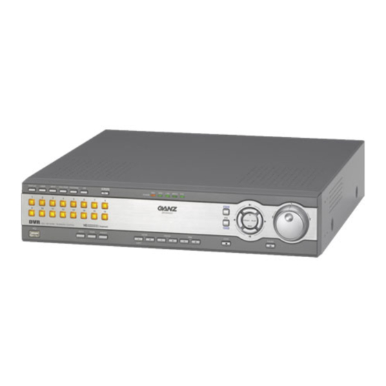
1 Parts and Features 1. 1 DVR System and Accessories Appearance may vary. ZR-DH1621NP Rack Mount Brackets RS-485/422 Terminal Block Alarm Out Terminal Block Alarm In (2EA) Terminal Block CD-ROM Power Cord RJ-11 Cable & Terminal Block... -
Page 12: Features
1. 2 Features 1) High quality digital recording Record and playback High-Resolution digital video by using Wavelet compression and decompression circuitry. 2) Simple user interface Simple operation by telemetry, integrated buttons and jog shuttle/dial. 3) High reliability Highly reliable due to a combination of hardware quality and an embedded LINUX based operating system. -
Page 13: Parts Name And Description
1. 3 Parts name and Description 1) DISPLAY Toggles between 1, 4, 9, 16, 6, 8 and 7 split screens. Enter PTZ on-screen menu in PTZ mode. 2) USER Enter user defined screen mode. Use the DISPLAY button to toggle between 4, 9, 6, 7, 10, 13, 8 and PIP screens. - Page 14 11) MENU Enter menu mode; exit sub-menus. 12) PTZ/ENTER Enter PTZ mode; select or confirm menu selection. 13) STOP Stops playback; reset alarms; hold down to select multiple cells in Recording Schedule. 14) R.PLAY, PLAY, FF, REW R.PLAY: Reverse Playback/Left PLAY: Playback/Right FF: Fast Forward/Up REW: Rewind/Down...
- Page 15 7) IEEE 1394 Connect external IEEE 1394 devices (FireWire) such as HDD and CD-RW. Notice Connect and power IEEE 1394 devices prior to powering DVR. Some devices may not be recognized when both HDD and CD-R/RW devices are present. 8) MONITOR Monitor output as composite signal.
-
Page 17: Setup And Connections
1 & PORT 2). 2. 2. 1 PORT A RS-422 There are two RJ-11 connections for PORT A which can be used to “chain” the DVR with other devices. The primary use of PORT A is to interconnect two or more DVRs and/or keypads (optional). -
Page 18: Alarm Connections
2. 3 Alarm Connections 2. 3. 1 ALARM INPUT Connect up to 16 alarm sensors using the supplied terminal blocks. 1 2 3 4 5 6 7 8 9 10 11 12 13 14 15 16 Notice Each ALARM IN should be connected with GND which is grounded by TTL or contact point. -
Page 19: External Storage
2. 5 Connecting to LAN or Internet 2. 5. 1 Making physical connection Connect the LAN port of the DVR to an available 10/100 Base-T port with a straight ethernet cable (not supplied). The link indicator LED will be lit. -
Page 21: Menu Configuration
3 Menu Configuration The features and options of the DVR are configured through the menu. • Use the Jog Dial or directional buttons to navigate through the menu. • Press ENTER button to select or confirm. • Press MENU button to return to previous menu. -
Page 22: Video Format
The recording rate and resolution can be adjusted for each recording defined in the Schedule or Manual Recording. The DVR is set to record in Schedule mode from the factory with pre-defined schedule. Thus it is always recording. To stop recording the DVR must be put into Manual Recording mode and recording turned off. - Page 23 Choose the recording methods, Field Rate and Recording Resolution for the block(s). Two settings can be specified: one for continuous recording, the other for alarm and motion recording. • Field Rate The available rate depends on the resolution and the number of channels being recorded.
-
Page 24: Specific Dates Schedule
3. 2. 2 Specific Dates Schedule In addition to the weekly schedule, up to 16 specific date/time periods can be defined. To configure the specific recording schedule select Specific Dates. • Add New Schedule With the "Add" highlighted press the ENTER button. -
Page 25: Alarm Setup
3. 3 Alarm Setup Within the Alarm Setup menu, alarm conditions and events, as well as digital motion detection settings are defined. 3. 3. 1 Alarm Outputs There are four alarm outputs. For each output, define the alarm inputs and conditions. -
Page 26: Display Setup
3. 4 Display Setup 3. 4. 1 User Defined Screen In addition to the pre-defined screens, the channels can be arranged to the user’s preference in the 8 variations of multi-screen views. This is very convenient when used with the AUTO sequencing function. Select the desired multi-screen view (1-8) using the left/right directional keys. -
Page 27: Transparency
0 ~ 80% so the images are not covered or blocked by the on-screen status or menu. 3. 5 Audio Setup The DVR can record and playback one of audio channel audio. • Gain Select the gain from 0 ~ 5. -
Page 28: Hdd Management
Specify the size (0-90%) to create the partition. • Overwrite when Disk Full Enabling this option will allow the DVR to overwrite starting with the oldest images when there is no more free storage space. When disabled the on-screen display shows the percentage of storage used. -
Page 29: Network Setup
3. 6. 3 Network Setup The DVR can be connected to a TCP/IP network to leverage the features which depend on network connection. Physically connect the DVR to the local network (LAN) using a straight ethernet cable. • DHCP DHCP is a protocol used to automatically configure the network settings of the DVR. -
Page 30: Password Administration
Select this option for automatic time synchronization to occur over the TCP/IP network using the Time Server (SNTP). • Master Select this option if the DVR will act as the time server for other DVRs on the TCP/IP network. • Use Clock Adjust Select this option for automatic time synchronization via PORT A (RS-422). -
Page 31: Firmware Management
New firmware may be available through the dealer, distributor or via the GANZ web site. It may also be readily available to the DVR over the network. 3. 6. 7 Covert Channel Covert channels are channels which are hidden, and appear to have no video input (video loss). -
Page 32: Configuration Management
• SMTP Server, Address, Port Number This setting is optional. The DVR can send e-mail directly without the use of SMTP server or MTA (message transfer agent). In certain cases all e-mail should be forwarded to a specific SMTP server. -
Page 33: System Information
• Unit ID When multiple DVRs are connected, assign an ID to each DVR. The Unit ID can be 1 ~ 255. • Unit Baud Rate Select the DVR communication speed. • PORT A, PORT 1, PORT 2 Select either DVR/keypad or one of the PTZ protocol. -
Page 34: Event Log
3. 8 Event Log The DVR keeps the log of all events it detects. The log can be filtered and displayed through the Event Log screen. Specify the start date and filter options then select Display. Some events such as alarm and motion detection can be reviewed by selecting and pressing the ENTER button. -
Page 35: Monitoring And Playback
• V.Loss indicates no video input or the channel is set as covert. 4. 2 Playback The DVR allows playback at any time even while recording. To playback the recording, press the PLAY button. To stop the playback, press the STOP button. -
Page 36: Remote Access
Remote viewing and playback is possible. The DVR can be viewed over the network with a standard web browser. On the brower address bar, type the IP address of the DVR or its DNS resolvable name. Ask a network administrator for detail. -
Page 37: Troubleshooting
No PTZ Function. Device will not enter PTZ mode. No control of PTZ camera in PTZ mode. - Check serial connections from video source to DVR No DVR response to front panel buttons. - Make sure Front Panel is not locked No External Alarm Control. - Page 38 Lost Administrator password Lost Web Access password Lost Master password Resolution - Check all audio in/out connections to DVR - Make sure audio is activated and configured - Make sure audio is associated with an active video channel - Check that new firmware version is correct - Check that USB FDD or ZIP Drive has correct file - Check network connection;...
-
Page 39: Factory Default Menu Settings
Appendix A Factory Default Menu Settings Design and specifications are subject to change without notice. Camera Setup Channel Name: no setup Brightness: 50 Contrast: 50 Saturation: 50 Hue: 0 PTZ Model: No PTZ PTZ Baud Rate: 9600 Recording Setup Schedule: Continuous for all channels Manual Recording: Continuous for all channels Record Mode: Manual... -
Page 40: Recording Rate
Appendix B Recording Rate Based on the number of video inputs and the horizontal resolution, the maximum recording rate will be adjusted automatically. As the number of channels being recorded is changed the maximum recording field/second is limited as in the table below. Lower recording rate can be selected for each channel individually. -
Page 41: Recording Time
Appendix C Recording Time The table below shows the recording time in hours based on standardized general video signal. There may be a difference depending on the contents of the video input, motion and noise level. HDD: 250GB Resolution: 720 x 240 Video: 16 Channels Audio: 8KB sampling rate 3F/1S... - Page 42 The table below shows the recording time in hours based on standardized general video signal. There may be a difference depending on the contents of the video input, motion and noise level. HDD: 250GB Resolution: 360 x 240 Video: 16 Channels Audio: 8KB sampling rate 7F/1S 3F/1S...
-
Page 43: Appendix D
Appendix D Menu Tree Main Menu Camera Setup Channel Setup PTZ Model Video Format Recording Setup Schedule Manual Recording Record Mode Alarm Setup Alarm Outputs Event Alarm Name Alarm Buzzer Display Setup User Defined Screen Sequence Spot Monitor Transparency Audio Setup Administration Language HDD Management... -
Page 44: Specifications
Appendix E Specifications VIDEO FORMAT COMPRESSION SYSTEM DVR TYPE OPERATING SYSTEM VIDEO INPUT VIDEO LOOP OUT VIDEO OUTPUT AUDIO INPUT AUDIO OUTPUT SCREEN OPTIONS RECORD MODE RECORD RATE RECORD RESOLUTION QUALITY LEVEL PRE- AND POST-ALARM ALARM PROTECTION MOTION DETECTION ALARM INPUT... - Page 45 Notes...
- Page 46 C C B B C C C C o o . . , , L L t t d d . . Tokyo. Japan www.ganz.jp P/NO: 3834RS0071X...
Need help?
Do you have a question about the ZR-DH1621NP and is the answer not in the manual?
Questions and answers