Table of Contents
Advertisement
Advertisement
Table of Contents

Related Manuals for Ganz DIGIMASTER SERIES


Summary of Contents for Ganz DIGIMASTER SERIES
-
Page 2: Table Of Contents
CONTENT OVERVIEW Before Installation Key Features Front Panel Rear Panel Remote Control At a Glance INSTALLATION HDD Installation Basic Layout Connecting to an external devices 2... -
Page 3: Before Installation
OVERVIEW Before installation Comply with the following instructions to prevent a fire, explosion, system failure or electric shock. Remove the power supply module before proceeding. Check the input voltage (AC100V–AC240V) to the power supply module before connecting it. ... -
Page 4: Key Features
OVERVIEW Key Features This product is capable of receiving inputs from up to 16 channels of 960H camera inputs of video and audio recording onto a hard disk drive in real-time, as well as providing monitoring, playback and backup footage in excellent quality of 960H resolution. It also provides transferring video and audio data to the networked external devices, which allows remote monitoring environment for computers and mobile devices including cell phones. - Page 5 OVERVIEW What's included? Mouse Remote Control Power Cable & Batteries (AAA x2) Screws Terminal Blocks User manual CD Quick Guide 5...
-
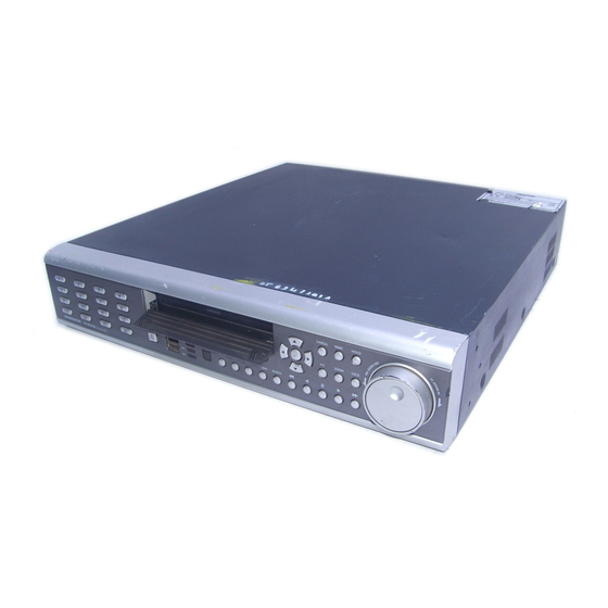
Page 6: Front Panel
OVERVIEW Front Panel Name Description IR Remote Control Receive the signal from the remote control Receiver Used for connecting USB storage or mouse. Status LED Show the status of power, recording or network connection together with the corresponding alarm. HDD 1~5 / Indicates connection status of internal/external storage HDD1 HDD2... -
Page 7: Rear Panel
OVERVIEW Rear Panel 8 channel 16 channel Name Description VIDEO IN Video input terminal for cameras. LOOP OUT Video output port to send signal to an external video device AUDIO OUT Port for speaker connection. SPOT Exclusive port for SPOT output only (Connect to a TV monitor) Power Switch DVR power switch. -
Page 8: Remote Control At A Glance
OVERVIEW Remote Control At a Glance LOGOUT POWER LOGOUT Turn on or off the power. PANIC SEARCH Start the emergency recording. Display the search window. ALARM Show the alarm status with ARCHIVE a popup window. Display the backup window. SETUP Channel Display the system setup menu. -
Page 9: Change The Remote Control Id
OVERVIEW Change the remote control ID The remote control will be active only if the remote control ID matches with that specified on the DVR. If multiple DVRs are installed on one place and you have just a single remote control, use the ID button to set the remote control ID. -
Page 10: Installation
INSTALLATION HDD Installation/Replacement 1. Remove 2 screws on both ends of DVR. 2. Pull the front side of the unit forward to separate it. 3. Hold the middle of the HDD brackets handle with index finger and pull it toward while sustaining the bracket handle with your thumb and middle finger as shown in the illustration. - Page 11 INSTALLATION 4. Once the HDD bracket is separated from the main unit, remove 4 screws on both ends of HDD bracket to separate the HDD. 5. Install a new HDD and fasten 4 screws back to both ends of the bracket to fix. ...
-
Page 12: Basic Layout
INSTALLATION Basic Layout Alarm Control Camera Device Sensor Access Controller IP Router Mouse or HUB SPOT Monitor eSATA Storage Full HD SPOT Full HD Monitor Speaker Monitor Monitor Since the cable quality may affect directly to the video quality depending on the distance between the camera and DVR, it’s recommended to consult an authorized installer when installing the DVR. -
Page 13: Connecting To An External Device
INSTALLATION Connecting to an external device Connecting to the monitor This product supports HDMI monitors and regular monitors that support VGA inputs. Once the product is set for NTSC or PAL output, connect cameras of the corresponding video standard for proper operations. Setting the product to NTSC or PAL decides available display output modes too. - Page 14 INSTALLATION Alarm I/O Connection To connect the Alarm input signal Connect the signal line of an alarm input device such as sensor to rear [ALARM IN] port Loosen screws on [IN1] through [IN16] port and [GND] port of the provided terminal block.
-
Page 15: Audio Device Connection
INSTALLATION Communication Port RS-485 Connection Connect a PTZ Camera of Keyboard Controller. After connecting the control device, be sure to match the connection settings between DVR and the device. Refer to communication settings in “Operation Manaul”. Connect three signals ([D+],[D-],[GND]) between DVR and of the control device by using provided terminal block. -
Page 16: Storage And Mouse Connection
INSTALLATION Storage and Mouse Connection External HDD USB Storage Mouse (For backup only) You can connect DVR to a PC in the same network and control or manipulate it on the PC monitor. USB Storage USB HDD USB Mouse External HDD (backup, firmware (for backup only) (for recording) -
Page 17: Network Connection
INSTALLATION Network Connection PC connection in the local network You can connect DVR to a PC in the same network and control or manipulate it on the PC monitor. Broadband Router or Hub Camera Local PC Local PC Connect the [WAN(UPLINK)] port in the rear panel to the router or hub. Connect the local PC to the router or hub. - Page 18 INSTALLATION PC connection from a remote network You can connect DVR to a PC in the same network and control or manipulate it on the PC monitor ADSL modem Remote PC Broadband Router Direct Smart Phone Connection Local PC Local PC Connect the [WAN(UPLINK)] port in the rear panel to the router.
Need help?
Do you have a question about the DIGIMASTER SERIES and is the answer not in the manual?
Questions and answers