Table of Contents
Advertisement
Quick Links
Download this manual
See also:
Operating Manual
Advertisement
Table of Contents

Related Manuals for Ganz DR-4FX1


Summary of Contents for Ganz DR-4FX1
-
Page 2: Table Of Contents
CONTENT OVERVIEW Before Installation Key Features What’s included? Front Panel Rear Panel Remote Control At a Glance INSTALLATION HDD Installation Basic Layout Connecting to an external devices 2... -
Page 3: Before Installation
OVERVIEW Before installation Comply with the following instructions to prevent a fire, explosion, system failure or electric shock. Remove the power supply module before proceeding. Check the input voltage (AC100V–AC240V) to the power supply module before connecting it. ... -
Page 4: Key Features
OVERVIEW Key Features This product is capable of receiving inputs from up to 16 channels of 960H camera inputs of video and audio recording onto a hard disk drive in real-time, as well as providing monitoring, playback and backup footage in excellent quality of 960H resolution. It also provides transferring video and audio data to the networked external devices, which allows remote monitoring environment for computers and mobile devices including cell phones. -
Page 5: What's Included
OVERVIEW What's included? Mouse Remote Control x1 Power Cable x1 & Batteries (AAA x2) DC 12V Adaptor Screws Adapter cable retainer clip x1 (For DR-8/16FX2) User manual CD Quick Guide 5... -
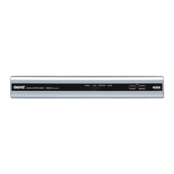
Page 6: Front Panel
OVERVIEW Front Panel DR-4FX1 Name Description IR Remote Control Receive the signal from the remote control Receiver Used for connecting USB storage or mouse. Status LED Show the status of power, recording or network connection together with the corresponding alarm. -
Page 7: Rear Panel
OVERVIEW Rear Panel 4 channel 8 channel 16 channel Name Description VIDEO IN Video input terminal for cameras. ETHERNET Network port for connection to the Internet, router or hub VGA monitor video output port. AUDIO IN 1/2 : Audio input terminal that supports channel 1 and 2. 3/4 : Audio input terminal that supports channel 3 and 4. -
Page 8: Remote Control At A Glance
OVERVIEW Remote Control At a Glance LOGOUT POWER LOGOUT Turn on or off the power. PANIC SEARCH Start the emergency recording. Display the search window. ALARM Show the alarm status with ARCHIVE a popup window. Display the backup window. SETUP Channel Display the system setup menu. -
Page 9: Change The Remote Control Id
OVERVIEW Change the remote control ID The remote control will be active only if the remote control ID matches with that specified on the DVR. If multiple DVRs are installed on one place and you have just a single remote control, use the ID button to set the remote control ID. -
Page 10: Installation
INSTALLATION HDD Installation For 4 channel model Remove the screw from the bracket on the Bottom side of the DVR. Hold the HDD bracket with your finger as shown in the figure and pull it to separate it from the DVR. Install the HDD on the bracket and fix it by fastening 4 screws on its sides. - Page 11 INSTALLATION For 8/16 channel models Remove the screw from each the bracket on the Bottom side of the DVR. Hold the HDD bracket with your finger as shown in the figure and pull it to separate it from the DVR. Install the HDD on the bracket and fix it by fastening 4 screws on its sides.
-
Page 12: Basic Layout
INSTALLATION Basic Layout Camera IP Router Monitor or HUB Full HD (RGB) SPOT Monitor Monitor Control DC 12V Device Power Speaker Sensor Alarm Since the cable quality may affect directly to the video quality depending on the distance between the camera and DVR, it’s recommended to consult an authorized installer when installing the DVR. -
Page 13: Connecting To An External Device
INSTALLATION Connecting to an external device Connecting to the monitor This product supports 1080p 60 Hz HDMI monitors and regular monitors that support DVI and VGA inputs. Once the product is set for NTSC or PAL output, connect cameras of the corresponding video standard for proper operations. - Page 14 INSTALLATION Alarm I/O Connection To connect the alarm input signal Push the Alarm In and [GND] terminals’ buttom side with a sharp tipped tool such as screw driver. While pushing, insert alarm signal cable into the hole of the Alarm In terminal. While pushing, insert ground signal cable into the the hole of the [GND] terminal.
-
Page 15: Audio Device Connection
INSTALLATION Communication Port RS-485 Connection Connect a PTZ Camera of Keyboard Controller. After connecting the control device, be sure to match the connection settings between DVR and device. Make communication settings in “Operation manual”. 1. Connect the signal cable between [D+] of the rear DVR and [D+] of the control device. 2. -
Page 16: Network Connection
INSTALLATION Network Connection PC connection in the local network You can connect DVR to a PC in the same network and control or manipulate it on the PC monitor. Broadband Router Camera Local PC Local PC Connect the [ETHERNET] port in the rear panel to the router or hub. Connect the local PC to the router or hub. - Page 17 INSTALLATION PC connection from a remote network You can connect DVR to a PC in the same network and control or manipulate it on the PC monitor ADSL modem Broadband Remote PC Router Direct Smart Phone Connection Local PC Local PC Connect the [ETHERNET] port in the rear panel to the router.
Need help?
Do you have a question about the DR-4FX1 and is the answer not in the manual?
Questions and answers