Table of Contents
Advertisement
Quick Links
Advertisement
Table of Contents

Related Manuals for Ganz Digimaster DR4HL


Summary of Contents for Ganz Digimaster DR4HL
-
Page 2: Table Of Contents
S P E C I F I C A T I O N & O R G A N I Z A T I O N - - - - - - - - - - - - - - - - - - - - - - - - - - - - - - - - - - - - - - - - - - - - - - - - - - S p e c i f i c a t i o n s - - - - - - - - - - - - - - - - - - - - - - - - - - - - - - - - - - - - - - - - - - - - - - - - - - - - - - - - - P r o d u c t C o n t e n t s L i s t... - Page 3 A l a r m O u t - - - - - - - - - - - - - - - - - - - - - - - - - - - - - - - - - - - - - - - - - - - - - - - - - - - - - - - - B u z z e r O u t - - - - - - - - - - - - - - - - - - - - - - - - - - - - - - - - - - - - - - - - - - - - - - - - - - - - - - -...
- Page 4 This manual applies to the DR4HL. This manual describes the external features of GANZ DIGIMASTER, part names, correct connection methods for supported domes or pan/tilt receivers, control devices, peripheral devices and the system setup instructions. It is important to note here that some features, figures, pictures and references can only be applied to just one model.
- Page 5 CBC reserves all copyrights of registered trademarks in this manual. Please be aware of the following precautions before installing the DVR. Avoid positioning the GANZ DIGIMASTER in any place where the unit may come into contact with moisture, dust, or soot.
- Page 6 The following are warnings and cautions to ensure user safety and prevent property damage. Please read the information below thoroughly.
-
Page 11: Important Safety Instructions
Important Safety Instructions 1) Read these instructions. 2) Keep these instructions. 3) Read all warnings. 4) Follow all instructions. 5) Do not use this apparatus near water. 6) Clean only with a dry cloth. 7) Do not block any of the ventilation openings. Install in accordance with the manufacturer's instructions. -
Page 12: S P E C I F I C A T I O N
Specifications & Organization 1. Specifications Video standard PAL/NTSC Audio 2-way Audio conference Monitor display Real time:25 Fps (PAL), 30Fps(NTSC) per camera Covert camera operation Programmable Event/Log search limitation user login/out, config changes, remote access, connects/disconnects Record Scheduling Daily, Weekly adjust specific Hr per channel Remote Access TCP/IP, View, Search, Recording &... -
Page 13: P R O D U C T C O N T E N T S L I S
Product Contents List Please check if all the product contents are present after opening the package. DR4HL 12V Adaptor (With cord) Remote Agent Instruction Manual Remote Controller Mouse Installation CD (With Battery) System Organization... -
Page 14: P R O D U C T D E S C R I P T I O
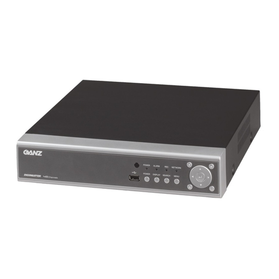
Product Description 1. Front Panel - USB PORT: Port for USB devices, for mouse and backup. - POWER: Turn on power of system. - DISPLAY: Select display mode between split and full mode. - SEARCH: Enter to search menu - MENU: Enter to system configuration menu. - NAVIGATION KEY: use for navigating on menu or control PTZ. -
Page 15: Manual Recording
SYSTEM CONFIGURE – Remote Controller SYSTEM SETUP POWER BUTTON MANUAL RECORDING ENTER NAVIGATION RETURN MENU DISPLAY KEYLOCK SEQUENCE ARCHIVE CONNECT & POWER ON • Connect up to 4 CAMERA INPUTS as necessary. • Connect one or more monitors to the DVR using the COMPOSITE, VGA connections •... -
Page 16: L I V E D I S P L A
After startup diagnostics are complete, the operator must logon to the system. The default user name is ‘ADMIN’. the default password of ‘1234’ and press the ENTER button. Double click on the Password tap then the Virtual Keyboard will be appeared. Then, click the password and click the OK button. -
Page 17: M A N U A L R E C O R D I N
Click the right mouse button on the Live Display screen and click the SEQUENCE menu. All the display modes are static with the exception of the sequence mode. In this mode, the sequence symbol ( ) is displayed and each channel is shown in full screen for a set period of time before switching to the next channel. -
Page 18: K E Y L O C K F U N C T I O
Key Lock Function Click the right mouse button on the Live Display screen and click the LOGOFF menu. An operator with ADMIN rights can choose to lock the DVR with mouse menu. Select the KEYLOCK button and YES. PTZ Camera Control Click the right mouse button on the Live Display screen and click the PTZ menu. -
Page 19: S Y S T E M S E T U
Click the PRESET & SWING menu. All menus can be controlled by navigation key and pressing the mouse click. SYSTEM SETUP Click the right mouse button on the Live Display screen and click the SETUP menu. DISPLAY : To setup the various display options, highlight DISPLAY and press ENTER. DISPLAY - OSD Click the OSD menu and click the ON/OFF menu. -
Page 20: Monitor
STATUS BAR : Turns the status bar at the bottom of the live display ON or OFF. CAMERA TITLE : Determines whether the camera title is displayed. EVENT ICON : Determines whether the DVR recording status is shown at the top right of each channel display window. -
Page 21: C A M E R
CAMERA To setup the various camera options, highlight CAMERA and press ENTER. CAMERA : CAMERA TITLE Click the CAMERA TITLE menu and click ON/OFF menu on the COVERT menu. Then, click the button for ON/OFF. Click the CAM No on the TITLE menu and change the camera name. - Page 22 Click the each value by button. The selected channel is displayed in full screen. BRIGHTNESS, CONTRAST, TINT and COLOUR can be changed as necessary. To modify a different channel, highlight CAMERA and choose the desired channel. Press RETURN when all changes are completed. DISPLAY : PTZ SETUP Click the PTZ SETUP menu and click the each value the ADDRESS, PROTOCOL and BAUD RATE menu.
- Page 23 value by button. PTZ properties can also be adjusted for each channel by selecting the icon and pressing ENTER. Note that some settings, such as AUTO FOCUS, may not be compatible with particular PTZ equipment. If this is the case, changing this value will have no effect on PTZ control. DISPLAY : MOTION SENSOR Click the MOTION SENSOR menu and decide the value the SENSITIVITY menu.
-
Page 24: Camera Mode
The area on the picture shows that motion will be detected across the entire image. To quickly select or deselect the entire grid, click the right mouse button and click SELECT ALL or DESELECT ALL menu. Or press RETURN to bring up the motion menu to select or deselect the entire grid,. Choose SELECT ALL or DESELECT ALL as appropriate. -
Page 25: S O U N
To use LINELOCK CAMERA, set to ON a LINELOCK CAMERA MODE. SOUND To setup the various sound options, highlight SOUND and press ENTER. SOUND : AUDIO Click the AUDIO menu and click the ON/OFF menu. Then, click the button for ON/OFF. LIVE AUDIO : When it is set to ON, the selected audio channel can be monitored on the AUDIO OUTPUT. -
Page 26: System
REMOTE CONTROL: When set to ON, each command received from the IR remote, is confirmed by a beep. SYSTEM To setup the various system options, highlight SYSTEM and press ENTER. DATE / TIME Click the DATE / TIME menu and click the ON/OFF menu. Then, click the button for ON/OFF. -
Page 27: Network
SYSTEM : NETWORK Press the NETWORK menu and click the ON/OFF menu. Then, click the button for ON/OFF. DHCP : When enabled, the DVR will obtain an IP address automatically if connected to a DHCP server or router. DDNS : When enabled, the DVR can be accessed through a Dynamic DNS server. Commonly used if a broadband connection does not have a static IP address. -
Page 28: Mail
SYSTEM : MAIL Press the MAIL menu and click ON/OFF menu. Then, click the button for ON/OFF. SERVER : The SMTP outbound email server that should be used to send email notifications. PORT : The outbound email port number. SECURITY : Set to OFF if the SERVER does not require a username and password to connect. USER : Enter a username to identify the DVR in email messages. - Page 29 By default, the DVR is configured with a user ID of ADMIN, belonging to the ADMIN group and with a password of 1234. As well as the ability to add new users, existing user details can be modified. To modify user details, highlight the user with the blue box and double click. Double click the ADD button.
- Page 30 By virtual keyboard, detailed information can be changed. SYSTEM: SYSTEM MANAGEMENT Click the SYSTEM MANAGEMENT menu. SYSTEM INFORMATION - IP ADDRESS: Shows either the manual IP address entered in NETWORK setup or the IP address assigned by a DHCP server if enabled. - MAC ADDRESS: Shows the MAC (Media Access Control) address of the DVR.
- Page 31 channel 1 input signal at power on. - DDNS SERVER : If DDNS is enabled, the host DDNS server is specified here. - RTSP SERVER PORT : The port number that the DVR uses to support remote connection from the client software.
- Page 32 4) After finishing, system is rebooted. 5) After rebooting one time, system will ask to reboot again with below pop-up window. Press “OK” and system reboot again. After finishing reboot, F/W upgrade is finished successfully. FACTORY DEFAULT: If settings have been changed which cause erratic behavior, the factory default settings can be loaded.
-
Page 33: Control Device
Caution: If you try to factory default, system will ask to format after finishing the factory default. SYSTEM DATA : System settings can be saved to a USB memory stick. The settings can be reloaded in case of accidental factory reset or can be transferred to another DVR if multiple units need to be installed with the same settings. -
Page 34: Event / Sensor
PROTOCOL: Must be set by Control Device. BAUD RATE: Must be set to match the baud rate of the PTZ controller. EVENT / SENSOR To setup the various event handling options, highlight EVENT/SENSOR and press ENTER EVENT / SENSOR: HDD EVENT Click the HDD EVENT menu. -
Page 35: H D D E V E N
Determine the behavior of each of the 4 alarm inputs. OPERATION: Alarm inputs can be enabled or disabled. TYPE: Alarm inputs can be set as normally open (N/O) or normally closed (N/C). EVENT / SENSOR: ALARM OUTPUT Click the ALARM OUTPUT menu and click each value. - Page 36 Click the BUZZER OUTPUT menu and click each value. Then, click the value by button to change. Determine the behavior and actions that will trigger the internal buzzer. Behavior settings OPERATION : The internal buzzer can be enabled or disabled. HDD EVENT : Determines whether a hard drive event sounds the buzzer.
-
Page 37: D I S K M A N A G
NOTIFICATION : Email notification can be turned ON or OFF. HDD EVENT : Determine whether a hard drive event sends an email. BOOTING EVENT: Determines whether a reboot event sends an email. Action settings ALARM : Determine whether alarm inputs will send an email. VIDEO LOSS: Determine whether video loss on any of the selected channels will send an email. -
Page 38: R E C O R D M E N
DISK INFORMATION: Checking HDD Information. Please note: When a RECORD TIME LIMIT is set, the OVERWRITE option cannot be changed RECORD MENU Click the RECORD SETUP menu. To setup the recording behavior of the DVR, highlight RECORD MENU and press ENTER. RECORD : RECORDING OPERATIONS Click the RECORDING OPERATION menu and click the each value. -
Page 39: S I M P L E R E C O R D I N
SCHEDULE MODE : Either DAILY (one schedule will apply to every day of the week) or WEEKLY (each day of the week has its own schedule). Please note: When recording mode is simple mode, this option cannot be changed. PRE EVENT RECORDING TIME : When the DVR is not in continuous recording mode, this setting determines the amount of footage that is always recorded before an event occurs. -
Page 40: A D V A N C E D R E C O R D I N
Click a single block to open the recording type menu. Click and Drag a block of times to configure multiple channels and times at once. ADVANCED RECORDING Click the ADVANCED RECORDING menu. This setup screen allows the operator to configure the recording mode of continuous, motion and alarm recording. There are 2 sections: SETTING: Recording settings for each channel can be defined across a 24 hour period, in blocks (for example between 09:00 and 18:00) or for each individual hour. - Page 41 Select the time block that want to set. Click the SIZE, FPS, QUALITY, AUDIO and ALARM value. Then, click the value by button to change. Press ENTER. Recording settings for the selected time period are displayed. SIZE : Recording resolutions of 352x240/352x288, 704x240/704x288 or 704x480/704x576 can be selected for each channel.
-
Page 42: M A N U A L R E C O R D I N
Remember that if SCHEDULE MODE is set to WEEKLY, recording settings need to be changed by each day as well as each particular time Note: The DVR supports a maximum recording rate across all channels of 120 frames per second at 352x240 resolutions. -
Page 43: S E A R C
Click the MANUAL RECORDING. Select the Size, Frame, Quality and audio. During manual recording mode, the DVR will override all other recording settings and record continuously on all channels at the settings configured here. Manual recording time: After passing the assigned time, recording is returned as original recording type. SEARCH Click the right mouse button on the Live Display screen and click the SEARCH menu. - Page 44 The DVR uses a calendar and timeline search method for quick access to recorded footage. The calendar displayed on the left shows the current month. Days highlighted in green have recorded footage. The timeline on the right shows a 24 hour status of all channels for the selected day. Light blue areas show recorded footage.
- Page 45 Playback speed and direction can be controlled using the five playback buttons in menu. To exit the search screen and go back to live view, repeatedly press RETURN. SEARCH : EVENT SEARCH The DVR event log stores events such as motion and alarm activated recording, video loss etc. Click the SEARCH BY EVENT menu and each value.
-
Page 46: A R C H I V I N
Highlight START and press ENTER to display the event log for the criteria selected. To playback footage for a particular event, select the event from the list using the CURSOR KEYS and press ENTER. Playback resumes from the moment the selected event occurred and continues until stopped by the operator. During event search playback, playback buttons can be used as normal. - Page 47 Click the right mouse button on the Live Display screen and Click the ARCHIVING menu. To archive recorded footage to USB memory stick , select the ARCHIVING button. To protect unauthorized viewing and distribution of footage, only the ADMIN user level can archive footage. To login as ADMIN, enter the default password of 1234 and press ENTER.
- Page 48 SELECT DEVICE: Choose between USB device. MODE: ‘Bruning’ or ‘Erasing&Burning’ Please note: To use a USB memory stick, it must be inserted before selecting the archiving menu Additionally make sure to do the “PREVIRW” firstly. If not doing the “PREVIEW”, user can not start backup.
-
Page 49: R E M O T E C L I E N T S E T U
REMOTE CLIENT SETUP PRELIMINARY BEFORE CONNECT For using web connection, 554 and 8080 ports should be done port forwarding set in Router. Refer the manual of Router for port forwarding setting WEB RA MINIMUM PC REQUIREMENT P4 3.0 or Higher 512MB or Higher Geforce MS 400, Radeon 7500 or higher... - Page 50 http://1234.dvrlink.net (webport :80) Default ID and password are ‘ADMIN’ &’1234’ User needs to install Active-X, click Run Add-on In case of, unable to install active-X, User needs to check the option of activeX on IE security menu.
-
Page 51: L I V E M O D
Select Enable for all ActiveX related options. (ex, Download signed ActiveX control, Download unsigned ActiveX control….) 12.2 LIVE MODE Explanation of function button in LIVE mode... - Page 52 Select live division screen. Move to next screen and make full screen Select live channel. Activate Mic to send a sound to DVR. On/Off Sound from DVR Save the live image. Print the current screen. Snapshot the current screen. Setup [Render] and [Save Folder] Status : Can see the current DVR status.
-
Page 53: Camera.
Log : Can see the log. PTZ : Can control connected PTZ camera. Pattern – move a camera among several preset position Preset – set a position of camera view. Swing – move a camera between two preset point. 12.3 SEARCH (Common time line search) -
Page 54: S E A R C
Select a time line on time table or set a exact time. Then press ‘Play’ button 1. Refresh : Refresh the data. 2. Play : After select the date and time, can play the data. 3. Backup : Can backup special channel and time. 12.4 SEARCH BY EVENT 1. -
Page 55: S E T U P M O D
Select a event on the list then DVR starting to playback the related camera’s image 12.5 SETUP MODE All settings are same as DVR setup. CAMERMA user can configure camera’s attribute such as title, live color, PTZ setup or motion Motion setup for detecting motion events. -
Page 56: Display
Display 1) OSD – User allow to choose text display items over the image. 2) Monitor - user can set dwell time for sequence or spot, and pop up function. Sound 1) Audio Setting – Select a live audio channel and activation 2) Buzzer setting –... -
Page 57: U S E
User Allow to add user, select Authority level and Log out time Network User can check the system’s network information and selectable speed level. But IP settings are not allowed to change on remote site. Network IP only can set on system. For email notification, user can input the SMTP server detail on below setup. -
Page 58: 12.6 Information
12.6 INFORMATION Check DVR model name and WEB version. 13 SMART PHONE CONNECTIONS ♣ I-PHONE 1. Select the Safari browser 2. Enter the IP address or URL to connect. And Click the [GO] button. 3. Enter the User name and Password then use can see the Image. (Default ADMIN / 1234) Only allow to surveillance live view, not playback and other function. -
Page 59: B L A C K B E R R
♣ Blackberry 1. Select the Web browser. Enter the IP address or URL to connect. And press the Enter button. 3. Enter the User name and Password then use can see the Image. (Default ADMIN / 1234) The DVR is supplied with software to allow remote connections either on a direct LAN connection or over the Internet.
Need help?
Do you have a question about the Digimaster DR4HL and is the answer not in the manual?
Questions and answers