Advertisement
Table of Contents
- 1 Table of Contents
- 2 System Installation Planning
- 3 Device Introduction
- 4 Remote Controller
- 5 First Time Setup
- 6 Mount Devices
- 7 System Default Setting
- 8 User Menu
- 9 Programming Mode
- 10 Operation
- 11 Tamper Protection
- 12 Connect2Home Application
- 13 Troubleshooting & Factory Reset
- 14 Specifications
- Download this manual
Advertisement
Table of Contents

Related Manuals for Blaupunkt SA 2700


Summary of Contents for Blaupunkt SA 2700
- Page 1 SA 2700 Kit User Manual...
-
Page 2: Table Of Contents
9. Connect2Home Application ____________________________________________ 26 10. Troubleshooting & Factory Reset ______________________________________ 27 11. Specifications ______________________________________________________ 29 Information and illustrations are subject to change within this document. Blaupunkt reserves the right to alter the specification and product design at anytime without notice. -
Page 4: System Installation Planning
Detector for fire protection; Temperature Sensor for High/Low Temperature report; and Power Switch energy management Home Automation. Please check Blaupunkt website http://www.blaupunkt.com/us/products/home-security/ to learn more about accessory devices. For more information, please see 7. Programming Mode – Device +/- General Device Location Guideline: ... - Page 5 Device Location Panning: Door Contact The Door Contact should be mounted as high as possible. Do not aim a PIR sensor at this door/window. Remote Controller It is used inside or outside your home and can be kept on the key ring PIR Sensor ...
-
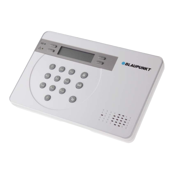
Page 6: Device Introduction
NOTE: The kit package you purchased includes the following devices: 1 x PIR Sensor, 1 x Door Contact, 1 Remote Controller For other useful devices, see http://www.blaupunkt.com/us/products/home-security/ Control Panel Tamper Down... - Page 7 PIR Sensor The PIR sensor detects movement and raise alarm when it detects an intruder. The PIR sensor is powered by 2 1.5V AA alkaline batteries pre-inserted by factory. Pull out the plastic battery saver tab on the back of PIR sensor, this will activate the batteries. The LED will flash for 30 seconds to indicated the PIR is warming up ...
-
Page 8: Remote Controller
Remote Controller You can arm, home, disarm, and activate an Emergency alarm with your Remote Controller For disarming action, you can only use Remote Controller to disarm the system after you have triggered an entry Door Contact or PIR sensor. ... -
Page 9: First Time Setup
3. First Time Setup This quick guide will take you through a step by step process of system initial setup. NOTE: The First Time Setup process is only availble when you power on the Control Panel for the first time. Once the process is completed, it will not appear again. All of the options can be changed later again, do not worry if you make any mistakes. - Page 10 Press OK to continue, enter a 4-digit PIN code. Press OK to confirm. E x i t S e t u p R e p e a t S e t u p If you are satisfied with current setting, select Exit Setup and press OK to confirm. If you want to make changes to current setting, select Repeat Setup and press OK to confirm.
-
Page 11: Mount Devices
4. Mount Devices This chapter will guide you through device mounting process. After you complete First Time Setup process, if the Control Panel has already included accessory devices, the screen should display: M o u n t D e v i c e s s e e m a n u a l Proceed to mount your sensors and accessory devices, tamper alarm will be disabled while the... - Page 12 3. Hook the Control Panel onto the plate, then slide the control panel left to secure the panel and depress the tamper switch against the mounting plate. (Figures 4) Figures 4 PIR Sensor The PIR Sensor has knockouts on the back where plastic is thinner. The 2 central knockouts are for flat wall mounting, and the four side knockouts are for corner mounting.
- Page 13 Door Contact The Door Contact has two knockouts on the inside of the back cover where plastic is thinner for wall mounting. (Figure 1) The Door Contact should be mounted on the door/window frame, while the magnet should be mounted on the door/window. 1.
-
Page 14: System Default Setting
5. System Default Setting Entry/Exit Time and Device Attribute When the system is armed and an Entry device is triggered, the Entry timer will begin to count down (default 20 seconds). The system must be disarmed before the timer expires, or a Burglar alarm will be activated. -
Page 15: User Menu
6. User Menu The User Menu displays the system basic information and allows you to test system function Entering User Menu When the system is in Disarmed Mode (Alarm off), enter your User PIN Code to access User Menu. Press a numeric key or , the display will prompt you to enter the PIN code: E n t e r C o d e... - Page 16 Walk Test Walk Test allows you to test the signal range of sensor and accessory devices. To test the device 1. Press the test or learn button on the device, refer to device user manual for detail. 2. If the Control Panel receives the signal, the screen will display device type, zone number, attribute, name signal strength in 0~9 scale accordingly.
-
Page 17: Programming Mode
7. Programming Mode To access the Programming Mode, you need to first enter the User Menu, and select P-Mode under User Menu. The screen will prompt you to enter the Master Code. P - M o d e E n t e r M - C o d e . - Page 18 4. Select the report type for this telephone number, there are 2 choices: Voice Report – The Control Panel will dial the telephone number and play pre-recorded voice message according to the event upon answer. Telephone number set to Voice Report will be marked with “V” in the telephone number menu. SMS Report –...
- Page 19 General Setting Program your system general setting under this menu. The items available include the following – see a) to g): a) PIN Code The PIN code is used to access the User Menu, and Arm/Home/Disarm the system. The system can store up to 4 User PIN Codes, each PIN code consists of 4 digits.
- Page 20 e) Door Chime This function allows you to decide whether the Control Panel should emit a two-tone Door Chime sound to notify the user when a Door Contact or PIR Detector set to Entry is triggered under Disarmed mode. Options available are : High, Low, Off ...
- Page 21 logged, reported to programmed telephone number and displayed on the LCD to warn the user. Detection Off is set as factory default. e) Final Door If set to On, when the system is being Away Armed and a Door Contact set to Entry attribute is closed before the Exit Delay timer expires, the system will enter Away Arm mode immediately even if the Exit Delay timer has not expired yet.
- Page 22 Device +/- Devices +/- allows you to add/remove /edit devices. The functions include: Add Devices Edit Devices Remove Devices Learn PSS Add Devices 1. To learn in a device, select Add Device, press “OK” to confirm. 2. Press the test /learn button on the device, refer to device manual for detail. 3.
- Page 23 Remote Controller --- RC Remote Keypad ---KP Smoke Detector --- SD Temperature Sensor --- TS Outdoor Siren --- BX Edit Devices Use Edit Device to change setting for learned in devices. The screen will display available devices. 1.
- Page 24 Reset GSM Reset GSM function allows you to reset your GSM module. You can reset the GSM if the Panel has GSM related fault conditions to try to solve the problem. 1. When you select the function, the screen will display “Please wait”. Do not touch the Control Panel during the GSM reset process 2.
-
Page 25: Operation
8. Operation This chapter covers system general characteristic under normal operation. Away Arm Away Arm will arm all devices in the system Arming the System When the system is under Disarm mode: 1. Press the “Arm” key on the Control Panel, Remote Controller, or Remote Keypad. 2. - Page 26 Force Arm When you arm the system, if any fault event exists, the Control Panel will sound a ding-dong warning sound to indicate arming is prohibited, the fault event will be displayed on screen. At this moment, you can first rectify all of the problems and then clear the Fault Display and you will be able to arm the system normally.
-
Page 27: Tamper Protection
Stopping the Alarm Enter a User PIN Code and press OK key on the Control Panel. Enter a User PIN Code and press Disarm key on the Remote Keypad. Press Disarm key on the Remote Controller The alarm will be stopped;... - Page 28 If more than one number is programmed the Control Panel will continue to dial the number(s) until a recipient presses the third response key. If no phone number is programmed, the Control Panel will not dial. Call Acknowledgement When the Control Panel makes Voice Report, there are 3 responses available for the recipient to receive the call, by pressing 1, 0 or 9 key on his telephone set.
-
Page 29: Connect2Home Application
For Android user, Android 2.2 or higher version is required. How do I use the “Connect2Home” application? Once you have downloaded and installed the app on your smartphone, please visit Blaupunkt website www.blaupunkt.com to download the user guide for Connect2Home application. -
Page 30: Troubleshooting & Factory Reset
10. Troubleshooting & Factory Reset This chapter covers the potential issues you may encounter during system operation, and factory reset function Control Panel Control Panel Fault Orange LED indicates fault in system, When the LED light up, please enter User Menu and select Fault Dsp to view fault events. The possible fault events include: ... - Page 31 PIR is slow to respond: -- This is normal. PIR has sophisticated false arm filter setting to prevent accidental trigger. It is also less sensitive when walking directly toward it: PIR give false alarm: -- Make sure pets have no access to protected area. -- Make sure the PIR is not pointed at source of heat or moving objects Door Contact ...
-
Page 32: Specifications
11. Specifications All Devices Environmental Condition -10°C to 40°C, relative humidity 85% non-condensing for Control Panel and all devices. Radio Operation Range About 30m in typical domestic installation, range can vary depending on building construction, device location, and environment. Control Panel Display 2x16 character LCD Keypad... - Page 33 To assure continued compliance, any changes or modifications not expressly approved by the party responsible for compliance may void the user's authority to operate this equipment. (Example - use only shielded interface cables when connecting to computer or peripheral devices). Blaupunkt Competence Center Security & Care Azure Security & Care Corporation www.blaupunkt.com 6F., No.1, Lane 250, Sinhu 2nd Rd.,...
Need help?
Do you have a question about the SA 2700 and is the answer not in the manual?
Questions and answers