
Related Manuals for Extron electronics FOX Matrix 3200


Summary of Contents for Extron electronics FOX Matrix 3200
- Page 1 User Guide Fiber Optic Matrix Switchers FOX Matrix 3200, FOX Matrix 7200 Configurable Fiber Optic Digital Matrix Switchers 68-1740-02 Rev. A 03 14...
-
Page 2: Safety Instructions
Safety Instructions Safety Instructions • English Инструкция по технике безопасности • Русский WARNING: This symbol, , when used on the product, is intended to ПРЕДУПРЕЖДЕНИЕ: Данный символ, , если указан alert the user of the presence of uninsulated dangerous voltage within the на... - Page 3 FCC Class A Notice This equipment has been tested and found to comply with the limits for a Class A digital device, pursuant to part 15 of the FCC rules. The Class A limits provide reasonable protection against harmful interference when the equipment is operated in a commercial environment. This equipment generates, uses, and can radiate radio frequency energy and, if not installed and used in accordance with the instruction manual, may cause harmful interference to radio communications.
- Page 4 FDA/IEC 60825-1 Requirements CLASS 1 LASER PRODUCT Complies with FDA performance standards for laser products except for deviations pursuant to Laser Notice No. 5, dated June 24, 2007. The product is intended to be used with the fiber optic cables fully installed. This product meets the applicable requirements of IEC 60825‑1, Edition 1 (2007).
- Page 5 Conventions Used in this Guide Notifications The following notifications are used: WARNING: A warning indicates a situation that has the potential to result in death or severe injury. ATTENTION: Attention indicates a situation that may damage or destroy the product or associated equipment.
-
Page 7: Table Of Contents
Power ............26 Creating a Configuration ....... 26 Viewing the Configuration ......31 I/O Grouping ..........33 Using Presets ..........37 Muting and Unmuting Outputs ...... 39 Locking the Front Panel (Executive Mode)..41 FOX Matrix 3200 and 7200 Switchers • Contents... - Page 8 Gateways ........... 122 Local and Remote Devices ......122 IP Addresses and Octets ......122 Subnet Masks and Octets ......122 Determining Whether Devices Are on the Same Subnet ........123 FOX Matrix 3200 and 7200 Switchers • Contents viii...
-
Page 9: Introduction
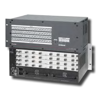
FOX Matrix 3200 Switcher and FOX Matrix 7200 Switcher. These customizable matrix switchers support up to 32 (FOX Matrix 3200) or 72 (FOX Matrix 7200) inputs and outputs. NOTE: In this guide, “FOX matrix switcher” and “switcher” refer to either switcher model unless otherwise specified. - Page 10 By adding or removing I/O boards, the FOX matrix switcher is expandable and contractable within the following ranges: • FOX Matrix 3200 — Includes up to four I/O boards. It is expandable from an 8‑input by 8‑output matrix to a 32‑input by 32‑output matrix. •...
- Page 11 The matrix switcher is housed in a rack‑mountable, metal enclosure with mounting flanges for standard 19‑inch racks. The sizes are as follows: FOX Matrix 7200 — 8U high • • FOX Matrix 3200 — 4U high FOX Matrix 3200 and 7200 Switchers • Introduction...
-
Page 12: Fiber Cable Transmission Modes
Windows‑based control program on a local‑area network (LAN) or Internet (IP) connection. Rooming — The switcher can be programmed to group multiple outputs to specific “rooms”, allowing them to have their own presets. FOX Matrix 3200 and 7200 Switchers • Introduction... - Page 13 Front panel controller • Windows‑based Matrix Switchers Control Program • Simple Instruction Set (SIS) • Remote control panels and keypads • FOX Matrix 3200 and 7200 Switchers • Introduction...
- Page 14 Global memory presets — 32 (FOX Matrix 3200) or 64 (FOX Matrix 7200) global memory presets are a time‑saving feature that lets you set up and store input/output configurations in advance.
-
Page 15: Installation
17] and a LAN port [page page 13]). Connect power (page 16). … Test the switcher by creating a tie (page 27). … Ancillary Operations Install the Matrix Switchers Control Program (page 72). … FOX Matrix 3200 and 7200 Switchers • Installation... -
Page 16: Rear Panel Boards, Cabling, And Features
50/60Hz 1.2A MAX. REFERENCE REFERENCE Figure 3. FOX Matrix 3200 Fiber Optic Matrix Switcher Rear Panel ATTENTION: • Use electrostatic discharge (ESD) precautions (be electrically grounded) when you make connections. ESD is damaging, even if you cannot feel, see, or hear it. - Page 17 Reset button (see page Switch Reference connectors (see page Power connectors (see page Power supply modules and indicator LEDs (see page Cooling fan assembly (see Removing and Installing a Fan Module on page 114) FOX Matrix 3200 and 7200 Switchers • Installation...
-
Page 18: I/O Boards
On the SDI/HD‑SDI I/O boards, inputs and outputs are grouped separately, with inputs A through H on the left and outputs A through H on the right. FOX Matrix 3200 and 7200 Switchers • Installation... - Page 19 Extron cable to the Optical 2 connector on a receiver. Fiber Optic Receiver OPTICAL Input LED — See Fiber optic I/O board LED on the next page. indications Figure 7. Optical Connections FOX Matrix 3200 and 7200 Switchers • Installation...
- Page 20 9) — Ç Multi-rate SDI Input connectors — Connect HD‑SDI, SDI, or 3G‑SDI video inputs to these BNC connectors. É Multi-rate SDI Output connectors — Connect digital displays to these BNC connectors. FOX Matrix 3200 and 7200 Switchers • Installation...
-
Page 21: Remote Port
Ethernet cables are limited to a length of 328 feet (100 meters). NOTES: • Do not use standard telephone cables. Telephone cables do not support Ethernet or Fast Ethernet. • Do not stretch or bend cables. Transmission errors can occur. FOX Matrix 3200 and 7200 Switchers • Installation... -
Page 22: Reset Button And Led
NOTES: • Factory loaded firmware is active until it is replaced or the power is cycled. • Hard reset does not clear the current configuration. FOX Matrix 3200 and 7200 Switchers • Installation... -
Page 23: Switch Reference Connections
Ties to any output in I/O group 2 use the bi‑level sync reference. I/O grouping on page 33 to assign sync‑critical inputs and outputs to the appropriate I/O groups. If no external sync timing source is connected to the switcher, switching occurs immediately. FOX Matrix 3200 and 7200 Switchers • Installation... -
Page 24: Power Supply Modules And Indicator Leds
SDI/HD-SDI Video Camera Video Camera Video Camera Figure 12. Multiple Device Example of a FOX Matrix 3200 External Sync Power Supply Modules and Indicator LEDs Primary and Redundant AC power connectors (see figure 3 on page 8 and figure 4 on page 9) —... -
Page 25: Front Panel Configuration Port
RS‑232 up to 250 feet (76 meters) away. This port is RS‑232 only, with its default protocols as follows: • 9600 baud • no parity • 8 data bits 1 stop bit • no flow control • FOX Matrix 3200 and 7200 Switchers • Installation... -
Page 26: Operation
Output buttons (see page 21). Enter button (see page 22). Preset button (see page 22). View button (see page 23). Esc button (see page 23). Primary and Redundant Power Supply LEDs (see page 23). FOX Matrix 3200 and 7200 Switchers • Operation... - Page 27 Output buttons (see page 21). Enter button (see page 22). Preset button (see page 22). View button (see page 23). Esc button (see page 23). Primary and Redundant Power Supply LEDs (see page 23). FOX Matrix 3200 and 7200 Switchers • Operation...
-
Page 28: Input And Output Buttons
Assign an input to the selected group in I/O Group mode and indicate its assignment. Select a preset. • • (Input 1 and Input 2 only) Toggle background illumination of the buttons on and off. FOX Matrix 3200 and 7200 Switchers • Operation... - Page 29 Select a preset. • • Mute the output. Output 31 (FOX Matrix 3200) or Output 71 (FOX Matrix 7200) — Select • the RS‑232 protocol for the RS‑232/RS‑422 port in Serial Port Selection and Configuration mode and indicate its selection.
-
Page 30: Control Buttons
With the Enter, View, and Esc buttons, selects Serial Port Selection and Configuration mode. • Selects 19200 baud for the rear panel Remote port in Serial Port Selection and Configuration mode and indicates the selection. FOX Matrix 3200 and 7200 Switchers • Operation... -
Page 31: Power Indicators
Red — Indicates that the associated power supply is operating outside the normal tolerances or has failed. See Removing and Installing the Power Supply Module on page 113 to replace the power supply. FOX Matrix 3200 and 7200 Switchers • Operation... -
Page 32: Button Icons
Red — Indicates that the associated power supply is operating outside the normal tolerances or has failed. See Removing and Installing the Power Supply Module on page 113 to replace the power supply. FOX Matrix 3200 and 7200 Switchers • Operation... -
Page 33: Front Panel Operations
Current configuration — The configuration that is currently being used (also called configuration 0). Global memory preset — A configuration that has been stored. The FOX Matrix 3200 can store up to 32 global memory presets in memory and the FOX Matrix 7200 can store up to 64 presets. -
Page 34: Power
An optical input can be tied to one or more of both the optical and SDI/HD‑SDI outputs, and an SDI/HD‑SDI input can be tied to one or more of both the SDI/HD‑SDI and optical outputs. FOX Matrix 3200 and 7200 Switchers • Operation... - Page 35 Confirm the change: Press and release the Enter button. Press the Enter button to confirm the configuration change. All input buttons and output buttons ENTER return to unlit or background illumination. The Enter button returns to unlit or background illumination. FOX Matrix 3200 and 7200 Switchers • Operation...
- Page 36 C O N T R O L 8 15 16 VIEW ENTER PRESET 17 18 19 20 21 22 23 24 31 32 The Enter button blinks to indicate the need to OUTPUTS confirm the change. FOX Matrix 3200 and 7200 Switchers • Operation...
- Page 37 The Output 1, Outout 3, Output 4, and Output 8 buttons light to indicate the ties created in example 1 and example 2. 8 15 16 17 18 19 20 21 22 23 24 31 32 OUTPUTS FOX Matrix 3200 and 7200 Switchers • Operation...
- Page 38 The current configuration (see figure 21) is now input 5 video is tied to output 1, output 3, and output 8. Input 5 video tied to outputs 1, 3, and 8 Input Output Figure 21. Final Configuration, Example 3 FOX Matrix 3200 and 7200 Switchers • Operation...
-
Page 39: Viewing The Configuration
ENTER PRESET VIEW The button lights. Until you select an input, only the buttons for untied outputs light. 8 15 16 17 18 19 20 21 22 23 24 31 32 OUTPUTS FOX Matrix 3200 and 7200 Switchers • Operation... - Page 40 Exit View-only mode: Press and release the View button Press the View button to exit View-Only mode. All input buttons and output buttons VIEW return to unlit or background illumination. The View button returns to unlit or background illumination. FOX Matrix 3200 and 7200 Switchers • Operation...
-
Page 41: I/O Grouping
2. Ungrouped inputs and outputs can be switched to outputs and inputs in any group. Ties between groups (an input in group 1 tied to an output in group 2) can be created under RS‑232/RS‑422 or Ethernet control. FOX Matrix 3200 and 7200 Switchers • Operation... - Page 42 • For I/O groups to have any function, at least two groups must be created. FOX Matrix 3200 and 7200 Switchers • Operation...
- Page 43 One at a time, press and release the Output 1 through Output 4 buttons. The selected buttons light. 8 15 16 17 18 19 20 21 22 23 24 31 32 OUTPUTS FOX Matrix 3200 and 7200 Switchers • Operation...
- Page 44 Do nothing for approximately 30 seconds. The switcher exits I/O Group mode. In this example: • Group 1 consists of inputs 1 through 4 and outputs 1 through 4. Group 2 consists of inputs 5 through 8 and outputs 5 through 8. • FOX Matrix 3200 and 7200 Switchers • Operation...
-
Page 45: Using Presets
The current configuration (configuration 0) can be saved as a preset in any one of 32 (FOX Matrix 3200) or 64 (FOX Matrix 7200) preset memory addresses. Presets can be saved and recalled from the front panel. The preset locations are assigned to input buttons 1 through 32 (64). - Page 46 C O N T R O L ENTER PRESET VIEW All input buttons and output buttons return to unlit or The Enter and Preset background illumination. buttons return to unlit or background illumination. FOX Matrix 3200 and 7200 Switchers • Operation...
-
Page 47: Muting And Unmuting Outputs
ENTER PRESET VIEW The button lights. Until you select an input, only the buttons for untied outputs light. 8 15 16 17 18 19 20 21 22 23 24 31 32 OUTPUTS FOX Matrix 3200 and 7200 Switchers • Operation... - Page 48 Exit View-only mode: Press and release the View button. Press the View button to exit View-Only mode. All input buttons and output buttons VIEW return to unlit or background illumination. The View button returns to unlit or background illumination. FOX Matrix 3200 and 7200 Switchers • Operation...
-
Page 49: Locking The Front Panel (Executive Mode)
System Reset NOTE: If background illumination was turned on before the reset, the I/O and control buttons are unlit after the reset. But, when you cycle power, background illumination returns to as selected. FOX Matrix 3200 and 7200 Switchers • Operation... -
Page 50: Background Illumination
PRESET • • All Control buttons light with Outputs 31 and 32 (FOX Matrix 3200) or one flashing. Outputs 71 and 72 (FOX Matrix 7200) both light with one button flashing. The flashing Control button indicates the baud rate as follows: Enter —... -
Page 51: Reset Operations
NOTE: The reset modes listed on the next page close all open IP and Telnet connections and close all sockets. Also, the following modes are separate functions, not a continuation from Mode 1 to Mode 5. FOX Matrix 3200 and 7200 Switchers • Operation... - Page 52 The reset LED flashes four times in quick succes‑ Switchers Control Program sion during the reset. and the File > Save MATRIX settings as... selection before you perform this reset (see the Matrix Software section on page 85). FOX Matrix 3200 and 7200 Switchers • Operation...
-
Page 53: Performing Soft System Resets (Resets 3, 4, And 5)
Figure 26. Soft System Resets Release the Reset button and then immediately press and release the Reset button again. Nothing happens if the second momentary press does not occur within 1 second. FOX Matrix 3200 and 7200 Switchers • Operation... -
Page 54: Performing A Hard Reset (Reset 1)
Check the cabling and make corrections as necessary. Call the Extron S3 Sales and Technical Support Hotline if necessary. See the of this guide for the phone number in your region of the world. FOX Matrix 3200 and 7200 Switchers • Operation... -
Page 55: Configuration Worksheets
An audio test tape or CD could be used in a similar manner to check the audio components. FOX Matrix 3200 and 7200 Switchers • Operation... -
Page 56: Worksheet Example 2: Daily Configuration
• • Music from the CD player (input 5) is: Played in the background in the main hall on sound system #2 (output 5) • Played in Classroom 1 (output 9) • FOX Matrix 3200 and 7200 Switchers • Operation... -
Page 57: Worksheet Example 3: Test Configuration
#2-2 #3-1 #3-2 #4-1 #4-2 Output destinations Preset # Title: Fill in the preset number and use colors, or dashes, etc. to make connecting lines. Figure 30. Worksheet Example 3: Test Configuration FOX Matrix 3200 and 7200 Switchers • Operation... - Page 58 FOX Matrix 3200 and 7200 Switchers • Operation...
- Page 59 FOX Matrix 3200 and 7200 Switchers • Operation...
-
Page 60: Programming Guide
Switcher Error Responses • Using the Command and Response Tables • Command and Response Table for SIS Commands • Command Response Table for IP- and SNMP-Specific SIS Commands • Special Characters FOX Matrix 3200 and 7200 Switchers • Programming Guide... -
Page 61: Serial Ports
SIS command. • The serial ports can be configured to operate at the 9600, 19200, 38400, or 115200 baud rate, but Extron recommends leaving these ports at 9600 baud only FOX Matrix 3200 and 7200 Switchers • Programming Guide... -
Page 62: Ethernet (Lan) Port
If the switcher is password protected, enter the appropriate administrator or user password. If the password is accepted, the switcher responds with Login User Login Administrator If the password is not accepted, the prompt reappears. Password FOX Matrix 3200 and 7200 Switchers • Programming Guide... -
Page 63: Connection Timeouts
Each switcher response to an SIS command ends with a carriage return and a line feed (CR/LF = ), which signals the end of the response character string. A string is one or more characters. FOX Matrix 3200 and 7200 Switchers • Programming Guide... -
Page 64: Switcher-Initiated Messages
(underlined). The switcher does not expect a response from the host, but, for example, the host program might request a new status. (C) COPYRIGHT 20yy, Extron Electronics, FOX Matrix 3200, Vx.xx, 60-nnnn-01 {day,date, time} — or —... -
Page 65: Switcher Error Responses
The ASCII to Hex conversion table below is for use with the command and response table. ASCII to Hex Conversion Table Space • FOX Matrix 3200 and 7200 Switchers • Programming Guide... -
Page 66: Command And Response Table For Sis Commands
= Can be used interchangeably with the character = Input number (for tie) 00 – 32 (FOX Matrix 3200) or 72 (FOX Matrix 7200) ( 00 = untied) = Output number 01 – 32 (FOX Matrix 3200) or 72 (FOX Matrix 7200) - Page 67 00 – (maximum number of inputs for your configuration) (00 = untied) = Output number 01 – (maximum number of outputs for your configuration) = Mute 0 = not muted, 1 = muted FOX Matrix 3200 and 7200 Switchers • Programming Guide...
- Page 68 0 = disable 1 = enable (default) 2 = automatic X& = Global preset number 00 – 32 (FOX Matrix 3200) or 64 (FOX Matrix 7200) ( 00 = current configuration) FOX Matrix 3200 and 7200 Switchers • Programming Guide...
- Page 69 01 – 10 maximum (each can have up to 10 presets ( ) assigned) = Room preset number 01 – 10 maximum = Room name 12 characters maximum = Mute 0 = not muted, 1 = muted FOX Matrix 3200 and 7200 Switchers • Programming Guide...
- Page 70 X& = Global preset number 00 – 32 (FOX Matrix 3200) or 64 (FOX Matrix 7200) ( 00 = current configuration for view only) = Room number (for room presets) 01 – 10 maximum (each can have up to 10 presets (...
- Page 71 01 – (maximum number of outputs for your configuration) X& = Global preset number 00 – 32 (FOX Matrix 3200) or 64 (FOX Matrix 7200) ( 00 = current configuration) = Room # (for room presets) 01 – 10 (each can have up to 10 presets (...
- Page 72 X& NOTE: = Global preset number 01 – 32 (FOX Matrix 3200) or 64 (FOX Matrix 7200) = Room # (for room presets) 01 – 10 (each can have up to 10 presets ( s) assigned) = Room preset number 01 –...
- Page 73 3 = 3G, SDI, HD‑SDI board X = Unknown board or mix of transceivers = I/O board slot number 1 – 9 (FOX Matrix 7200) or 1 – 4 ( FOX Matrix 3200) = Transceiver module installed 0 = No module installed 1 = Non‑pathological multimode module...
- Page 74 3.3 V power system at 3.27 V Fan 1 rotating at 3,013 RPM X2& NOTE: = Voltage Positive or negative voltage and magnitude = Temperature Degrees Fahrenheit = Fan speed In revolutions per minute (RPM) FOX Matrix 3200 and 7200 Switchers • Programming Guide...
-
Page 75: Command And Response Table For Ip- And Snmp-Specific Sis Commands
NOTE: If tagged responses are enabled, all read commands return the constant string and the value as the set command does (for X4)] returns Ipn • example, the read matrix name command, FOX Matrix 3200 and 7200 Switchers • Programming Guide... - Page 76 To receive e‑mail notifications, you must then set the events that the switcher reports, using one or more separate Set e-mail (EM) SIS commands (on the next page). Example: 69,Jsmith@folklore.netCR Ipr69,Jsmith@folklore.net, EX5! Read e‑mail recipient FOX Matrix 3200 and 7200 Switchers • Programming Guide...
- Page 77 X6& X6&] X6& Set unit read-write community Set read-write (private) name to SNMP SnmpX* name Reset read-write community name X • SNMP SnmpX*private to default X6&] View unit read-write name XSNMP FOX Matrix 3200 and 7200 Switchers • Programming Guide...
-
Page 78: Special Characters
The following characters are not valid or not recommended: {space (spaces are ok for names)} semicolon ( + ~ , @ = ‘ [ ] { } < > ’ “ colon ( FOX Matrix 3200 and 7200 Switchers • Programming Guide... -
Page 79: Matrix Software
76) provides a location for viewing and, if connected via a serial port or if logged on via the LAN port as an administrator, editing settings unique to the Ethernet interface. FOX Matrix 3200 and 7200 Switchers • Matrix Software... -
Page 80: Software Operation Via A Serial Port
Visit the Extron website, www.extron.com, and click the tab (see figure 31). Download — OR — Figure 31. Downloading a Software or Firmware Package Click the link as appropriate to the operation you are performing. Software Firmware FOX Matrix 3200 and 7200 Switchers • Matrix Software... -
Page 81: Using The Matrix Switcher Control Software
If you selected a comm port, check the baud rate displayed in the comm port • selection dialog box. NOTE: To change the baud rate, click the button and Baud double‑click the desired baud rate. The default is 9600. FOX Matrix 3200 and 7200 Switchers • Matrix Software... - Page 82 (see the inset box in figure 35). TIP: You can print a map of the current configuration by clicking > File Print Tie Map FOX Matrix 3200 and 7200 Switchers • Matrix Software...
- Page 83 Figure 34. Extron Matrix Switchers Control Program Window (no Icons or Ties) Figure 35. Sample Program Window (Icons Assigned and Ties Created) FOX Matrix 3200 and 7200 Switchers • Matrix Software...
- Page 84 (periods). Each octet can be numbered from 000 through 255. Leading zeroes, up to 3 digits total per field, are optional. Values of 256 and above are invalid. FOX Matrix 3200 and 7200 Switchers • Matrix Software...
-
Page 85: Hardware Address Field
GMT international time reference. NOTE: Rather than the following procedure, you can click the button Sync Time to PC to set the switcher to the internal time of your computer. FOX Matrix 3200 and 7200 Switchers • Matrix Software... -
Page 86: Administrator Password And User Password Fields
• An administrator password must be created before a user password can be created. • The HTML language reserves certain characters for specific functions (see Special on page 70). Characters FOX Matrix 3200 and 7200 Switchers • Matrix Software... -
Page 87: Mail Server Ip Address Field
Wednesday, January 16, 2013 11:22 AM Miles Standish Subject: FOX-Matrix-3-03-E0-C1 - Fans restored. Wed, 16 Jan 2013 11:22:48 Unit Name = FOX-Matrix-3-03-E0-C1 Unit IP Address = 192-168-254-254 Figure 37. Typical FOX Matrix Switcher E-mail FOX Matrix 3200 and 7200 Switchers • Matrix Software... -
Page 88: Updating The Firmware
• The original factory‑installed firmware is permanently available on the matrix switcher. If the attempted firmware upload fails, the switcher reverts to the factory‑installed firmware. Click to exit the program. Finish FOX Matrix 3200 and 7200 Switchers • Matrix Software... - Page 89 Folder Where Firmware is Installed. Figure 38. Downloading Firmware Upgrade Files FOX Matrix 3200 and 7200 Switchers • Matrix Software...
- Page 90 The software advises you that you are about to reprogram the Open switcher firmware. Click to continue. A status window, which shows the progress of the upload, appears. The firmware upload to the FOX matrix switcher may take a few minutes. FOX Matrix 3200 and 7200 Switchers • Matrix Software...
- Page 91 If you cannot communicate with the switcher after a firmware upload, change the baud rate on your computer and, if necessary, see Selecting the Rear Panel Remote Port Protocol and Baud on page 42. Rate FOX Matrix 3200 and 7200 Switchers • Matrix Software...
-
Page 92: Uploading Html Files
The upload of the file or files to the FOX matrix switcher may take Open a few minutes. Click the button to confirm the upload. Update Click the button to exit the HTML Files List window. Close FOX Matrix 3200 and 7200 Switchers • Matrix Software... -
Page 93: Windows Buttons, Drop Boxes, And Trash Can
1 to 16 outputs. • Presets menu — Displays a list of up to 32 (FOX Matrix 3200) or 64 (FOX Matrix 7200) global presets and up to 100 room presets. You can select a preset from the list to display it in the window and either activate it... - Page 94 Remote RS‑232/RS‑422 port configuration, and the installed and updated firmware status (see figure 44). Proper operation. Component has failed. Figure 44. Status Window FOX Matrix 3200 and 7200 Switchers • Matrix Software...
- Page 95 Figure 45. Physical Configuration Window • Name Presets — Allows you to name each of the 32 (FOX Matrix 3200) or 64 (FOX Matrix 7200) memory presets. NOTE: Preset names are limited to 12 upper‑ and lower‑case alphanumeric characters, space, and the characters.
- Page 96 Numbers in I/O Boxes — Erases any icons in the I/O boxes in either the • ties‑as‑lines window or the ties‑as‑crosspoints display, and fills each box with the associated input or output number. FOX Matrix 3200 and 7200 Switchers • Matrix Software...
-
Page 97: Using Emulation Mode
Selecting the file NEW.INI or clicking provides a Cancel blank setup window to get you started. Enter the file name under which you want to save any changes to the file, and click FOX Matrix 3200 and 7200 Switchers • Matrix Software... -
Page 98: Using The Help System
MATRIX Switcher Help icon (shown at right). • From within the Matrix Switcher Control Program, click > Help Contents the menu bar. • From within the Matrix Switcher Control Program, press the <F1> key. FOX Matrix 3200 and 7200 Switchers • Matrix Software... -
Page 99: Button Label Generator Program
By default, the Windows installation creates a C:\Program Files\Extron\ directory and places the Button Label Generator icon into a group ButtonLabelGenerator or folder named “Extron Electronics.” NOTE: ... for Windows 7 or Windows 8. Program Files(x86)\ FOX Matrix 3200 and 7200 Switchers • Matrix Software... -
Page 100: Using The Button Label Generator Software
Clear All Buttons to make all of the button labels that you need. To access the help program, click the menu. Help FOX Matrix 3200 and 7200 Switchers • Matrix Software... -
Page 101: Html Operation
In Microsoft Internet Explorer, click > Tools > > , uncheck the Internet Options Connections LAN Settings Use a proxy ... box, and then click server FOX Matrix 3200 and 7200 Switchers • HTML Operation... -
Page 102: Opening The Embedded Web Pages
Figure 52. Windows Security Dialog Box NOTE: A User name entry is not required. Click in the field and type in the appropriate administrator or user password. Password Click the button. FOX Matrix 3200 and 7200 Switchers • HTML Operation... -
Page 103: Status Tab
The status web page periodically updates itself to reflect the latest status of the switcher components. If a value changes, the display shows the change in status the next time it updates. FOX Matrix 3200 and 7200 Switchers • HTML Operation... -
Page 104: Input Link Page
Input Link Link page updates itself every 30 seconds to show the latest status of installed boards, LC (fiber optic) connector installation, and input signal presence. Figure 54. Input Link Page FOX Matrix 3200 and 7200 Switchers • HTML Operation... -
Page 105: Configuration Tab
This name field can be changed to any valid name, up to 24 alphanumeric characters. NOTE: The HTML language reserves certain characters for specific functions (see Special Characters on page 70). FOX Matrix 3200 and 7200 Switchers • HTML Operation... -
Page 106: Dhcp Radio Buttons
This field is hardcoded in the Model switcher and cannot be changed. Part Number field field identifies the part number of your switcher. This field is hardcoded in Part Number the switcher and cannot be changed. FOX Matrix 3200 and 7200 Switchers • HTML Operation... - Page 107 When Daylight Saving Time is turned off, the switcher does not adjust its time reference. Click the button. Submit FOX Matrix 3200 and 7200 Switchers • HTML Operation...
-
Page 108: Passwords Page
Clear any existing password in both the fields. Password Re-enter Password Tap the <space> bar once to enter a single ASCII space character in both the Password fields. Re-enter Password Click the button. Submit FOX Matrix 3200 and 7200 Switchers • HTML Operation... -
Page 109: Email Settings Page
NOTE: The HTML language reserves certain characters for specific functions (see Special Characters on page 70). The @ character is acceptable only as the lead‑in to the domain name (such as @folklore.net). FOX Matrix 3200 and 7200 Switchers • HTML Operation... -
Page 110: Email Address Fields
Suspend they are unavailable, such as when travelling or on vacation. • Deleting an e‑mail addressee and clicking the button removes the recipient from Submit e‑mail notification completely. FOX Matrix 3200 and 7200 Switchers • HTML Operation... -
Page 111: Snmp Settings Page
SNMP Settings System Settings page. The SNMP Settings page has fields for establishing the general SNMP settings and fields to establish SNMP monitoring and optional traps. Figure 59. SNMP Settings Page FOX Matrix 3200 and 7200 Switchers • HTML Operation... - Page 112 (select Delete ). The option is useful for temporarily removing NMS stations from SNMP Target Suspend the notification list when they are unavailable. FOX Matrix 3200 and 7200 Switchers • HTML Operation...
-
Page 113: Firmware Upgrade Page
Connect the PC to the FOX matrix switcher via the LAN port of the switcher. Access the FOX matrix switcher using HTML pages. Click the tab (see figure 61). Configuration Figure 61. Firmware Upgrade FOX Matrix 3200 and 7200 Switchers • HTML Operation... -
Page 114: File Management Tab
File Management Page NOTE: Figure 62 is an example only. Files shown may not be present on your switcher. To delete a file, click the button associated with that file. Delete FOX Matrix 3200 and 7200 Switchers • HTML Operation... -
Page 115: Control Tab
TIP: If you lose track of the input and output associated with a specific button, let the mouse pointer rest over the button for a moment. As shown on figure 63, a field pops up that identifies the input and output numbers for that button. FOX Matrix 3200 and 7200 Switchers • HTML Operation... -
Page 116: Creating Or Deleting A Tie
To tie an input to all outputs, click the input number for that input. Click the button to make the configuration changes or the button to Take Cancel abandon the configuration changes. FOX Matrix 3200 and 7200 Switchers • HTML Operation... -
Page 117: Maintenance And Modifications
Reliable earthing (grounding) — Reliable earthing of rack‑mounted equipment • should be maintained. Particular attention should be given to supply connections other than direct connections to the branch circuit (such as the use of power strips). FOX Matrix 3200 and 7200 Switchers • Maintenance and Modifications... -
Page 118: Mounting Instructions
• For proper cooling and air flow, boards or blank panels should be installed in all locations during normal switcher operations. FOX Matrix 3200 and 7200 Switchers • Maintenance and Modifications... - Page 119 ESD can damage circuits, even if you cannot feel, see, or hear it. NOTE: The I/O boards are hot‑swappable. You do not need to power down the switcher to remove or install an I/O board. FOX Matrix 3200 and 7200 Switchers • Maintenance and Modifications...
-
Page 120: Removing The I/O Board Or Blank Panel
Gently seat the board or panel in the backplane. Use a screwdriver to tighten the left and right knurled knobs/captive screws to secure the board or panel in place. FOX Matrix 3200 and 7200 Switchers • Maintenance and Modifications... -
Page 121: Removing And Installing The Power Supply Module
Gently slide the power supply into the enclosure until the module meets resistance. Gently seat the power supply in the backplane. Use a screwdriver to tighten the left and right knurled knobs/captive screws to secure the power supply in place. FOX Matrix 3200 and 7200 Switchers • Maintenance and Modifications... -
Page 122: Removing And Installing A Fan Module
Removing and Installing a Fan Module The FOX Matrix 3200 has one replaceable fan module; the FOX Matrix 7200 has two identical fan modules. If a fan fails, it should be replaced at the earliest opportunity. NOTE The fan modules are hot‑swappable; they can be removed or installed without powering down the switcher. -
Page 123: Removing And Installing Button Labels
Align the tabs on the base of the matrix switcher with the notches on the diffuser plate. Gently, but firmly, press the reassembled button into place on the front panel of the switcher. Repeat steps 1 to 7 as needed to relabel other buttons. FOX Matrix 3200 and 7200 Switchers • Maintenance and Modifications... - Page 124 FOX Matrix 3200 and 7200 Switchers • Maintenance and Modifications...
-
Page 125: Ethernet Connection
IP address using the ping utility. If the address has not been changed, the factory‑specified default is 192.168.254.254. Ping can also be used to test the Ethernet link to the FOX matrix switcher. FOX Matrix 3200 and 7200 Switchers • Ethernet Connection... -
Page 126: Pinging To Determine The Extron Ip Address
71, except that when you specify the modifier, the line reports the web IP address rather than the numeric Pinging mail... IP address, regardless of whether you entered the actual numeric IP address or an alias name. FOX Matrix 3200 and 7200 Switchers • Ethernet Connection... -
Page 127: Configuring The Switcher For Network Use Via The Arp Command
Minimum = 0ms, Maximum = 0ms, Average = 0ms Figure 72. Ping with New Address NOTE: You can reconnect using either Telnet or a web browser to verify that the update was successful. FOX Matrix 3200 and 7200 Switchers • Ethernet Connection... -
Page 128: Connecting As A Telnet Client
If the switcher is not password protected, no further prompts are displayed until you break or disconnect the connection to the matrix switcher. If the switcher is password protected, Telnet displays the password prompt. FOX Matrix 3200 and 7200 Switchers • Ethernet Connection... -
Page 129: Escape Character And Esc Key
Telnet Ctrl ). At the Telnet prompt, type close, and then press <Enter>. < > < > Help For Telnet command definitions, at the prompt, type and then press <Enter>. Telnet FOX Matrix 3200 and 7200 Switchers • Ethernet Connection... -
Page 130: Subnetting - A Primer
255 indicates that this octet will be 0 indicates that this octet will not be compared between two IP addresses. compared between two IP addresses. Typical Subnet Mask: 255.255.0.0 Octets Figure 75. Typical Subnet Mask FOX Matrix 3200 and 7200 Switchers • Ethernet Connection... -
Page 131: Determining Whether Devices Are On The Same Subnet
192.190.2.25 ≠.≠.X.X Match?: =.=.X.X — Match — No match =.≠.X.X — No match (Same subnet) (Different subnet) (Different subnet) Figure 76. Comparing the IP Addresses of the Local and Remote Devices FOX Matrix 3200 and 7200 Switchers • Ethernet Connection... - Page 132 Extron Warranty Extron Electronics warrants this product against defects in materials and workmanship for a period of three years from the date of purchase. In the event of malfunction during the warranty period attributable directly to faulty workmanship and/or materials, Extron Electronics will, at its option, repair or replace said products or components, to whatever extent it shall deem necessary to restore said product to proper operating condition, provided that it is returned within the warranty period, with proof of purchase and description of malfunction to: USA, Canada, South America,...
Need help?
Do you have a question about the FOX Matrix 3200 and is the answer not in the manual?
Questions and answers