
Related Manuals for Extron electronics FPC 5000


Summary of Contents for Extron electronics FPC 5000
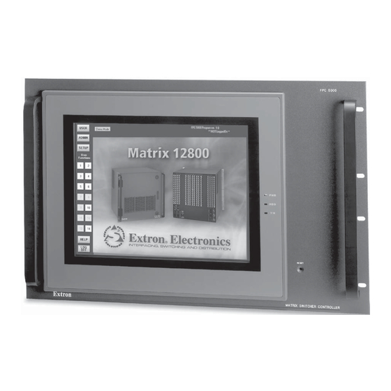
- Page 1 FPC 5000 Matrix 12800 Switcher Front Panel Controller 68-556-05 Rev. A Printed in the USA 05 03...
- Page 2 Precautions Safety Instructions • English Warning This symbol is intended to alert the user of important operating and maintenance Power sources • This equipment should be operated only from the power source indicated on the product. This equipment is intended to be used with a main power system with a grounded (servicing) instructions in the literature provided with the equipment.
-
Page 3: Table Of Contents
Save, recall, or delete a global preset Save, recall, or delete a room preset ................3-19 ..................3-19 Name a global or room preset Mute screen ........................3-20 DSVP screen ........................3-21 FPC 5000 Front Panel Controller • Table of Contents... - Page 4 Blank button ........................3-36 Subnetting — A Primer ....................3-37 68-556-05 Rev. A Printed in the USA 05 03 All trademarks mentioned in this manual are the properties of their respective owners. FPC 5000 Front Panel Controller • Table of Contents...
-
Page 5: Chapter 1 • Introduction
FPC 5000 Front Panel Controller Chapter One Introduction About the Front Panel Controller About the Matrix 12800 System Definitions of Matrix Switcher Terms... -
Page 6: About The Front Panel Controller
Introduction, cont’d About the Front Panel Controller The Extron FPC 5000 Front Panel Controller (figure 1-1) is an optional element of the Matrix 12800 family of matrix switchers. The FPC 5000 is a rack-mountable device that provides front panel control of the matrix, including configuration of the inputs and outputs and control of additional system features. -
Page 7: About The Matrix 12800 System
POWER INPUT ANAHEIM, CA MADE IN USA LISTED 1T23 I.T.E. CAUTION For protection against risk of fire, replace only with same type and rating of fuse. Figure 1-2 — Typical Matrix 12800 system application FPC 5000 Front Panel Controller • Introduction... -
Page 8: Definitions Of Matrix Switcher Terms
• FPC 5000 Front Panel Controller — A rack-mountable 7U device that permits front panel configuration of the inputs and outputs and control of additional system features. -
Page 9: Chapter 2 • Fpc Installation And Operation
FPC 5000 Front Panel Controller Chapter Two FPC Installation and Operation Installation Overview Unpacking and Assembling the Front Panel Controller Rack Mounting the FPC Assembly Rear Panel Connections Front Panel Features and Operation Upgrading the Software... -
Page 10: Installation Overview
The FPC 5000 assembly consists of the FPC computer and a rack-mountable, 7U high, 19” wide metal panel. As part of a complete Matrix 12800 system, the FPC 5000 can be installed in a rack or a cabinet with the rest of the system BMEs. The controller is connected to the Ethernet port of a switching BME. - Page 11 Mounting case. Block Figure 2-2 — Computer and panel mounting block installation FPC 5000 Front Panel Controller • FPC Installation and Operation...
- Page 12 Lift the FPC computer and tighten each screw until the panel is firmly flush against the back side of the FPC computer’s LCD panel (figure 2-4). Figure 2-4 — Fully assembled Front Panel Controller FPC 5000 Front Panel Controller • FPC Installation and Operation...
-
Page 13: Rack Mounting The Fpc Assembly
Insert the controller assembly into the rack, align the holes in the mounting panel with those of the rack. Secure the controller assembly to the rack using the supplied machine screws. Rear Panel Connections All connectors are on the rear of the FPC 5000 (figure 2-5). COM3 COM4 COM2... - Page 14 AC power input connector — Connect a standard IEC power cord between the rear panel AC power input connector and a 100 to 240VAC, 50 Hz or 60 Hz power source. FPC 5000 Front Panel Controller • FPC Installation and Operation...
- Page 15 2 minutes, observe that the LCD touch panel displays the FPC start-up screen (figure 2-8). See chapter 3, Matrix 12800 Operation, for using the FPC to operate the Matrix 12800 system. Figure 2-8 — FPC 5000 Start-up screen FPC 5000 Front Panel Controller • FPC Installation and Operation...
-
Page 16: Cabling And Rj-45 Connector Wiring
FPC Installation and Operation, cont’d Cabling and RJ-45 connector wiring It is vital that your cable between the FPC 5000 and the Matrix 12800 BME 0 or LAN be the correct cable, and that it be properly terminated with the correct pinout. -
Page 17: Front Panel Features And Operation
Front Panel Features and Operation Other than the power switch, the remaining control and all of the FPC 5000 indicators are on the front panel (figure 2-10). FPC 5000 RESET MATRIX SWICHER CONTROLLER Figure 2-10 — Front panel control and indicators LCD touch panel —... -
Page 18: Upgrading The Software
CD-ROM. Upgrade the FPC software as follows: If necessary, log the FPC 5000 on to the Matrix 12800 system as an administrator. See Starting Up the Controller and Logging In and Out in chapter 3, Matrix 12800 Operation. - Page 19 Support the CD tray from behind with one hand while you snap the program CD off of the tray spindle. Gently push the CD tray back into the FPC computer until it locks in place. FPC 5000 Front Panel Controller • FPC Installation and Operation 2-11...
- Page 20 FPC Installation and Operation, cont’d 2-12 FPC 5000 Front Panel Controller • FPC Installation and Operation...
-
Page 21: Chapter 3 • Matrix 12800 Operation
FPC 5000 Front Panel Controller Chapter Three Matrix 12800 Operation Introduction Operating the Touch Panel Starting Up the Controller and Logging In and Out Demo Mode Navigating the Screens User Screens Admin Screens Setup Screens Subnetting — A Primer... -
Page 22: Introduction
Matrix 12800 Operation Matrix 12800 Operation, cont’d Introduction This chapter details operation of a Matrix 12800 system using an FPC 5000 front panel controller. The chapter assumes that the Matrix 12800 is properly installed, virtualized, and operating correctly. The FPC 5000 software runs in an FPC computer that communicates with the... -
Page 23: Using The Keypads
Touch and drag on either the slider or touch the scroll up ( ) or scroll down ( ) buttons until the desired output is visible. • Touch the desired output. The keypad field displays the selected output. FPC 5000 Front Panel Controller • Matrix 12800 Operation... -
Page 24: Starting Up The Controller And Logging In And Out
The IP Connection screen appears (figure 3-5). Figure 3-5 — Address and password entry Decide whether you need to edit the FPC 5000’s IP Address and Subnet Mask fields (see the guidelines below). If you need to edit the fields, proceed to step 5. - Page 25 (figure 3-6). Figure 3-6 — FPC 5000 TCP/IP Properties screen On this screen, you can direct the FPC 5000 to obtain its IP address from a Dynamic Host Configuration Protocol (DHCP) server (if the network is DHCP capable), reenter the factory defaults, or directly enter an IP address and subnet mask value.
- Page 26 If the switcher is not password protected, proceed to step 8. Touch the Password field. The on-screen keyboard appears. Enter the administrator or user password by touching the correct characters on the keyboard. Passwords are case sensitive. FPC 5000 Front Panel Controller • Matrix 12800 Operation...
-
Page 27: Demo Mode
Matrix 12800 with only user capabilities. If an incorrect IP address or password was entered, the controller beeps and displays either FPC 5000 was unable to connect to IP address: or Password rejected! Please try again. Touch the gray OK button to return to the IP Connection screen. - Page 28 Make Ties Screen User Screens Administration Screens Adminstration Screens See figure 3-7b Setup Screens Setup Screens See figure 3-7b Figure 3-7a — FPC 5000 Startup screen and menu flowchart (part 1) FPC 5000 Front Panel Controller • Matrix 12800 Operation...
- Page 29 E-mail Screen User Screens Miscellaneous Status Adminstration Screens Screen Screen Setup Screens Setup Screens Audio Screen Reset Screen Delay Screen Figure 3-7b — FPC 5000 Startup screen and menu flowchart (part 2) FPC 5000 Front Panel Controller • Matrix 12800 Operation...
-
Page 30: User Screens
• View which output(s) is/are tied to a selected input on the View Ties: outputs-by-input selection screen ( • View all ties on either View Ties: alternate view screen ( 3-10 FPC 5000 Front Panel Controller • Matrix 12800 Operation... - Page 31 Figure 3-8 — View ties screens flowchart FPC 5000 Front Panel Controller • Matrix 12800 Operation 3-11...
-
Page 32: Viewing Inputs Tied To A Specified Output
Observe that the input tied to the selected output is displayed in the Input Video and/or Input Audio field. To view the input tied to another output, repeat steps 4 and 5. 3-12 FPC 5000 Front Panel Controller • Matrix 12800 Operation... -
Page 33: Viewing Outputs Tied To A Specific Input
This gives you an easy way to see all of the outputs tied to an input at a glance. FPC 5000 Front Panel Controller • Matrix 12800 Operation 3-13... -
Page 34: Creating Ties
The Change View button does not change. Make Ties: alternate view screen Figure 3-9 — Make ties screens flowchart 3-14 FPC 5000 Front Panel Controller • Matrix 12800 Operation... -
Page 35: Creating Ties Using The Make Ties: Dual Keypad Screen
Matrix 12800, the number is displayed in red in the keypad display. Changes do not take affect until you press the Take button. For an immediate tie, proceed to step 7. FPC 5000 Front Panel Controller • Matrix 12800 Operation 3-15... -
Page 36: Creating Ties Using The Make Ties: Alternate View Screen
The Queue, Cancel, and Take buttons appear on the screen. Changes do not take affect until you press the Take button. For an immediate tie, proceed to step 7. 3-16 FPC 5000 Front Panel Controller • Matrix 12800 Operation... -
Page 37: Preset Screens
Matrix 12800 Wideband, Sync, or Audio Switchers User’s Manual, part #68-556-01. You cannot create rooms or assign outputs to the room using the FPC 5000. When you touch the amber Preset button , the FPC displays the Global Preset screen by default ( on figure 3-10). - Page 38 Room and selects the Room Preset screen when touched. On the Room Preset screen, this button reads Global and selects the Global Preset screen. Room Presets screen Figure 3-10 — Preset screens flowchart 3-18 FPC 5000 Front Panel Controller • Matrix 12800 Operation...
-
Page 39: Save, Recall, Or Delete A Room Preset
Touch the on-screen keyboard’s Enter key to accept the name and dismiss the keyboard from the display. Or, touch the on-screen keyboard’s Cancel key to dismiss the keyboard without accepting the name change. FPC 5000 Front Panel Controller • Matrix 12800 Operation 3-19... -
Page 40: Mute Screen
S-video, and composite video do not use a sync BME, so RGB mute is not available for these formats. RGB mute buttons that are not available are marked by “n/a” 3-20 FPC 5000 Front Panel Controller • Matrix 12800 Operation... -
Page 41: Dsvp Screen
BME are marked by “n/a” in the horizontal and vertical frequency fields . Update the DSVP screen to display fresh frequency readings by touching the green Update button. FPC 5000 Front Panel Controller • Matrix 12800 Operation 3-21... -
Page 42: Admin Screens
• Components that are not installed are indicated in white. If a component fails or is removed, the display shows the change in status the next time you update it. 3-22 FPC 5000 Front Panel Controller • Matrix 12800 Operation... -
Page 43: Status Screen, Bme Area
Remotes buttons. Update the Remotes screen to display the latest remote keypad configuration by touching the green Update button. Return to the Status screen by touching the green Return button. FPC 5000 Front Panel Controller • Matrix 12800 Operation 3-23... -
Page 44: Tcp/Ip Screen
Administrators have full access to all Matrix 12800 editing functions. Users cannot change any settings on the TCP/IP screen. Editing many of the TCP/IP settings while connected via the FPC 5000 can immediately disconnect the user from the Matrix 12800. Extron recommends editing these fields using the switcher’s RS-232/422 link (refer to the Matrix... -
Page 45: Password Fields
Matrix 12800 uses to access the mail server if the Matrix 12800 and the mail server are not on the same subnet. The Gateway IP Address field has the same validity rules as the Matrix IP address. FPC 5000 Front Panel Controller • Matrix 12800 Operation 3-25... -
Page 46: Subnet Mask Field
Matrix 12800 e-mail notification settings. Figure 3-16 — E-Mail screen There are two levels of FPC 5000 password protection: administrator and user. Administrators have full access to all Matrix 12800 editing functions. Users cannot change any settings on the e-mail screen. -
Page 47: Mail Server Ip Address Field
The None radio button is handy for temporarily removing personnel from the e-mail list when they are unavailable, such as on travel or vacation. FPC 5000 Front Panel Controller • Matrix 12800 Operation 3-27... -
Page 48: Miscellaneous Screen
Admin > purple Misc buttons. Figure 3-17 — Miscellaneous screen There are two levels of FPC 5000 password protection: administrator and user. Administrators have full access to all Matrix 12800 editing functions. Users cannot change any function key programming, calibrate the touch screen, or upgrade the FPC software. -
Page 49: File Manager Screen
Two asterisks (**) mark the selected display order. The default listing is alphabetically, by file name. To refresh the file display, touch the green Update button. To return to the Miscellaneous screen, touch the green Return button. FPC 5000 Front Panel Controller • Matrix 12800 Operation 3-29... -
Page 50: Function Keys Screen
Touch the Name field for the button you want to program (Key 1 = User Function button 1). The on-screen keyboard appears. Enter the desired function name using the on-screen keyboard. 3-30 FPC 5000 Front Panel Controller • Matrix 12800 Operation... - Page 51 Touch the green Take button to accept the changes or touch the green Cancel button to reject the changes. Touch the green Return button to return to the Miscellaneous screen. FPC 5000 Front Panel Controller • Matrix 12800 Operation 3-31...
-
Page 52: I/O Physical Connectors Screen
In this example, , 0/001 indicates that the physical output connector for plane 1 (red) is connector 001 on BME 0. To return to the Miscellaneous screen, touch the green Return button. 3-32 FPC 5000 Front Panel Controller • Matrix 12800 Operation... -
Page 53: Naming Inputs And Outputs
Reset screen. The Delay screen, Audio screen, and most of the resets are reserved to personnel logged on as administrators rather than users. Users can view, but not change these settings. FPC 5000 Front Panel Controller • Matrix 12800 Operation 3-33... -
Page 54: Delay Screen
To decrease the RGB delay for a specific output, touch the associated - button. The graphic bar is inoperable and the + and - buttons are grayed out (not available) when the video output format is component video, S-video, or composite video. 3-34 FPC 5000 Front Panel Controller • Matrix 12800 Operation... -
Page 55: Audio Screen
To decrease (attenuate) the audio level for a specific input, touch the - button. Audio attenuation is indicated in red. • An audio level of 0dB, no gain or attenuation, is indicated in magenta. FPC 5000 Front Panel Controller • Matrix 12800 Operation 3-35... -
Page 56: Reset Screen
Audio settings — Resets (clears) all audio gain and attenuation settings. Factory defaults — Resets the switcher to factory defaults. Leaves virtualization and room mapping intact. Blank button Reserved for future use. 3-36 FPC 5000 Front Panel Controller • Matrix 12800 Operation... -
Page 57: Subnetting - A Primer
IP address fields and subnet mask fields and subfields. In order for the FPC 5000 and the Matrix 12800 BME to communicate using TCP/IP protocol, these devices must be on the same subnet and communicate directly, without going through a gateway. - Page 58 Matrix 12800 Operation, cont’d 3-38 FPC 5000 Front Panel Controller • Matrix 12800 Operation...
- Page 59 Extron’s Warranty Extron Electronics warrants this product against defects in materials and workmanship for a period of three years from the date of purchase. In the event of malfunction during the warranty period attributable directly to faulty workmanship and/or materials, Extron Electronics will, at its option,...
- Page 60 Anaheim, CA 92805 3821 AH Amersfoort PM Industrial Building 3-9-1 Kudan Minami The Netherlands Singapore 368363 Chiyoda-ku, Tokyo 102-0074 Japan 714.491.1500 +31.33.453.4040 +65.6383.4400 +81.3.3511.7655 www.extron.com Fax 714.491.1517 Fax +31.33.453.4050 Fax +65.6383.4664 Fax +81.3.3511.7656 © 2003 Extron Electronics. All rights reserved.
Need help?
Do you have a question about the FPC 5000 and is the answer not in the manual?
Questions and answers