
Related Manuals for Advantech PWS-1419


Summary of Contents for Advantech PWS-1419
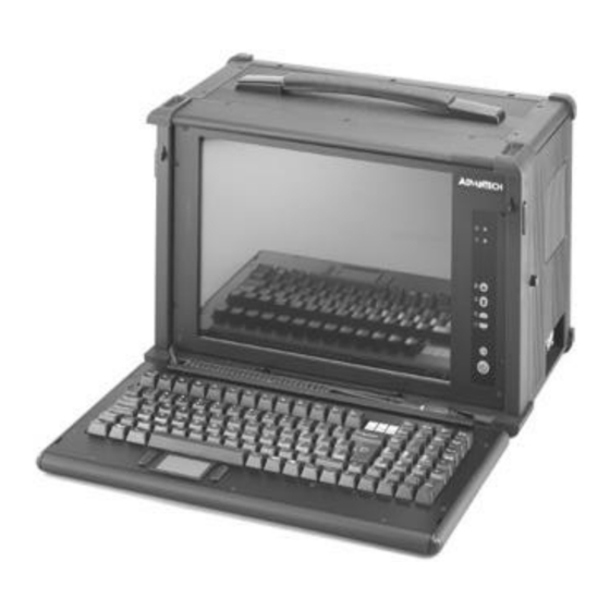
- Page 1 PWS-1409/1419 User’s Manual PWS-1419/1409 9-slot 14.1” TFT LCD Portable Worstation Advantech Portable Workstation User’s Manual...
-
Page 2: Safety Instructions
PWS-1409/1419 User’s Manual The information contained in this document is believed to be accurate. However, no responsibility is assumed for its use, nor for any infringements of patents or other rights of third party which may result from its use. This information is subject to change without any notice. -
Page 3: Table Of Contents
PWS-1409/1419 User’s Manual Chapter 1 Getting Started 1-1 Specification 1-2 Before You Start 1-3 Precautions 1-3-1 Power Connections 1-3-2 Non-Autosensing Power Supply 1-3-3 ATX Power Switch 1-3-4 Ventilation 1-3-5 Care for the LCD 1-4 Tools and Supplies Needed 1-5 Subassembly Contents 1-6 Parts Contents 1-6-1 Optional Slim FDD, CD ROM 1-6-2 Optional Slim FDD kit... - Page 4 PWS-1409/1419 User’s Manual 2-7 Connecting the Power Connector 2-8 Installing the Slim CD ROM to the CD ROM Cage 2-9 Installing the CD ROM Cage 2-10 Installing Drives in the Drive Cage 2-11 Installing the Hard Drive 2-12 Installing the Slim Floppy Disk Drive 2-13 Installing the Drive Cage into the Case 2-14 Installing the SBC 2-14-1 Setting your SBC Jumpers...
- Page 5 4-1-1 Systems with ATX Power Supply 4-2 OSD Controls 4-2-1 Adjusting the OSD Parameters 4-3 Changing Filter for the internal Fan 4-3-1 PWS-1419 4-3-2 PWS-1419 Appendix A. Trouble shooting A-1 Trouble Shooting Techniques A-1-1 No screen after pressing front power switch...
- Page 6 PWS-1409/1419 User’s Manual Chapter 1 Getting Started 1-1 Specification 1-2 Before You Start 1-3 Precautions 1-3-1 Power Connections 1-3-2 Non-Autosensing Power Supply 1-3-3 ATX Power Switch 1-3-4 Ventilation 1-3-5 Care for the LCD 1-4 Tools and Supplies Needed 1-5 Subassembly Contents 1-6 Parts Contents 1-6-1 Optional Slim FDD, CD ROM 1-6-2 Optional Slim FDD kit...
- Page 7 ABS plastic housing with aluminum internal chassis. ( for PWS -1409 only) Environment Operating temperature: -8C to 60C, 10-80% humidity Storage temperature: -20C to 60C, 5-95% humidity Dimensions & Weight PWS- 1409 PWS-1419 Dimensions: 15.7”/399mm (W) Dimensions: 16.6”/421mm (W) 13.2”/335mm (H) 12.1”/282mm (H) 10.4”/ 264mm (D) 9.1”/ 230mm (D)
-
Page 8: Before You Start
PWS-1409/1419 User’s Manual 1-2 Before You Start The major component of the subassembly is the chassis, which comes in two mod- els—8x ISA/ 1 CPUslot or 4 x PCI/ 4 ISA/1 CPU slot Passive Backplane. The chassis comes pre-assembled with an active matrix LCD, LCD controller, power supply, keyboard, ventilation fans and internal speaker. -
Page 9: Specification
PWS-1409/1419 User’s Manual 1-3-4 Ventilation The chassis comes with three intake fans and one power supply exhaust fan providing cooling and air flow. When operating the system, never block any ventilation openings. Always leave enough room around the chassis to allow adequate air flow. 1-3-5 Care for the LCD The chassis comes with a pre-assembled active matrix LCD. -
Page 10: Optional Slim Fdd, Cd Rom
PWS-1409/1419 User’s Manual 1-6-1 Optional Slim FDD, CD ROM Optional Slim Floppy Disk Kit 1. Floppy disk power cable 2. Floppy interface board 3. Floppy disk signal cable (from interface to disk) 4. Slim floppy disk 1-6-2 Optional Slim CD ROM Disk 1. -
Page 11: Identifying Parts And Controls
1-7 Identifying Parts and Controls 1-7-1 Opening the Side Access Covers 1-7-1-a PWS-1419 The side access covers provide side impact protection for to the chassis. The access covers must be opened to access the external drive bays and I/O connectors. -
Page 12: Side View
PWS-1409/1419 User’s Manual 1-7-2 Side Views 1-7-2-a PWS-1419 Use the photo below to identify components and I/O ports that are accessible from the two sides of the 1419T chas sis. The illustration shows the external connectors and components of a completely assembled SBC system. Your subassembly has only knockout holes instead. -
Page 13: Front View
The CDROM is on the right disk. side of the panel 1-7-3 Front View 1-7-3-a PWS-1419 You access the front panel c ontrols by first disengaging the keyboard. Disengage the keyboard from the latches by sliding the latch tabs on both sides of the chassis upwards as shown and simultaneously pull the top part of the key board away from the chassis. -
Page 14: 1-7-3-B Pws1409
PWS-1409/1419 User’s Manual 1-7-3-b PWS-1419 You access the front panel controls by first disengaging the keyboard. Disengage the keyboard from the latches by sliding the latch tabs on the bottom sides of the keyboard towards the center as shown and simultaneously pull the top part of the keyboard away from the chassis. -
Page 15: Detaching The Keyboard
PWS-1409/1419 User’s Manual 1-8 Detaching the Keyboard 1-8-1 PWS- 1419 The keyboard is detachable. Normally it’s locked to the chassis by two latch bolts. You can detac h the keyboard by sliding both release pegs towards each other, com- pressing the latch bolts until they slide out of the slots. Pull the keyboard away from the chassis and release the pegs. -
Page 16: 1-8-2-B The Optional Industrial Silicon Rubber Keyboard
PWS-1409/1419 User’s Manual Chapter 2 PWS-1409T Construction 2-1 Opening The Chassis 2-1-1 Removing the Back Cover 2-1-2 Removing the Card Stabilizers 2-2 Identifying the Internal Parts 2-3 Removing the CD ROM Cage 2-4 Removing the Hard Driver and Slim Floppy Drive Cage 2-5 Installing the Backplane 2-6 Installing the Standoffs 2-7 Connecting the Power Connector... -
Page 17: Removing The Card Stabilizers
PWS-1409/1419 User’s Manual Chapter 2 PWS-1409T Construction 2-1 Open the chassis 2-1-1 Removing the Back Cover Face the back of the chassis. Remove all screws as shown. There are 10 screws along the perimeter of the back cover that holds the back cover to the chassis. -
Page 18: Removing The Cd Rom Cage
PWS-1409/1419 User’s Manual 2-3 Removing the CD ROM cage Step 1. Remove screws as shown (1) and then pull out the CD ROM Upper cage. Step 2. Remove screw as shown (2) and then pull out the CD ROM Bottom cage. 2-4 Removing the hard drive and slim floppy Drive cage Lay the chassis on your work area so that you have... - Page 19 PWS-1409/1419 User’s Manual find the mount point of the backplane insert the stand offs Thread clock-wise to insert the standoff revers e to take off the stand off Your package comes with metal standoffs threaded on one end and tapped on the opposite end to receive a mounting screw.
-
Page 20: Connecting The Power Connector
PWS-1409/1419 User’s Manual 2-7 Connecting the power Connector The plug from the power supply will only insert in one orientation. Push down firmly making sure the hook on the terminal block clips onto the plug. Connecting the Chassis Cables The chassis has 3 internal cooling fan to reduce the temperature of the system, connecting the fan power connector to fan adapter board. - Page 21 PWS-1409/1419 User’s Manual What need for install CDROM #1 fix interface board to CD ROM #10 fix CD ROM to CD ROM cage #6 fix CD ROM bottom cage to side of case #7 Fix CD ROM upper cage to back of case 1.
-
Page 22: Installing The Cd Rom Cage
PWS-1409/1419 User’s Manual 2-9 Installing the CD ROM Cage Step 1. Carefully put the drive cage back into the chassis. (fig1) Step 2. Align the side mounting holes. Insert the screw#6 and tighten it Step 3. Align the back mounting holes. Insert the screw#7 and tighten it Step 4. -
Page 23: Installing The Hard Drive
PWS-1409/1419 User’s Manual 2-11 Installing the hard driver The drive cage supports one slim Floppy disk and a 3.5” Hard disk drives. Step 1. Take back the driver cage and take off the screw#5 and washer #3 from your package. Step 2. - Page 24 PWS-1409/1419 User’s Manual Step 3. Pull up the small cage from the slim floppy disk Connect the signal cable Pull up the small cage carefully The cable has pin 1 on the dot point Step 4. Insert the floppy signal cable to slim floppy. Ribbon cables should always be con- nected with the colored stripe (blue point on it) to Pin 1 on the connectors Step 5.
-
Page 25: Installing The Drive Cage Into The Case
PWS-1409/1419 User’s Manual Step10. Connect the signal cable Step11. Connect the power cable 2-13 Installing the Drive cage into the case Step 1. Connec t the hard drive signal cable and power cable Interior space is going to be tightened. While you have the drive cage outside the chassis, plug in hard drive signal and power cable Power supply plugs cable will only insert in one orientation. -
Page 26: Installing The Sbc
PWS-1409/1419 User’s Manual 2-14 Installing the SBC 2-14-1 Setting your SBC Jumpers Before installing the motherboard in the chassis, install the CPU and set any dip-s witch or jumper on the SBC. Since jumper and dip-switch settings are board-specific, consult the manual that comes with the SBC and carefully follow the directions to configure your SBC. -
Page 27: Installing The Add-On Cards
PWS-1409/1419 User’s Manual Connect the signal cable and chassis cable Fix the SBC with screw #2 before fix the SBC 2-15 Installing the Add-on Cards The chass is has 10 slot openings supporting up to nine (one is used by SBC) add-on cards. Follow these steps to install add-on cards Add-on card can be extremely sensitive to electrostatic discharge. -
Page 28: Preparing To Start The System
PWS-1409/1419 User’s Manual Slant the add-on card stabilizer and put it Use the screw removed earlier. Ins ert it into in the case, then set straight and fix it. the threaded hole and tighten it. Use screw #7 to secure it. Step 3. -
Page 29: Closing The
PWS-1409/1419 User’s Manual 1. Connect the VGA Connector 2. Connec t the input device Connect the other connectors for other dev ice such as Ethernet, Audio device….. 2-17-2 Closing the Back Cover Reinstall the back cover and insert the retaining screws. -
Page 30: Chapter 3 Pws-1409 Construction
PWS-1409/1419 User’s Manual Chapter 3 PWS-1409 Construction 3-1 Opening The Chassis 3-1-1 Removing the Back Cover 3-2 Removing the Card Stabilizers 3-3 Identifying the Internal Parts 3-4 Removing the Drive Cage 3-5 Installing the Backplane 3-5-1 Installing the Standoffs 3-6 Connecting the Power Connector 3-7 Installing the Drives to the Drive Cage 3-8 Insttalling the Driver Cage into the Case 3-9 Installing the SBC... -
Page 31: Removing The Card Stabilizers
PWS-1409/1419 User’s Manual Chapter 3 PWS-1409 Construction 3-1 Open the chassis 3-1-1 Removing the Back Cover Face the back of the c hassis. Remove all screws as shown. There are 7 screws along the perimeter of the back cover that holds the back cover to the chassis. Always power down the system. -
Page 32: Installing The Backplane
PWS-1409/1419 User’s Manual 1. speaker 2 case fan 3 fan board 4 LCD power cable 5 audio cable CD audio in 6 driver cage 7 fan cable to SBC 8 CDROM signal cable 9 power supply 10 reset cable 11 audio cable (SBC to speaker) 12 side door 13 mount hole... - Page 33 PWS-1409/1419 User’s Manual find the mount point of the backplane insert the stand offs Thread clock-wise to insert the standoff revers e to take off the stand off Your package comes with metal standoffs threaded on one end and tapped on the opposite end to receive a mounting screw.
-
Page 34: Connecting The Power Connector
PWS-1409/1419 User’s Manual 3-6 Connecting the power Connector The plug from the power supply will only insert in one orientation. Push down firmly making sure the hook on the terminal block clips onto the plug. Connecting the Chassis Cables The chassis has 3 internal cooling fan to reduce the temperature of the system, connecting the fan power connector to fan adapter board. - Page 35 PWS-1409/1419 User’s Manual secure the hard disk to drive cage with screw secure the floppy disk to drivr cage with # 5, insert washer #3 between cage and screw# 2, , same with the other side screw, same with the other side Connect the signal cables Ribbon c ables should always be connected with the colored stripe to...
-
Page 36: Insttalling The Driver Cage Into The Case
PWS-1409/1419 User’s Manual 3-8 Intall the driver cage to case Step 1. Carefully put the drive cage back into the chassis. Step 2. Plugging the case fan power conecttor into the interface board for fan power Step 3. Plugging the power conector for floppy disk and hard disk Step 4. -
Page 37: Installing The Sbc
PWS-1409/1419 User’s Manual 3-9 Installing the SBC 3-9-1 Setting your SBC Jumpers Before installing the motherboard in the chassis, install the CPU and set any dip-switch or jumper on the SBC. Since jumper and dip-switch settings are board-specific, consult the manual that comes with the SBC and carefully follow the directions to configure your SBC. -
Page 38: Installing The Add-On Cards
PWS-1409/1419 User’s Manual Connect the signal cable and chassis cable Fix the SBC with screw #2 before fix the SBC 3-10 Installing the Add-on Cards The chassis has 10 slot openings supporting up to nine (one is used by SBC) add-on cards. Follow thes e steps to install add-on cards Add-on card can be extremely sensitive to electrostatic discharge. -
Page 39: Preparing To Start The System
PWS-1409/1419 User’s Manual Slant the add-on card stabilizer and put it in the case, then set straight and fix it. Use the screw removed earlier. Insert it into Use screw #7 to secure it. the threaded hole and tighten it. Step 3. -
Page 40: Closing The Back Cover
PWS-1409/1419 User’s Manual 1. Connect the VGA Connector 2. Connect the other c onnectors for other device such as Ethernet, Audio device… 3-13 Closing the Back Cover Closing the Back Cover Reinstall the back cover and insert the retaining screws. - Page 41 PWS-1409/1419 User’s Manual Chapter 4 Using The System Controls 4-1 Starting your System 4-1-1 Systems with ATX Power Supply 4-2 OSD Controls 4-2-1 Adjusting the OSD Parameters 4-3 Changing Filter for the internal Fan 4-3-1 PWS-1419 -3-2 PWS-1419...
-
Page 42: Chapter 4 Using The System Controls
PWS-1409/1419 User’s Manual Chapter 4 Using The System Controls 4-1 Starting your System Before starting your system, plug in the power cord and make sure the video and input device connectors are plugged in. Release the keyboard latches and lay it flat on your work area. 4-1-1 Systems with ATX Power Supply If you have an ATX power supply, power up your system by pressing the ATX power switch push button on the front panel of your chassis. -
Page 43: Adjusting The Osd Parameters
PWS-1409/1419 User’s Manual Menu Menu Reset ATX Power 4-2-1 Adjusting the OSD Parameters The OSD consists of a main menu and sub-menus with the following selections: Brightness MENU Manual adjustment the brightness CONTRAST MENU Contrast: Manual adjustment the contrast Sub-CONTRAST: Manual adjustment of individual RGB channel contrast. Position MENU H-size: Adjust the horizontal size Clock phase: Manual adjustment of the sample pixel clock phase. -
Page 44: Pws-1419
Remove the cover, take off the filter Caution: Please make the filter is dry when you restore it 4-3-2 PWS-1419 The internal fan is the entrance of the system air flow. It may contain dust during the long use. Change or clean the filter for the fan will improve the system air flow. Please follow the steps to clean or change the filter. -
Page 45: Appendix A. Trouble Shooting
PWS-1409/1419 User’s Manual Appendix A. Trouble shooting A-1 Trouble Shooting Techniques A-1-1 No screen after pressing front power switch A-1-1-a Power supply fan not spinning A-1-1-b Power supply fan is spinning and LCD has no backlight A-1-1-c Power supply fan is spinning and LCD has backlight and power LED is on A-1-2 LCD screen shows garbage or bad characters or vertical horizontal color lines or bar... -
Page 46: A-1 Trouble Shooting Techniques
PWS-1409/1419 User’s Manual A-1 Trouble Shooting Techniques A-1-1 No screen after pressing front power switch A-1-1-a Power supply fan not spinning: Check power source. Check power cord connection. Check if all power connectors inside the chassis have been properly connected. Check the ATX power switch cable to SBC(or motherboard) have been properly con- nected Check main power switch on power supply (PS-2 power supply for BP-7 model). -
Page 47: A-1-3 Lcd Screen Works Fine In Windows But Acted Funny When Running Certain Programs Or Games
PWS-1409/1419 User’s Manual A-1-3 LCD SCREEN works fine in Windows but acted funny when running certain programs or games: The built-in Intelligent Analog-Digital conversion board (AD board) should adjust the screen to the proper resolution to fill the entire display. However, certain programs or display modes might cause the AD board to not align or sync properly. -
Page 48: Appendix B: Lcd Video Controller
PWS-1409/1419 User’s Manual Appendix B: LCD VIDEO Controller B-1 Introduction B-2 Safety Precautions B-3Configuring Your Controller B-3-1 LCD with TTL Interface B-3-2 LCD wits LVDS Receiver Interface B-4 OSD Controls B-4-1 Adjusting the OSD Parameters... -
Page 49: B-1 Introduction
PWS-1409/1419 User’s Manual Appendix B: LCD VIDEO Controller B-1 Introduction The LCD video controller subassembly is an “in-monitor” design build around a high performance ASIC technology that enable the display of analog VGA signals on a flat panel LCD display. The LCD video board provides all the electronic necessary to drive a TFT flat panel display from VGA (640x480) up to (1280x1024) source. -
Page 50: B-2 Safety Precautions
PWS-1409/1419 User’s Manual The light source for most flat panel displays is a cold cathode fluorescent backlight. These backlights run on high AC voltage provided by an inverter that converts the supplied DC power to AC and steps its voltage up for start-up. Once the backlight is started, the inverter drops the voltage down to its operating level. -
Page 51: B-4-1 Adjusting The Osd Parameters
PWS-1409/1419 User’s Manual Brightness Brightness Contrast Contrast Sub. Contrast Position H. Size Clock Phase Information All Reset H. Position V. Position Information 1024 x 768 H. f 56.4KHz V. f. 70 Hz Follow these steps to activate the on-screen display and make any adjustments to suit your preference: Step 1. - Page 52 PWS-1409/1419 User’s Manual B-4-1-c POSITION H-SIZE: Adjustment of the vertical image size CKOCK PHASE: adjustment of the ADC sample pixel clock. H. POSITION: Adjusts the horizontal image position within the display area of the LCD. V. POSITION: Adjusts the vertical image position within the display area of the LCD. B-4-1-d INFORMATION Shows the current display resolution, horizontal and vertical frequency B-4-1-e Auto adjust:...
Need help?
Do you have a question about the PWS-1419 and is the answer not in the manual?
Questions and answers