
Subscribe to Our Youtube Channel
Related Manuals for Advantech PPC-415 6 Series


Summary of Contents for Advantech PPC-415 6 Series
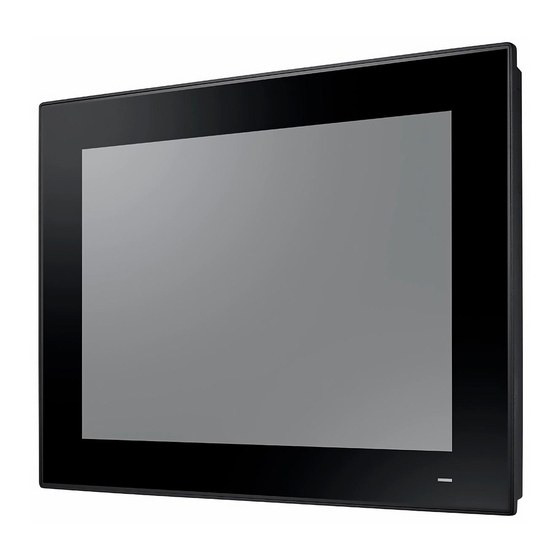
- Page 1 User Manual PPC-415/417/419 EHL 15"/17”/19” Color TFT LCD panel ® PC with Intel Atom™ x6425E Processor...
- Page 2 No part of this manual may be reproduced, copied, translated, or transmitted in any form or by any means without the prior written permission of Advantech Co., Ltd. The information provided in this manual is intended to be accurate and reliable.
- Page 3 This product has passed the CE test for environmental specifications when shielded cables are used for external wiring. We recommend the use of shielded cables. This type of cable is available from Advantech. Please contact your local supplier for ordering information.
- Page 4 Safety Instructions Read these safety instructions carefully. Veuillez lire attentivement ce manuel d'instructions de sécurité. Retain this user manual for future reference. Veuillez conserver ce manuel d'instructions pour référence ultérieure. Disconnect the equipment from all power outlets before cleaning. Use only a damp cloth for cleaning.
- Page 5 AVERTISSEMENT: Ces instructions sont fournies conformément aux normes IEC 704-1. Advantech décline toute responsabilité quant à la précision de toute déclaration contenue dans le présent document. CAUTION: This product is not intended for use by children and is not suitable for use in locations where children are likely to be present (this product is not a toy).
- Page 6 Veuillez ne pas placer les écrans dans le rayonnement solaire direct, dans la haute lumière et dans d ‘autres sources de chaleur.L ‘exposition prolongée dans cet environnement peut entraîner la décoloration et l’ endommagement de l ‘affi- chage. Safety Precautions - Static Electricity Follow these simple precautions to protect yourself from harm and the products from damage.
-
Page 7: Table Of Contents
Contents Chapter General Information ......1 Introduction ....................2 Specifications .................... 2 Table 1.1: Specifications ............. 2 Dimensions ....................4 Figure 1.1 PPC-415-XX6 Dimensions ......... 4 Figure 1.2 PPC-417-XX6 Dimensions ......... 4 Figure 1.3 PPC-419-XX6 Dimensions ......... 5 Chapter System Installation & Setup ....7 Quick Installation Guide ................ - Page 8 2.11 Cabinet Installation and Grounding............26 Figure 2.32Cabinet Installation........... 26 Figure 2.33System Wiring Diagram..........26 2.12 Optional Module Installation..............27 Figure 2.34 ................. 27 Figure 2.35 ................. 27 Figure 2.36 ................. 28 Figure 2.37 ................. 28 Figure 2.38 ................. 29 Figure 2.39 .................
- Page 9 Figure 4.13.................. 48 Figure 4.14.................. 49 4.2.8 Deep Sleep ................. 49 Figure 4.15.................. 49 Figure 4.16.................. 50 4.2.9 Security ..................50 Figure 4.17.................. 50 4.2.10 Boot..................... 51 Figure 4.18.................. 51 4.2.11 Save and Exit................52 Figure 4.19.................. 52 Appendix A PCI/PCI-E ..........53 PCI/PCI-E....................
- Page 10 PPC-415/417/419 EHL User Manual...
-
Page 11: Chapter 1 General Information
Chapter General Information This chapter gives background information on the PPC-415/417/ 419 panel PC. Introduction Specifications Dimensions... -
Page 12: Introduction
Introduction Advantech’s PPC-415/417/419 (15”/17”/19”) fanless panel PCs are powered by an Intel® Atom™ x6425E processor that delivers high-performance computing and sup- ports a wide operating temperature (-20 ~ 60 0 °F) and wide power input °C/-4 ~ 14 range (9 ~ 32 V ). - Page 13 Table 1.1: Specifications CFast card (optional module) Other Expansions 2 x DB9 for two RS-232 or one RS-232 and one GPIO (optional module) OS Support ® Microsoft Windows 10/11(64-bit), Win10 IOT LTSC, Linux Power Consumption * 50W 60 W 55 W Input Voltage 9 ~ 32 VDC, 10 A ~ 3 A (19Vdc, 4.74A optional Adapter) * Test conditions of power consumption for PPC-415-XX6:...
-
Page 14: Dimensions
Dimensions PPC-415-XX6 Series Unit:mm Panel Cutout Dimensions:382x303(15.03x11.92in) Figure 1.1 PPC-415-XX6 Dimensions Warning! To prevent personal injury and product damage, always use suitable mounting apparatus. VESA screw specifications: Type: M4; Screw depth: 8 mm PPC-417-XX6 Series 184.71 Panel Cutout Dimensions: 427 x 347 mm (16.81 x 13.66 in) Figure 1.2 PPC-417-XX6 Dimensions Warning! To prevent personal injury and product damage, always use suitable mounting apparatus. - Page 15 PPC-419-XX6 Series 178.81 Panel Cutout Dimensions: 444 x 370 mm (17.48 x 14.56 in) Figure 1.3 PPC-419-XX6 Dimensions Warning! To prevent personal injury and product damage, always use suitable mounting apparatus. VESA screw specifications: Type: M4; Screw depth: 8 mm PPC-415/417/419 EHL User Manual...
- Page 16 PPC-415/417/419 EHL User Manual...
-
Page 17: Chapter 2 System Installation & Setup
Chapter System Installation & Setup Quick Installation Guide Installation Procedures Memory Card Installation SSD Installation Mini SATA Installation Wireless LAN Card Installation Riser Card Installation AT/ATX Function Switch Mount Bracket Installation ... -
Page 18: Quick Installation Guide
Quick Installation Guide Before setting up the PPC-415/417/419 panel PC, take a moment to familiarize your- self with the functions and locations of the controls, drives, connectors, and ports (as shown in the figures below). When placed upright on the desktop, the PPC-415/417/ 419 panel PC should appear as shown in Fig. - Page 19 1. Antenna holes 2. Panel mount hook holes 3. Speakers (right and left) 4. CPU heatsink 5. Ground screw 6. Optional module expansion slot Note! VESA screw specifications: Type: M4; Screw depth: 8 mm I/O Connectors Figure 2.3 I/O Connectors A: 1 x Expansion slot (PCI or PCIe x1) G: Power Button B: Mic-in/Line-Out...
-
Page 20: Installation Procedures
Installation Procedures 2.2.1 Connecting the Power Cable The PPC-415/417/419 panel PC features a DC power socket (9 ~ 32 V). When con- necting the power cable, hold the cable at the plug end. Follow the procedures outlined below to ensure correct setup. Before connecting the power cable, check that the system’s power mode setting is configured according to your requirements. -
Page 21: Memory Card Installation
Memory Card Installation Remove the 9 screws (circled in red) and take out the clip from the rear cover to remove the rear cover (see Figs. 2.5 and 2.6). Figure 2.5 Figure 2.6 PPC-415/417/419 EHL User Manual... - Page 22 Remove the eight screws on the heatsink and remove the heatsink. Figure 2.7 Insert the memory card into the slot (highlighted in the red square in Fig. 2.8). Retrieve the thermal pad provided in the accessory box and install it directly atop the memory card and CPU.
-
Page 23: Ssd Installation
SSD Installation Follow Step 1 of Section 2.3 to remove the rear cover (see Figs. 2.5 and 2.6). Remove the six screws (circled in red) to remove the VESA mount plate (see Fig. 2.9). Figure 2.9 Remove the four screws (circled in red in Fig. 2.10) to remove the SSD cover. Figure 2.10 PPC-415/417/419 EHL User Manual... - Page 24 Retrieve four screws from the accessory box and use them to affix the SSD to the SSD bracket (see Fig. 2.11). Then connect SSD cable to the SSD (see Fig 2.12). Figure 2.11 Figure 2.12 PPC-415/417/419 EHL User Manual...
-
Page 25: Installation
M.2 Installation Follow Steps 1 and 2 of Section 2.4 to remove the rear cover and VESA mount plate. The disassembled machine should appear as shown in Fig. 2.13. Figure 2.13 To install a 22X80mm size M.2 card, insert the M.2 card into the correct main- board slot, and affix it in place using one M3x5L screws provided in the acces- sory box. - Page 26 To install a 22X42 mm size M.2 card, add a copper cylinder screw (see Fig. 2.15) which provided in the accessory box . Then insert the M.2 card into the correct mainboard slot, and affix it in place using one M2.5x3L screws. Figure 2.15 Figure 2.16 Replace the VESA mount plate and rear cover and secure with screws.
-
Page 27: Wireless Lan Card Installation
Wireless LAN Card Installation Follow Steps 1 and 2 of Section 2.4 to remove the rear cover and VESA mount plate. Affix the wireless LAN card to the bracket using the screws provided with the Wi-Fi module (model name: PPC-WLAN-D2). Figure 2.17 Insert the wireless LAN card into the appropriate mainboard slot. - Page 28 Connect the cables of the wireless LAN card to the antenna holder. Note the installation direction of the cable end and nut/washer. Figure 2.19 Secure the assembled antenna holder to the top of the panel PC. Then connect the cables to the wireless LAN card (see Fig. 2.20). Figure 2.20 PPC-415/417/419 EHL User Manual...
- Page 29 Figure 2.21 Replace the VESA mount plate. Take out two plugs located at the top of the rear cover (see Fig. 2.22) for the antenna connectors. Then replace the rear cover and secure in place using screws. Finally, attach the antennas to the two antenna connectors located at the top of the panel (see Fig.
- Page 30 Figure 2.23 Note! The wireless LAN card shown in the above images to demonstrate the installation procedures is the PPC-WLAN-D2 Wi-Fi module produced by Advantech. PPC-415/417/419 EHL User Manual...
-
Page 31: Install 4G/5G Devices
Install 4G/5G Devices Follow Steps 1 and 2 of Section 2.4 to remove the rear cover and VESA mount plate. The disassembled machine should appear as shown in Fig. 2.13. Add a copper cylinder screw (see Fig. 2.24) provided in the accessory box. Then insert the M.2 card into the correct mainboard slot, and affix it in place using one M2.5x3L screws. - Page 32 Fix the antenna to the bracket (bracket PN is 1960104428N001, need to pur- chase separately).Then Fix the antenna Bracket and connect the antenna. Figure 2.26 PPC-415/417/419 EHL User Manual...
-
Page 33: Riser Card Installation
Riser Card Installation Follow Step 1 of Section 2.3 to remove the rear cover of the panel PC (refer to Figs. 2.5 and 2.6). Insert the riser card into the slot, and secure in place using two screws (see Fig. 2.27). -
Page 34: At/Atx Function Switch
AT/ATX Function Switch Located at the rear of the panel PC is an AT/ATX function switch that allows users to choose between AT/ATX mode without removing the rear cover (see Figs. 2.29 and 2.30). Figure 2.29 ATX Mode Figure 2.30 AT Mode PPC-415/417/419 EHL User Manual... -
Page 35: Mount Bracket Installation
2.10 Mount Bracket Installation Correct Wrong Install the panel PC in the cabinet and retrieve the wall mount hooks. Insert the wall mount hooks into the bezel holes, following the direction arrows above. Secure the wall mount hooks to the wall mount bracket using screws. Figure 2.31 PPC-415/417/419 EHL User Manual... -
Page 36: Cabinet Installation And Grounding
2.11 Cabinet Installation and Grounding Follow these instructions to install the PPC system, and pay attention to the ground pin which should be connected to the earth/ground. PPC system should give the best performance for EMI optimum EMI immunity, ESD immunity, surge immunity, and system isolation. -
Page 37: Optional Module Installation
Step D: Connect the ground pin of PPC system to the cabinet. Note! The wire of the protective earthing conductor shall be green-and-yellow, xx AWG/ 0.75mm2 and connecting to earth of building. Ensure that the voltage of the power source is correct before connecting the equipment to a power outlet. - Page 38 Retrieve the CFast module card from the module case and remove the two screws located at the side (1) of the metal tray. Affix the CFast card to the underside of the metal tray. Then insert the tray in the direction shown in Fig.2.36 (2) and connect the red SATA cable (3).
- Page 39 B. COM Module (98R3C31500E for PPC-415/417; 98R3C31900E for PPC-419) Installation There are two options for COM module installation: Via the I/O or via the expansion slot. Both methods of installation are explained below. B.1 Via the I/O Follow Steps 1 ~ 3 of Subsection A. Retrieve the two COM connectors from the module case and affix them to the I/O shield at the side of the device using two screws.
- Page 40 Figure 2.40 B.2 Via the expansion slot Follow Steps 1 ~ 2 of Subsection A. Remove the two screws on the riser card and the screw on the expansion slot shield (see Fig. 2.56) to retrieve the expansion slot shield. Figure 2.41 PPC-415/417/419 EHL User Manual...
- Page 41 Remove the two COM connectors from the module case and affix them to the expansion slot shield (as shown in Fig. 2.57). Figure 2.42 Affix the shield with COM connectors to the expansion slot backplate and secure in place using a screw. Connect the two COM cables to the mainboard and secure with cable ties (see Fig.
- Page 42 PPC-415/417/419 EHL User Manual...
-
Page 43: Chapter 3 Jumper Settings
Chapter Jumper Settings Jumpers and Connectors External COM Ports and Pin Definitions... -
Page 44: Jumpers And Connectors
Jumpers and Connectors CN36 M2E1 CN19 CN20 CN26 JCMOS1 CN28 CN22 Figure 3.1 Table 3.1: Jumpers and Connectors Connector Function CN36 M.2 B-Key 2242/2280/3042/3052 M2E1 M.2 E-Key 2230 JCMOS1 RTC Select Resistance Touch Power Select CN19 COM 4 CN20 COM 5 CN26 GPIO CN22... -
Page 45: Atx/At Select
3.1.2 ATX/AT Select Table 3.3: Function 1-3pin ATX power (Default*) 2-3pin AT power 3.1.3 Power Button Connection Table 3.4: CN28 Function Power Button Used as a switch if connected to an extension cord. 3.1.4 Touch Power Select Table 3.5: Function Open Capacitive PCT Closed... -
Page 46: External Com Ports And Pin Definitions
External COM Ports and Pin Definitions COM1 COM2 COM3 Figure 3.2 COM1/COM2: RS-232 COM1/COM2 Pin 9 is set as “RI” by default. This setting can be changed to 5V or 12V output using a jumper. Table 3.6: COM1/COM2 COM4/COM5 GPIO GPIO4 GPIO0 GPIO5... -
Page 47: Com1 /Com2 Pin 9 Power Select
3.2.1 COM1 /COM2 Pin 9 Power Select Table 3.7: CN22 Function (1-3)/(2-4) pin COM1/COM2 RI (Default*) (3-5)/(4-6) pin COM1/COM2 pin 9 5V (7-9)/(8-10) pin COM1/COM2 pin 9 12V 3.2.2 COM3 COM 3: RS-422/485 with isolated 1000 VDC (configurable via the BIOS Setup Util- ity). - Page 48 PPC-415/417/419 EHL User Manual...
-
Page 49: Chapter 4 Software Setup
Chapter Software Setup Installing Drivers BIOS Setup Utility... -
Page 50: Installing Drivers
When you install the system for the first time, please install the corresponding drivers in advance to make sure all the functions run normally. Please select the drivers to be installed based on the OS you use. Please go to the Advantech. BIOS Setup Utility 4.2.1... -
Page 51: Cpu Configuration
4.2.2 CPU Configuration Figure 4.2 Figure 4.3 CPU Configuration CPU type and frequency. PPC-415/417/419 EHL User Manual... -
Page 52: Com3 Mode Selection (Rs422/Rs485)
Intel Virtualization Technology This item allows users to enable or disable Intel Virtualization Technology. When enabled, a VMM can utilize additional hardware capabilities provided by Vander- pool Technology. 4.2.3 COM3 Mode Selection (RS422/RS485) Select NCT6126D Super IO Configuration in the Advanced tab. Figure 4.4 PPC-415/417/419 EHL User Manual... - Page 53 Select Serial Port 3 Configuration option. Figure 4.5 Select Serial Port 3 Mode option to set the COM3 operation mode as RS422, or RS485. Figure 4.6 PPC-415/417/419 EHL User Manual...
- Page 54 Serial Port 3 Configuration Select Serial Port 3 setting (RS422/RS485) If COM3 mode is set as RS485, the RS485 Auto Flow control option can be Enabled or Disabled. Figure 4.7 Serial Port 3 RS485 Configuration RS485 Auto Flow control option can be (Enabled or Disabled) PPC-415/417/419 EHL User Manual...
-
Page 55: Hardware Monitor
4.2.4 Hardware Monitor Figure 4.8 Figure 4.9 EC Hardware Monitor This page displays all information about system Temperature/Voltage/Current. PPC-415/417/419 EHL User Manual... -
Page 56: Usb Configuration
4.2.5 USB Configuration Figure 4.10 XHCI Hand-off This is a workaround of 0Secs without XHCI hand-off support. The XHCI owner- ship change should be claimed by XHCI driver. USB Mass Storage Driver Support Enable/Disable USB Mass Storage Driver Support PPC-415/417/419 EHL User Manual... -
Page 57: Sata Configuration
4.2.6 SATA configuration Figure 4.11 Figure 4.12 SATA Controller Enable/Disable SATA Device PPC-415/417/419 EHL User Manual... -
Page 58: Wake-On-Lan
SATA Mode Selection Determines how SATA controller(s) operate SATA Controller Speed Indicates the maximum speed the SATA controller can support. (Gen1/Gen2/ Gen3) M.2 B-key Slot Enable or Disable M.2 B-key port Serial ATA Port Enable or Disable Serial ATA port 4.2.7 Wake-on-LAN Select PCH-IO Configuration option in the Chipset tab. -
Page 59: Deep Sleep
Set the Wake On By option to Enabled. Figure 4.14 4.2.8 Deep Sleep Select PCH-IO Configuration option in the Chipset tab. Figure 4.15 Set the Deep Sleep by option to Enabled/Disabled for ERP. PPC-415/417/419 EHL User Manual... -
Page 60: Security
Figure 4.16 4.2.9 Security Figure 4.17 Select Security Setup from the Setup main BIOS setup menu. All Security Setup options, such as password protection and virus protection are described in this sec- PPC-415/417/419 EHL User Manual... -
Page 61: Boot
tion. To access the sub menu for the following items, select the item and press <Enter>: Administrator Password Set the administrator password. 4.2.10 Boot Figure 4.18 Setup Prompt Timeout Number of seconds that the firmware will wait before initiating the original default boot selection. -
Page 62: Save And Exit
4.2.11 Save and Exit Figure 4.19 Save options Save settings and exit system. Default Options Restore default settings. PPC-415/417/419 EHL User Manual... -
Page 63: Pci/Pci-E
Appendix PCI/PCI-E... -
Page 64: Pci/Pci-E
PCI/PCI-E The default 989K821120E PCIe x1-to-PCIe x1 slot provided in the accessory box is shown below. (This riser card is only supported by PPC-415.) The optional 989K821131E PCIe x1-to-PCI slot is shown below. (This riser card is only supported by PPC-415.) The optional 989K821131E PCIe x1-to-PCI slot is shown below. - Page 65 Note! The PPC-415 panel PCs support riser cards with maximum dimension of 176 x 107 mm. The PPC-417/419 panel PCs support riser cards with maximum dimen- sion of 240.0*127 mm. The total load current supported by the PCIe expansion slot is listed below. 12 V 0.5 A 3.3 V...
- Page 66 No part of this publication may be reproduced in any form or by any means, such as electronically, by photocopying, recording, or otherwise, without prior written permission from the publisher. All brand and product names are trademarks or registered trademarks of their respective companies. © Advantech Co., Ltd. 2023...
Need help?
Do you have a question about the PPC-415 6 Series and is the answer not in the manual?
Questions and answers