
Related Manuals for Advantech POC-624-02 Series


Summary of Contents for Advantech POC-624-02 Series
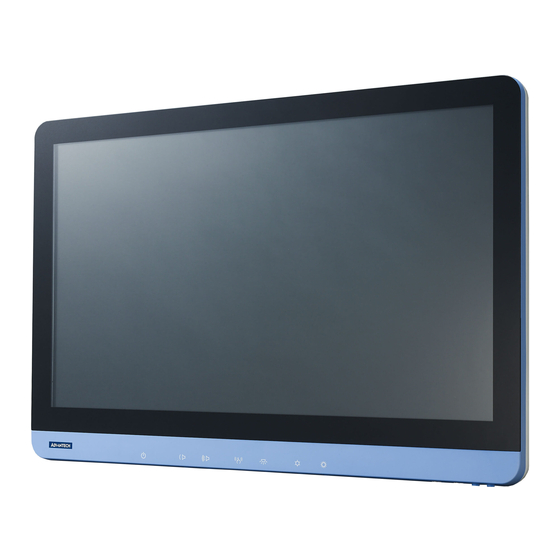
- Page 1 User Manual POC-624-02 Series (AC-In Model) 23.8" Computer with 11th Generation Intel® Processor...
- Page 2 à l'utilisateur ou au patient et endommager l'équipement ou d'autres propriétés. Note! A NOTE provides additional information intended to avoid inconve- niences during operation. Part No. 2008062410 Edition 1 Printed in Taiwan November 2023 POC-624-02 Series User Manual...
- Page 3 Repair of the device may also only be carried out by trained service personnel. Advantech recommends that a service contract be obtained with Advantech Service and that all repairs also be carried out by them. Otherwise, the correct functioning of the device may be compromised.
- Page 4 Caution! When servicing the device, always use replacement parts that are quali- fied to Advantech standards. Advantech Medical cannot warrant or endorse the safe performance of third-party replacement parts for use with our medical device.
- Page 5 UL/CSA listed, length: 1.8m, hospital grade if for the USA/Canada market. Installation is only to be carried out by authorized and trained personnel. The device is intended to be used as SIP/SOP, facing downward. Do not place the power cord where it is difficult to disconnect. POC-624-02 Series User Manual...
- Page 6 évitée, peut entraîner des blessures mineures ou modérées à l'utilisateur ou au patient ou des dommages à l'équipement ou à d'autres biens. AVERTISSEMENT! Une REMARQUE fournit des informations supplémentaires destinées à éviter les inconvénients en cours de fonctionne- ment. POC-624-02 Series User Manual...
- Page 7 étiquettes affichées sur l’appareil. La réparation de l'appareil ne doit être effectuée que par du personnel de ser- vice qualifié. Advantech recommande qu'un contrat de service soit conclu avec le service de maintenance Advantech et que toutes les réparations soient également effectuées par ce dernier.
- Page 8 Attention! Lors de l'entretien de l'appareil, utilisez toujours des pièces de rechange conformes aux normes Advantech. Advantech Digital Healthcare ne peut en aucun cas garantir ou garantir la sécurité des pièces de rechange tierces à...
- Page 9 Retirez le cordon d’alimentation pour éteindre l’appareil. Utilisez uniquement le cordon d'alimentation fourni avec le produit, en cas de doute, veuillez contacter Advantech pour plus d'informations. L'installation ne doit être effectuée que par le personnel autorisé et formé du fabricant.
- Page 10 The mark on electrical and electronic products only applies to the current European Union Member States. POC-624-02 Series User Manual...
- Page 11 (2) this device must accept any interference received, including interfer- ence that may cause undesired operation. Avertissement! Toute modification apportée à l'équipement sans l'approbation explicite de l'autorité de normalisation compétente pourrait annuler votre droit à utiliser l'équipement. POC-624-02 Series User Manual...
- Page 12 Autrement, le fonctionnement adéquat de l’appareil serait compromis. Additional Information and Assistance Contact your distributor, sales representative, or Advantech's customer service cen- ter for technical support if you need additional assistance. Please have the following information ready before you call: Product name and serial number ...
- Page 13 Advantech Europe Service Center Science Park Eindhoven 5708 5692 ER Son en Breugel The Netherlands Phone: +31 (0)76 523 3100 Email: iHealthcare.SalesSupport@advantech.nl URL: http://www.advantech.eu Visit the Advantech websites at www.advantech.com or www.advantech.com.tw if you need more information. xiii POC-624-02 Series User Manual...
- Page 14 POC-624-02 Series User Manual...
-
Page 15: Table Of Contents
Specifications .................... 2 Table 1.1: Specifications ............. 2 Dimensions ....................4 Figure 1.1 Dimensions of the POC-624-02 Series Device ..4 Figure 1.2 Dimensions of the POC-624-02 Series Device with Smart Card Reader ............ 5 Figure 1.3 Dimensions of the POC-624-02 Series Device with RFID &... - Page 16 Introduction ..................... 54 Chapter 11 Installing a PCIe Card ....... 57 11.1 Installing a PCIe Card ................58 11.1.1 Installing the PCIe(x4) Card............59 Chapter 12 Hot-Swap Battery Pack Operation... 61 12.1 Installing the Hot-Swap Battery Pack............62 POC-624-02 Series User Manual...
- Page 17 12.2 Battery Pack Capacity Indicator .............. 64 12.3 Regular Use of the Battery Pack............. 65 12.4 Battery Pack Storage ................65 12.5 Battery Operation Sequence..............65 xvii POC-624-02 Series User Manual...
- Page 18 POC-624-02 Series User Manual xviii...
-
Page 19: Chapter 1 General Information
Chapter General Information... -
Page 20: Introduction
Introduction The POC-624-02 series device is a multimedia Intel® Core™ i7, i5, or Celeron® pro- cessor device designed for mobile computing as a Point-of-Care terminal (POC). It is a PC-based system with a 21.5" wide screen TFT LCD display, HDMI out, dual on- board 10/ 100/1000 PCIe Ethernet controllers, and one LAN port. - Page 21 One Internal Backup Battery, POC-IPSM90B(POC-BAT- Backup Battey 101-6A), Lithium-ion 8400mAh 10.8V 90.72Wh 3S3P). Either PCIe x4 or backup battery can be chosen, not both. Camera 5MP, Auto Focus Touch Panel 23.8", clear glass, AR/AG (request by project) POC-624-02 Series User Manual...
-
Page 22: Dimensions
Dimensions Dimensions: 523 x 356 x 62 mm (Unit: mm) 66.87 ±1.0 3.92 583.36 ±1.00 Figure 1.1 Dimensions of the POC-624-02 Series Device POC-624-02 Series User Manual... -
Page 23: Smart Card Reader
Figure 1.2 Dimensions of the POC-624-02 Series Device with Smart Card Reader 66.87 ±1.0 583.36 ±1.00 Figure 1.3 Dimensions of the POC-624-02 Series Device with RFID & Camera POC-624-02 Series User Manual... - Page 24 100.00 75.00 Figure 1.4 VESA Mounting of the POC-624-02 Series Device VESA Mounting: 75 x 75 mm; 100 x 100 mm Please use the M4x12L (mm) screw. Warning! To prevent the risk of injury, utilize an appropriate mounting apparatus. Ensure that the mounting is performed by trained and authorized per- sonnel, taking into account the use of high-quality materials for the installation.
-
Page 25: Optional Modules
N'autoclavez pas et ne nettoyez pas le POC-624-02 ou ses périphériques avec solvants aromatiques, chlorés, cétoniques ou éthérés, outils tranchants ou abrasifs. Ne plongez jamais les con- necteurs électriques dans l'eau ou autre liquides. POC-624-02 Series User Manual... -
Page 26: Operating Principle
Mild reading vision impairment or vision corrected to log MAR 0,2 (6/10 or 20/ – One arm/hand system capable of guiding and holding the device – Average degree of aging-related short-term memory impairment – Hearing impaired by 40%, resulting in 60% of normal hearing at 500 Hz to 2 POC-624-02 Series User Manual... -
Page 27: Chapter 2 System Setup
Chapter System Setup... -
Page 28: A Quick Tour Of The Poc-624-02 Series
A Quick Tour of the POC-624-02 Series Before you start to set up the POC-624-02 series device, take a moment to become familiar with the locations and purposes of the controls, drives, connections, and ports, which are illustrated in the figures below. -
Page 29: Installation Procedures
Installation Procedures 2.2.1 Connecting the Power Cord (DC Model) The POC-624-02 series device can only be powered by a DC adapter (SINPRO Model no.HPU101-107). Be sure to always handle the power cords by holding the plug ends only. Follow these procedures in order: Connect the female end of the power cord to the AC adapter. -
Page 30: Connecting The Ground Pin
(See Figure 2.6). Running the BIOS Setup Program Your POC-624-02 Series device was probably set up and configured by your dealer prior to delivery. You may still find it necessary to use the BIOS (Basic Input-Output System) setup program to change system configuration information, such as the cur- rent date and time or your type of hard drive. -
Page 31: Installing System Software
The various drivers and utilities on the CD-ROM disc have their own text files which help users install the drivers and understand their functions. These files are a very useful supplement to the information in this manual. All drivers can be downloaded from the Advantech website. POC-624-02 Series User Manual... -
Page 32: Troubleshooting
The POC system will reset and boot up. 2.6.3 AC power and all indicators show “ON”, but the system does not power on Check that the POC system power indicator is green and the LEDs are on. POC-624-02 Series User Manual... -
Page 33: There Is No Battery Power
Guidance and Manufacturer’s Declaration – Electromagnetic Emissions The POC-624-02 series device is intended for use in an electromagnetic environment as specified below. The customer or the user of the POC-624-02 series device should ensure that it is used in such an environment. - Page 34 Portable And Mobile Rf Communications Equipment and the POC-624-02 Series Device The POC-624-02 series device is intended for use in an electromagnetic environment in which radiated RF disturbances are controlled. The customer or the user of the POC-624- 02 series device can help prevent electromagnetic interference by maintaining a minimum...
- Page 35 Guidance and Manufacturer’s Declaration – Electromagnetic Immunity The POC-624-02 series device is intended for use in the electromagnetic environment specified below. The customer or the user of the POC-621-02 series device should ensure that it is used in such an environment.
- Page 36 Guidance and Manufacturer’s Declaration – Electromagnetic Immunity The POC-624-02 series device is intended for use in the electromagnetic environment specified below. The customer or the user of the POC-624-02 series device should ensure that it is used in such an environment.
- Page 37 If abnormal performance is observed, addi- tional measures may be necessary, such as reorienting or relocating the POC-621-02 series device. Over the frequency range 150 kHz to 80 MHz, field strengths should be less than 3 V/m. POC-624-02 Series User Manual...
- Page 38 POC-624-02 Series User Manual...
-
Page 39: Chapter 3 Operation And Safety
Chapter Operation and Safety... -
Page 40: General Safety Guide
Si la température est trop élevée ou trop basse, vos batter- ies peuvent être endommagées. Si la température est trop élevée ou trop basse, vos batter- ies peuvent arrêter la charge. La batterie peut redémarrer la charge lorsque sa température revient à une température spécifique. POC-624-02 Series User Manual... -
Page 41: Disconnect The Power
N'allumez jamais votre ordinateur tant que toutes ses pièces internes et externes ne sont pas en place. Faire fonctionner l'ordinateur lorsqu'il est ouvert ou qu'il manque des pièces peut être dangereux et peut endommager votre ordi- nateur. POC-624-02 Series User Manual... -
Page 42: Proper Handling
Avertissement! Les batteries Li-ion peuvent exploser et provoquer un incendie si elles sont défectueuses ou mal utilisées. Pour éviter que cela ne se produise, suivez toutes les instructions d'utilisation et les con- signes de sécurité fournies dans ce manuel d'utilisation. POC-624-02 Series User Manual... -
Page 43: Battery Safety Instructions
70% de capacité normale, selon ce qui survient en premier). Battery Safety Instructions The POC system should only be powered by an Advantech battery pack or compatible battery pack supplied by Advantech. Warning! 1. Do not insert non-Advantech battery packs into the POC system. - Page 44 Only use the specific Li-ion battery charger provided by Advantech to charge the battery pack. Warning! Using a battery charger of a different brand may cause the battery to explode and result in fire. Avertissement! L'utilisation d'un chargeur de batterie d'une marque différente peut entraîner la exploser et provoquer un incendie.
- Page 45 Caution! When the battery is fully recharged, disconnect it from the charger or unplug the charger power cable. Attention! Lorsque la batterie est complètement rechargée, déconnectez-la de l'ordinateur ou débranchez le câble d'alimentation. POC-624-02 Series User Manual...
- Page 46 Do not discharge the battery pack using any device other than the POC system or a device specified by Advantech. Warning! Using the battery pack to power devices other than the POC system may damage the battery, limit performance, or reduce the battery life.
-
Page 47: Emergency Scenarios
If any of the above conditions are observed, place the battery pack and charger outside on a concrete floor, away from any flammable materials for approximately 15 minutes and contact Advantech. Do not attempt to reuse the battery pack. In the event that the battery is leaking and the fluid gets into your eye, rinse well with water and immediately seek medical care. -
Page 48: Battery Storage And Transportation
à 50%, rechargez la batterie avant de la remettre en stockage. Les piles peuvent fuir si elles sont laissées dans l'appareil pendant de longues périodes. Après de longues périodes de stockage, véri- fiez la batterie avant de la charger. POC-624-02 Series User Manual... -
Page 49: Battery Disposal
Les batteries usagées peuvent encore avoir une charge par- tielle. Si des batteries partiellement chargées entrent en con- tact avec d'autres batteries ou des objets métalliques, l'énergie stockée restante peut être déchargée et provoquer un incendie ou une explosion. POC-624-02 Series User Manual... - Page 50 POC-624-02 Series User Manual...
-
Page 51: Vesa Mount Installation
Chapter VESA Mount Installation... -
Page 52: Install Vesa Mounting
Installation instructions are as follows: First attach the wall mount to the heatsink of the POC-624-02 series device, securing it in place with four of the philips-head screws provided. Mount it to the wall, stand, or other flat surface. -
Page 53: Driver Installation
Chapter Driver Installation... -
Page 54: Driver Installation
For WIN10 20H2 and later/WIN11, install RST version 18.7. For WIN10 1909 and earlier, install RST ver- sion 18.4. Serial I/O Wireless Card Optional (Wi-Fi+Bluetooth) Please install both Wi-Fi and Bluetooh drivers. RFID Optional Smart Card Optional POC-624-02 Series User Manual... -
Page 55: Pcm-8725 Connector Map
Chapter PCM-8725 Connector... -
Page 56: The Poc System Uses The Pcm-8725 Pcba
The POC System Uses the PCM-8725 PCBA Figure 6.1 Motherboard Top Side POC-624-02 Series User Manual... - Page 57 Figure 6.2 Motherboard Top Side POC-624-02 Series User Manual...
- Page 58 POC-624-02 Series User Manual...
-
Page 59: Pcm-8725 Jumper Settings
Chapter PCM-8725 Jumper Settings... -
Page 60: Pcm-8725 Jumper Settings
PCN4 7.1.1 Jumper Settings: ME Manufacturing Mode Clear CMOS System Reset (Reserved, Internal Test Only) CN13 LVDS Voltage CN40 Power Button (Reserved, Internal Test Only) PCN4 Power Debug (Reserved, Internal Test Only) Board Setup Panel Setup POC-624-02 Series User Manual... - Page 61 Setting Function (1-2) System Reset (No Connection) Normal Operation (Default) Table 7.4: CN13 LVDS Voltage Setup Description Select panel LVDS voltage setting Setting Function (1-2) Panel LVDS voltage 5V (Default) (2-3) Panel LVDS voltage 3.3V POC-624-02 Series User Manual...
- Page 62 Hi(OFF) Low(ON) Hi(OFF) Board Config 3 Hi(OFF) Hi(OFF) Hi(OFF) Board Config 4 Low(ON Hi(OFF) Hi(OFF) Board Config 5 Low(ON Hi(OFF) Low(ON) Board Config 6 Low(ON Low(ON) Hi(OFF) Board Config 7 Low(ON Hi(OFF) Hi(OFF) Board Config 8 POC-624-02 Series User Manual...
- Page 63 POC-624-02, with audio board, 5V LVDS Panel SW1 Pin 1 SW1 Pin 2 SW1 Pin 3 SW1 Pin 4 SW2 Pin 1 SW2 Pin 2 SW2 Pin 3 SW2 Pin 4 CN13 Hi(OFF) Hi(OFF) Hi(OFF) Hi(OFF) Low(ON) Hi(OFF) Hi(OFF) Hi(OFF) (1-2) POC-624-02 Series User Manual...
- Page 64 POC-624-02 Series User Manual...
-
Page 65: Front Bezel Button
Chapter Front Bezel Button... -
Page 66: Introduction
The operator can turn off the backlight at night to prevent interference with a patient's sleep. This “backlight off” event will automatically turn the backlight back on after the next system shutdown and system-on cycle. POC-624-02 Series User Manual... -
Page 67: Advanced Bios Functions
Chapter Advanced BIOS Functions... -
Page 68: Advanced Bios Functions
BIOS Menu location: BIOS Menu – Advanced – IT5121 HW Monitor – Volume Button Control Enable: Front bezel volume adjust button control function is enabled. (Default) Disable: Front bezel volume adjust button control function is disabled. POC-624-02 Series User Manual... - Page 69 You can press the “F12” key setup popup menu in system boot. When you press the “F12” key during bootup, the BIOS will display a bootable device menu and you can select the appropriate boot device. POC-624-02 Series User Manual...
- Page 70 POC-624-02 Series User Manual...
-
Page 71: Temporarily Disabling Vmd For Os
Chapter Temporarily Disabling VMD for OS Image Restoration... -
Page 72: Introduction
If the last two "Map this Root Port under VMD" items cannot be selected, you could set "Enable VMD Global Mapping" to Disable. The last two items will then be selectable. Please set the above all four items to Enabled. Save the settings and restart. POC-624-02 Series User Manual... - Page 73 System boot into your OS image. Caution! If you do not enable the VMD controller in the BIOS, it could result in a failure during the OS bootup process. POC-624-02 Series User Manual...
- Page 74 POC-624-02 Series User Manual...
-
Page 75: Installing A Pcie Card
Chapter Installing a PCIe Card... -
Page 76: Installing A Pcie Card
Because the system cannot dissipate heat through enclosure vent holes, adding a high-power PCIe card might cause overheating conditions. Advantech recommends the PCIe card thermal dissipation wattage should not exceed 5W. The customer needs to consider the total thermal solution, and if the card’s thermal dissipation is in excess of the above criteria. -
Page 77: Installing The Pcie(X4) Card
Warning Because of the danger of electric shock, never remove the cover of a device while it is in operation or connected to a power outlet. 11.1.1 Installing the PCIe(x4) Card Remove the fixed bracket screw. Remove the fixed bracket and dummy plate. POC-624-02 Series User Manual... - Page 78 Install the PCIe (x4) card. Install the fixed bracket with a screw and make sure the PCIe card does not move. POC-624-02 Series User Manual...
-
Page 79: Hot-Swap Battery Pack Operation
Chapter Hot-Swap Battery Pack Operation... -
Page 80: Installing The Hot-Swap Battery Pack
Users can access the battery slot using the arrowhead buttons (circled in red below). 1) Press the arrowhead button. 2) Pull open the door to access the battery slot. Caution! We recommend holding the battery with both hands when inserting it into the POC-624-02 power system. POC-624-02 Series User Manual... - Page 81 Warning! If the battery door is not closed properly, this may cause the battery to drop out. Caution! Lay the pull ring and mylar (indicated in the image below) flat in their original positions before closing the door. POC-624-02 Series User Manual...
- Page 82 The battery pack has a capacity indicator. Press the button circled in red. The battery pack will turn on the indicator to show its percentage of remaining capacity. The illuminated LEDs represent the battery’s remaining capacity. POC-624-02 Series User Manual...
- Page 83 Charge: Charge the low-voltage battery first. When these two batteries reach the same voltage, charge the two batteries together. Discharge: Charge high-voltage battery first. When these two batteries reach the same voltage, discharge the two batteries together. POC-624-02 Series User Manual...
- Page 84 No part of this publication may be reproduced in any form or by any means, electronic, photocopying, recording or otherwise, without prior written permis- sion of the publisher. All brand and product names are trademarks or registered trademarks of their respective companies. © Advantech Co., Ltd. 2023...
Need help?
Do you have a question about the POC-624-02 Series and is the answer not in the manual?
Questions and answers