
Related Manuals for Advantech POC-W181


Summary of Contents for Advantech POC-W181
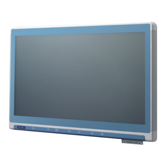
- Page 1 User Manual POC-W181 Intel® i7 Processor 2610UE Point of Care Terminal with 18.5” TFT LCD...
- Page 2 Note! A NOTE provides additional information intended to avoid inconve- niences during operation. Part No. 2008018110 Edition 1 Printed in Taiwan July 2012 POC-W181 User Manual...
- Page 3 WARNINGS and CAUTIONS as rendered throughout this manual and on labels on the equipment. Repair of the device may only be carried out by trained service personnel. Advantech recommends that a service contract be obtained with Advantech Service and that all repairs also be carried out by them.
- Page 4 Caution! When servicing the device, always use replacement parts that are quali- fied to Advantech standards. Advantech Medical cannot warrant or endorse the safe performance of third-party replacement parts for use with our medical devices.
- Page 5 Grounding reliability can only be achieved when the equipment is connected to an equivalent receptacle marked “Hospital Only” or “Hospital Grade”. Use a power cord that matches the voltage of the power outlet, which has been approved and complies with the safety standard of your particular country. POC-W181 User Manual...
- Page 6 The mark on electrical and electronic products only applies to the current European Union member states. POC-W181 User Manual...
- Page 7 Guidance and manufacturer’s declaration - electromagnetic emissions Model POC-W181 is intended for use in the electromagnetic environment specified below. The customer or the user of the model POC-W181 should assure that it is used in such an environment. Emissions test...
- Page 8 Guidance and manufacturer’s declaration - electromagnetic immunity Model POC-W181 is intended for use in the electromagnetic environment specified below. The customer or the user of the model POC-W181 should assure that it is used in such an environ- ment. IEC 60601 test...
- Page 9 Guidance and manufacturer’s declaration - electromagnetic immunity Model POC-W181 is intended for use in the electromagnetic environment specified below. The customer or the user of the model POC-W181 should assure that it is used in such an environ- ment. IEC 60601 test...
- Page 10 Accordingly it is strongly recommended that only these accessories be used in conjunc- tion with the specific device. Otherwise the correct functioning of the device may be compromised. POC-W181 User Manual...
- Page 11 Additional Information and Assistance Contact your distributor, sales representative, or Advantech's customer service cen- ter for technical support if you need additional assistance. Please have the following information ready before you call: Product name and serial number Description of your peripheral attachments ...
- Page 12 POC-W181 User Manual...
-
Page 13: Table Of Contents
Connecting the Power Cord............11 Figure 2.6 Connecting the Power Cord ........11 2.2.2 Connecting the Ground Pin............12 Figure 2.7 POC-W181 Equipotential Terminal Pin ....12 Figure 2.8 Grounding Cable with Connector ......12 2.2.3 Switch on the Power ..............13 Figure 2.9 Press the Power Button to Boot System .... - Page 14 Figure 6.1 PCM-8712 MB Top ..........24 Figure 6.2 PCM-8712 MB Bottom ..........24 Chapter Front Bezel Button......29 Introduction ..................... 30 Chapter POC-W181 Advanced BIOS Functions Introduction ..................... 32 POC-W181 User Manual...
-
Page 15: Chapter 1 General Information
Chapter General Information... -
Page 16: Introduction
With a 2.5” SATA HDD drive optional, the POC-W181 is an user-friendly computer. For system integrators, this highly integrated multimedia system lets you easily build a Point of Care Terminal into your applications. The POC-W181 makes it an ideal and safe point of care solution for patients and hospital practitioners. - Page 17 375 mmHg to 760 mmHg(Transportation) Water/Dust IPX1 compliant Resistance Dimensions 454 x 304 x56 mm (17.87" x 11.96" x 2.21") Physical (W x H x D) Characteristics Weight 5.8 kg Platform & Utilities XP Professional, Windows 7, SUSI POC-W181 User Manual...
- Page 18 Unit: mm DCIN Figure 1.1 Dimensions VESA Mounting: 75 x 75 mm; 100 x 100 mm Figure 1.2 VESA Mounting POC-W181 User Manual...
- Page 19 Incidin plus Incidin liquid Mikrozid liquid Caution! Do not immerse or rinse the POC-W181 or its peripherals. If you acci- dentally spill liquid on the device, disconnect the unit from the power source. Contact your Biomed department regarding the continued safety of the unit before placing it back in operation.
- Page 20 POC-W181 User Manual...
-
Page 21: Chapter 2 System Setup
Chapter System Setup... -
Page 22: A Quick Tour Of The Poc-W181
A Quick Tour of the POC-W181 Before you start to set up the POC-W181, take a moment to become familiar with the locations and purposes of the controls, drives, connections and ports, which are illus- trated in the figures below. -
Page 23: Rear View
3 and Figure 2-4. (The I/O section includes various I/O ports, including serial ports, DVI port, the Ethernet port, USB ports and so on.) Figure 2.2 Rear View of the Point of Care Terminal Figure 2.3 Rear View of Multi I/O Ports-1 POC-W181 User Manual... -
Page 24: Bottom View
Gigabit Ethernet (network) ports labeled TCP/IP (LAN1) COM 1 port COM 2 port Dove tail Equipotential terminal USB x2 ports USB x2 ports Dove tail 2.1.3 Bottom View Figure 2.5 Bottom View Smart card reader (option) Speaker x 2 POC-W181 User Manual... -
Page 25: Installation Procedures
Installation Procedures 2.2.1 Connecting the Power Cord The POC-W181 can only be powered by DC power adapter SINPRO Model no# HPU100-107. Be sure to always handle the power cords by holding the plug ends only. Follow these procedures in order: Connect the female end of the power adapter to the DC jack of the panel PC. -
Page 26: Connecting The Ground Pin
Figure 2.7 POC-W181 Equipotential Terminal Pin Step 2.Prepare the Grounding cable and the other terminal link to hospital ground/ earth system. Figure 2.8 Grounding Cable with Connector Step 3.Grounding cable plug with POC-W181 Equipotential Terminal (See Figure 2- POC-W181 User Manual... -
Page 27: Switch On The Power
Figure 2.9 Press the Power Button to Boot System Running the BIOS Setup Program Your POC-W181 has been properly set up and configured by your dealer prior to delivery. You may still find it necessary to use the BIOS (Basic Input-Output System) setup program to change system configuration information, such as the current date and time or your type of hard drive. -
Page 28: Installing The Drivers
For your reference, the directory of drivers on the "Drivers and Utilities" DVD “d:\driver” folder. Note! The drivers and utilities used for the POC-W181 panel PCs are subject to change without notice. If in doubt, check Advantech's website or con- tact our application engineers for the latest information regarding drivers and utilities. - Page 29 These Windows 7 drivers are all 32-bit version. Note! The drivers and utilities used for the POC-W181 panel PCs are subject to change without notice. If in doubt, check Advantech's website or con- tact our application engineers for the latest information regarding drivers and utilities.
-
Page 30: Troubleshooting
Power LED ON but no DC power output AC power in and all switches ON, but system doesn't power on Contact your distributor, sales representative, or Advantech's customer service cen- ter for technical support if you need additional assistance. Please have the following information ready before you call: ... -
Page 31: Chapter 3 Driver Installation
Chapter Driver Installation... -
Page 32: Introduction
Introduction The POC-W181 supports “one key” driver installation. User can click one button to install all drivers. Warning! Please use clean OS to perform this auto installation, otherwise, it might cause un-expect error. Automatic Driver Installation Windows XP (32-Bit) Step 1.Double Click “setup.exe”... -
Page 33: Chapter 4 Utilities And Hot Fixes
Chapter Utilities and Hot fixes... -
Page 34: Introduction
Introduction The POC-W181 system needs specific utilities or hot fixes to support special func- tions. Wakeup by External USB Device at S3 Resume (Wakeup) POC-W181 supports three different sleep (suspend) modes, they are: S1: Power On Suspend, system will stop the clock, turn off LCD backlight, but keep all power on. -
Page 35: Chapter 5 Operation And Safety Information
Chapter Operation and Safety information... -
Page 36: General Safety Guide
Thermal The vent hole of the POC-W181 rear cover functions as a cooling air flow inlet and outlet. These air inlets and outlets transfer heat from inside the computer to the cooler air outside. Do not block these holes/vents by any soft material. -
Page 37: Chapter 6 Pcm-8712 Connector Map And Table
Chapter PCM-8712 Connector Map and Table... - Page 38 Figure 6.1 PCM-8712 MB Top Figure 6.2 PCM-8712 MB Bottom POC-W181 User Manual...
- Page 39 Panel Type Selection CN65 Back-up Battery Signal Connector CN30 Touch Sensor Connector CN17 SATA HDD Signal Connector CN18 SATA HDD Power Connector CN36 Front Button Board Connector (POC-Cart) System Reset Connector CN45 Touch Sensor Enable Connector (Reserved) POC-W181 User Manual...
- Page 40 COM1 RS232/422/485 output type setting Clear CMOS Description Clear CMOS Setup Setting Function (1-2) Clear CMOS Setup (No Connect) Normal Operation (Default) Clear ME Description Clear ME Setup Setting Function (1-2) Clear ME Setup (No Connect) Normal Operation (Default) POC-W181 User Manual...
- Page 41 Select boot main display setting Setting Function Set VGA as main display at bootup Set LVDS as main display at bootup ME Manufacturing Mode Description ME Manufacturing Mode Setting Function (1-2) ME Manufacturing Mode (No Connect) Normal Operation (Default) POC-W181 User Manual...
- Page 42 System Reset Description System Reset Setting Function (1-2) System Reset (No Connect) Normal Operation (Default) COM-1 Jumper setting RS-232 RS-422 RS-485 RS-485: 2 Wires type RS-422: 4 Wires type POC-W181 User Manual...
- Page 43 Chapter Front Bezel Button...
- Page 44 LCD backlight will be turned off. And pressing both buttons for half a second again will turn on the LCD backlight. When backlight is off, the POC-W181 system is still running. The backlight does not impact any programs operating.
- Page 45 Chapter POC-W181 Advanced BIOS Functions...
- Page 46 Introduction This section Introduces the advanced functions in the POC-W181 BIOS menu. Power Button Function Enable/Disable You can enable/disable power button function in BIOS menu. If you disable the power button in S0 (System ON) status, the power button will not work.
- Page 47 BIOS Menu location: BIOS Menu - Boot - Setup Popup Menu F12 Enable: Press F12 key at bootup displays popup menu (Default) Disable: Press F12 key at bootup does not display popup menu POC-W181 User Manual...
- Page 48 No part of this publication may be reproduced in any form or by any means, electronic, photocopying, recording or otherwise, without prior written permis- sion of the publisher. All brand and product names are trademarks or registered trademarks of their respective companies. © Advantech Co., Ltd. 2012...
Need help?
Do you have a question about the POC-W181 and is the answer not in the manual?
Questions and answers