
Subscribe to Our Youtube Channel
Related Manuals for Advantech PPC-6150


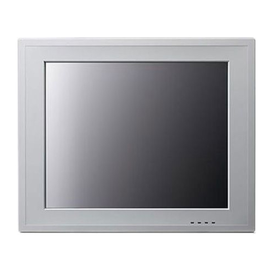
Summary of Contents for Advantech PPC-6150
- Page 1 User Manual PPC-6150/6170 Intel® Core i3,i5/Celeron 1020E processor based microcomputer, with 15"/17" color TFT LCD display...
- Page 2 No part of this manual may be reproduced, copied, translated or transmitted in any form or by any means without the prior written permission of Advantech Co., Ltd. Information provided in this manual is intended to be accurate and reliable. How- ever, Advantech Co., Ltd.
-
Page 3: Declaration Of Conformity
This product has passed the CE test for environmental specifications when shielded cables are used for external wiring. We recommend the use of shielded cables. This kind of cable is available from Advantech. Please contact your local supplier for ordering information. -
Page 4: Safety Instructions
The sound pressure level at the operator's position according to IEC 704-1:1982 is no more than 70 dB (A). DISCLAIMER: This set of instructions is given according to IEC 704-1. Advantech disclaims all responsibility for the accuracy of any statements contained herein. - Page 5 Disconnect power before making any configuration changes. The sudden rush of power as you connect a jumper or install a card may damage sensitive elec- tronic components. Power Warning The power is only fit for areas with an altitude of below 5000 Meters. PPC-6150/6170 User Manual...
- Page 6 PPC-6150/6170 User Manual...
- Page 7 Chapter General Information This chapter gives background information on PPC-6150/6170 panel PC. Sections include: Introduction Specifications Dimensions...
-
Page 8: Introduction
Introduction Advantech PPC-6150/6170 are Intel Core i3/i5 processor based panel PCs with 15" and 17" color LCD respectively. They feature powerful computing capability, modular design and excellent connection performance, fit for almost any application. In addi- tion, their user friendly interface makes it easy to operate. For example, they have two expansion slots, dual HDDs, Intel RAID support, and an isolated RS-232/422 / 485 port. -
Page 9: General Specifications
55 W (test system: Windows7 32bit) Power (i3-3210ME) 47 W (test system: Windows XP 32bit) 47 W (test system: Windows XP 32bit) Output Power 150 W (Max.) Input Voltage 100-240 Vac, 50/60 Hz, 4 A ~ 2 A PPC-6150/6170 User Manual... -
Page 10: Certification Specifications
10 ~ 95% @ 40°C (non-condensing) Shock 10 G peak acceleration (11 msec duration) Vibration 5 ~ 500 Hz 1 G RMS 1.2.6 Certification Specifications BSMI, CE, FCC Class A Safety CB, CCC, BSMI, UL 1.2.7 IP Front Panel IP Grade IP65 PPC-6150/6170 User Manual... -
Page 11: Chapter 1 General Information
7 32bit IO: COM Port RS232 loopback i3-3120ME @2.4 GHz Windows x5: USB3.0 device x5 XP 32bit Note2: PPC-6150's power test conditions are as follows (for reference only, powers differ from different peripheral configurations) Test Test Power Test Configuration Software... - Page 12 Dimensions PPC-6150: Unit: mm Figure 1.1 PPC-6150 dimensions Fixed VESA screw specification: M4; screw depth: 7.5 mm (Max). Warning! Use suitable mounting apparatus to avoid the risk of injury. PPC-6150/6170 User Manual...
- Page 13 PPC-6170: Figure 1.2 PPC-6170 dimensions Fixed VESA screw specification: M4; screw depth: 7.5 mm (Max). Warning! Use suitable mounting apparatus to avoid the risk of injury. PPC-6150/6170 User Manual...
-
Page 14: Touchscreen Specifications
PPC-6150/6170 User Manual... -
Page 15: Table Of Contents
Environment Specifications............4 1.2.6 Certification Specifications............4 1.2.7 IP ....................4 Dimensions ....................6 Figure 1.1 PPC-6150 dimensions..........6 Figure 1.2 PPC-6170 dimensions..........7 Chapter System Installation & Setup ....9 Quick Start Guide..................10 Figure 2.1 Front panel ............... 10 Figure 2.2 Side view .............. -
Page 16: Dimensions
RAID Function Configuration ............52 4.2.8 PCIE/RI Wakeup................. 53 Appendix A PCI/PCIE (Images) & Dual HDD RAID Function Configuration59 PCI/PCIE (Images) ................. 60 Dual HDD RAID ..................61 A.2.1 Windows XP Dual HDD RAID System Installation Procedures .. 61 PPC-6150/6170 User Manual viii... - Page 17 A.2.2 Windows 7 Dual HDD RAID System Installation Procedures ..67 PPC-6150/6170 User Manual...
- Page 18 PPC-6150/6170 User Manual...
-
Page 19: Chapter 2 System Installation & Setup
Chapter System Installation & Setup Sections include: Quick Installation Guide HDMI Specifications Install Memory Install ODD Install HDD Install MINI SATA and Wireless LAN Card Install Riser Card Panel Mount Bracket Installation ... -
Page 20: Quick Start Guide
Figure 2.1 Front panel Light sense LAN LED HDD LED POWER LED LAN LED Status HDD LED POWER LED LAN1 LAN2 Power Off (S5) Off Yellow Green Yellow Yellow Power On (S0) Green (working, blink) (working, blink) (working, blink) PPC-6150/6170 User Manual... -
Page 21: Figure 2.2 Side View
Figure 2.2 Side view Air outlet Antenna hole Panel Mount Bracket hole (10 in PPC-6170, 8 in PPC-6150) Slim type optical drive bay Loudspeaker (dual) Air inlet Note! Fixed VESA specification: M4; screw depth: 7.5 mm (Max). PPC-6150/6170 User Manual... -
Page 22: Figure 2.3 Location Of I/O Interfaces
K: DIO / COM5 port (by swapping pin header) K1: COM1(RS232,Pin9 supports 5 V/12 V output) K2: COM2(RS232/422/485,with isolation) K3: COM3(RS232,Pin9 supports 5 V/12 V output) K4: COM4(RS232) Note! Wire clasp dimension: 9 mm x 3.5 mm. PPC-6150/6170 User Manual... -
Page 23: Hdmi Standard
9mm long, or an imperfect contact may happen. Length: above 9mm Figure 2.4 Keep same direction (groove side) between HDMI cable and PPC-61X0 HDMI connector. Figure 2.5 Insert the HDMI cable with groove side downward. Figure 2.6 PPC-6150/6170 User Manual... -
Page 24: Figure 2.7
Insert HDMI cable close to the right of the side. Figure 2.7 Align the HDMI Cable with HDMI connector and insert smoothly. Note! If it can't be inserted smoothly, don't use force. Adjust the HDMI cable and insert again. Figure 2.8 PPC-6150/6170 User Manual... -
Page 25: Install Memory Card
Install Memory Card Remove the rear cover of the panel PC. (See Fig 2.9) Figure 2.9 After removing rear cover Remove the two screws of the riser card (see Fig 2.10), and pull it out. Figure 2.10 PPC-6150/6170 User Manual... -
Page 26: Figure 2.11
(see Fig 2.11) and the one in I/O stop plate. Figure 2.11 Remove the reinforced board. (see Fig 2.12) Figure 2.12 Remove CPU fan cable and the four screws of the CPU cooler and remove it. Figure 2.13 PPC-6150/6170 User Manual... -
Page 27: Install Odd
QM77 and memory and place them in the correct locations (see Fig 2.14), then install the CPU cooler to complete the memory installation. Figure 2.14 Install ODD Remove the four screws as shown in Fig 2.15, and take out the HDD2 bracket. Figure 2.15 PPC-6150/6170 User Manual... -
Page 28: Install Hdd
Fig 2.16) Figure 2.16 Install HDD 2.5.1 Install HDD1: Please follow procedures 1~ 4 in Section 2.3. Remove the four screws as indicated below, and then take down the U-type HDD bracket. (See Fig 2.17) Figure 2.17 PPC-6150/6170 User Manual... -
Page 29: Figure 2.18
4 x M3X4), and insert HDD cable into HDD module. (See Fig 2.18) Figure 2.18 Return to the original position, then connect HDD cable to the mainboard. (See Fig 2.19) Figure 2.19 PPC-6150/6170 User Manual... -
Page 30: Install Hdd2
Take out the U type bracket, four black washers, four screws. (See Fig 2.20) Figure 2.20 Position the four washers as shown in Fig 2.21. Then take out four M3 screws from the accessory box and secure the HDD onto the U-type cradle. Figure 2.21 PPC-6150/6170 User Manual... -
Page 31: Figure 2.22
Connect HDD cables. (See Fig 2.22) Figure 2.22 Complete the installation of HDD. (See Fig 2.23) Figure 2.23 PPC-6150/6170 User Manual... -
Page 32: Install Mini Sata And Wireless Network Card
(The following installation procedures are only for professional technician’s’ refer- ence. The screws needed in this process can be found in the accessory box. Follow the procedures in Section 2.3. Untie the USB cable, and remove the cable and two screws in MIO mainboard. Figure 2.24 PPC-6150/6170 User Manual... -
Page 33: Figure 2.25
Unplug the cables beside the IO as shown below, and remove the two hexago- nal screws in VGA of I/O back plate. Then lift out the MIO board. (See Fig 2.25) Figure 2.25 PPC-6150/6170 User Manual... -
Page 34: Install Mini Sata
Mini SATA by BIOS, refer to the “BIOS Configu- ration” chapter for the details. Figure 2.26 2.6.2 Install Wireless LAN Long Card First remove the wireless LAN card antenna bracket. (See Fig 2.27) Figure 2.27 PPC-6150/6170 User Manual... -
Page 35: Figure 2.28
Fix the antenna onto the bracket. (See Fig 2.28) Figure 2.28 Secure the bracket with the antenna onto M/B frame, the wiring method is shown in Fig 2.29. The antenna receiver is secured onto the antenna terminal. (See Fig 2.30) Figure 2.29 PPC-6150/6170 User Manual... -
Page 36: Figure 2.30
LAN card into the MIO-5290 CN28 slot. Note! Long card and MiNi SATA slot share one slot. Users need to configure the port as PCIE by BIOS, please refer to “BIOS Configuration” chapter for the details. Figure 2.31 PPC-6150/6170 User Manual... -
Page 37: Install The Wireless Lan Short Card
Follow the procedures in Section 2.6.2, and install the antenna to the machine. Take out one M2 X 6 screws from the accessory box, and lock the short card into MIO-5290 CN29 card slot. (See Fig 2.33) Figure 2.33 PPC-6150/6170 User Manual... -
Page 38: Figure 2.34
Reinstall the MIO mainboard, lock the screws and return the cables according to Procedure 3-6. Check all cables are correctly connected, as shown in Figures 2.35, 2.36 and 2.37 respectively. Lock the cooler onto MIO mainboard and connect the MIO fan cable. (See Fig 2.35) Figure 2.35 PPC-6150/6170 User Manual... -
Page 39: Figure 2.36
Lock the reinforced board and connect the fan cable, and check the left system fan cable is connected correctly. (See Fig 2.37) Figure 2.37 Lock the reinforced board, riser card and rear cover to complete the installation. PPC-6150/6170 User Manual... -
Page 40: Installing The Riser Card
Insert the riser card into the slot, and lock the two screws.(See Figure 2.38) Figure 2.38 Remove the card slot back plate, and insert the needed card (See Fig 2.39), then fix the screws and return the rear cover. Figure 2.39 PPC-6150/6170 User Manual... -
Page 41: Panel Mount Bracket Installation
Panel Mount Bracket Installation Follow the figures below: Panel Panel Figure 2.40 PPC-6150/6170 User Manual... -
Page 42: Power Cable Bracket Installation
Lock the power cable bracket onto the machine using two M3X5 screws as shown in the figure below. Figure 2.42 When using the power bracket, select the power cable with correct connecter. The dimension of the bracket is shown below: PPC-6150/6170 User Manual... -
Page 43: Jumper Configuration
Chapter Jumper Configuration Sections include: Jumpers & Connectors Peripheral COM Port & DIO Switch and Pin Definitions Peripheral DIO and COM5 Port Switch Touchscreen Control Source Configuration... -
Page 44: Jumpers & Connectors
USB for touch CN10 Light sense CN59 COM5 (RS232, default for Touch) CN12 CN13 LCD size select CN17 Touch CN18 LPT Port CN21 Speaker CN20 Audio CN19 Pin9 power select (COM1&COM3) JP1&JP2 Touch source select PPCIE1 PCIEx4 (non standard) PPC-6150/6170 User Manual... - Page 45 JP1 (7-11), JP1 (8-12) P8 (Default) COM5 control JP2 (1-5), JP2 (2-6) JP2 (3-7), JP2 (4-8) JP1(1-5), JP1 (2-6) JP1 (3-7), JP1 (4-8) USB control JP2(5-9), JP2 (6-10) JP2(7-11), JP1 (8-12) COM Port (default) USB interface Image P8 Image P9 PPC-6150/6170 User Manual...
-
Page 46: Mio-5290
3.1.2 MIO-5290 Figure 3.2 MIO-5290 front view Bottom Figure 3.3 MIO-5290 rear view PPC-6150/6170 User Manual... - Page 47 Clear CMOS Image P10 Image P11 Images For ATX & AT Select Configuration Functions On(1-2) AT mode OFF(1-2) ATX mode (Default) Image P12 Image P13 Images For LVDS Power Select Configuration Functions (1-3) 15”LCD mode (3-5) 17”LCD mode PPC-6150/6170 User Manual...
-
Page 48: External Com Port & Dio Switch And Pin Definition
(Open the rear cover before configuration) Figure 3.4 COM ports K: DIO / COM5 port (by swapping pin header) K1: COM1(RS232, pin9 supports 5 V/12 V output) K2: COM2(RS232/422/485, with isolation) K3: COM3(RS232, pin9 supports 5 V/12 V output) K4: COM4 (RS232) PPC-6150/6170 User Manual... - Page 49 8 bit parallel input and output port. Control signal is SMBUS. External COM PORT & DIO PIN definition: Ports Functions RS232 RS422 RS485 422_TXD- 485_Data- 422_TXD+ 485_Data+ GPIO4 422_RXD+ GPIO0 422_RXD- GPIO5 GPIO1 GPIO6 GPIO2 GPIO7 GPIO3 PPC-6150/6170 User Manual...
-
Page 50: External Port Dio And Com5 Switch
External Port DIO and COM5 Switch Configure the external port as DIO (default). Figure 3.5 PPC-6150/6170 User Manual... -
Page 51: Figure 3.6
Configure JP1 and JP2 as shown in Fig 3.6. (This configuration will change touchscreen's control source as USB, and the system needs to reinstall touch- screen driver.) Figure 3.6 b. Connect the cable to COM5. (See Fig 3.7) Figure 3.7 PPC-6150/6170 User Manual... -
Page 52: Touchscreen Control Source Configuration
Take down DIO cable, and configure JP&JP2 as shown in Fig 3.8, then insert the DIO cable. Figure 3.8 Use the USB to control the touchscreen. Remove the DIO cable, and configure JP&JP2 as shown in the figure below, then reattach the DIO cable. Figure 3.9 PPC-6150/6170 User Manual... -
Page 53: Software Configuration
Chapter Software Configuration Sections include: Driver Installation BIOS Setup Program... -
Page 54: Driver Installation
User manual: E-record of the user manual for this machine. Follow the instructions to install the drivers. The drivers in the accompanied CD-ROM may not be the latest version, if needed, find it at: http://www.advantech.com.cn/ PPC-6150/6170 User Manual... -
Page 55: Bios Setup
BIOS Setup 4.2.1 Enter BIOS Start the computer and press “Delete” key to enter BIOS. Press “F4” to save and exit after any configuration, or the configuration won't be saved in the BIOS. PPC-6150/6170 User Manual... -
Page 56: Atx & At Mode Setup
4.2.2 ATX & AT Mode Setup Select “PCH-IO Configuration” under “Chipset”. Configure “Restore AC Power Loss” as “Power On”. PPC-6150/6170 User Manual... -
Page 57: Display Brightness Adjustment
4.2.3 Display Brightness Adjustment Select “Chipset” under “Brightness Control”. A.Manual Adjustment Mode “LCD Brightness Control” is configured as “Manual Mode” by default. Select “Brightness Manual Control” under “Brightness Control”, and there will be six options: PPC-6150/6170 User Manual... -
Page 58: Com 232/422/485 Port
B. Auto Sensor Adjustment Mode “LCD Brightness Control” is configured as “Dynamic Mode”, that is, auto sensor adjustment mode. Then the machine will automatically adjust the LCD brightness from sensor points. 4.2.4 COM 232/422/485 Port Select “Advanced” under “Super IO Configuration”. PPC-6150/6170 User Manual... - Page 59 Then Select “Serial Port 2 Configuration”. Then you can select the operation mode of COM2 by “Serial Port2 Mode”. PPC-6150/6170 User Manual...
-
Page 60: Minipcie & Minisata Configuration Method
4.2.5 MiniPCIE & MiniSATA Configuration Method Select “Chipset” under “PCH-IO Configuration”. Then select “MINI Card/M-SATA”. PPC-6150/6170 User Manual... -
Page 61: Pcie Mode Select (X1, X4)
Enter and select MINI PCIE type. Mini Card: CN28 is of Mini PCIE interface. M-SATA: CN28 is of Mini SATA interface. 4.2.6 PCIE Mode Select (x1, x4) Select “Chipset” under “PCIE Port Configuration”. PPC-6150/6170 User Manual... -
Page 62: Raid Function Configuration
PCIE X1: PPCIEX1 interface includes 4 PCIEx1 interface. (Users need to set this mode when using PCM-917/918/920) PCIE X4: PPCIEX1 interface includes 1 PCIEx4 interface. (Users need to set this mode when using PCM-916) 4.2.7 RAID Function Configuration Select “SATA Configuration” under “Advanced”. PPC-6150/6170 User Manual... -
Page 63: Pcie/Ri Wakeup
Then select “RAID” in “SATA Mode Selection”. 4.2.8 PCIE/RI Wakeup Select “Chipset” under “PCH-IO Configuration”. PPC-6150/6170 User Manual... - Page 64 Select “Wake on PCIE/RI” as “Enabled” under “PCH-IO Configuration”. Open wake on LAN function in the system. A. Open wake on LAN function in windows 7. Right click “Computer” and select “Manage” to enter management interface, then select “Device Manager”. PPC-6150/6170 User Manual...
- Page 65 Select “Network adapters”, and two network devices will appear. Select any device with wake on LAN function, and right click to select “Properties”. Select “Power Management”, and remember to check “Wake on Magic Packet” and “Wake on Magic Packet from power off state”. PPC-6150/6170 User Manual...
- Page 66 B. Open wake on LAN function in windows XP. Right click “Computer” and select “Manage” to enter management interface, then select “Network adapters”, and 2 network devices will appear. Select any device with wake on LAN function, and right click to select “Properties”. PPC-6150/6170 User Manual...
- Page 67 Select “Power Management”, and remember to check “Wake on Magic Packet” and “Wake on Magic Packet from power off state”. PPC-6150/6170 User Manual...
- Page 68 PPC-6150/6170 User Manual...
- Page 69 Appendix PCI/PCIE (Images) & Dual HDD RAID Function Configuration...
-
Page 70: Pci/Pcie (Images)
PCI/PCIE (Images) PCM-916 1-PCIEX4 slot (in the accessory box) PCM-917 2-PCIEX1 slots (optional) PCM-918 2-PCI32 slots (optional) PCM-920 1-PCIEX1&1-PCI32 slot (default) PPC-6150/6170 User Manual... -
Page 71: Dual Hdd Raid
Total output voltage of 12 V, 5 V and 3.3 V can not exceed 25 W. Dual HDD RAID A.2.1 Windows XP Dual HDD RAID System Installation Procedures Enter BIOS and set SATA mode as RAID. Please press “Ctrl+I” to enter RAID screen during bootup. PPC-6150/6170 User Manual... - Page 72 Select “Create RAID Volume” to create RAID. Users can choose RAID0 or RAID1 mode here. Select “Create Volume” after mode configuration, and you’ll be reminded that RAID HDD data will be erased. Press “Y” to confirm selecting RAID mode. PPC-6150/6170 User Manual...
- Page 73 Select “Exit” and press “Y” to exit the screen. Then it will boot from CD-ROM. Press “F6” to wait loading RAID driver. PPC-6150/6170 User Manual...
- Page 74 You can press “S” to select the driver when “loading driver” appears. Select “Intel (R) Mobile Express Chipset SATA RAID Controller” and press “Enter” to continue. PPC-6150/6170 User Manual...
- Page 75 Press “Enter” to continue. Press “Enter” to prepare installing system. PPC-6150/6170 User Manual...
- Page 76 Press “F8” to agree starting installation. It will appear the total HDD size after RAID configuration, then you can create partition. PPC-6150/6170 User Manual...
- Page 77 XP. Users need to configure dual HDD as RAID mode and then start installation. It will continue introducing from the above step 5 here. Continue with Step 5, boot from CD-ROM, and continue installation according to the instructions. It will appear the HDDs with RAID successfully configured. PPC-6150/6170 User Manual...
- Page 78 You can create partition by your favorite and continue installation. Click “Next” to continue and complete the installation. PPC-6150/6170 User Manual...
- Page 79 PPC-6150/6170 User Manual...
- Page 80 No part of this publication may be reproduced in any form or by any means, electronic, photocopying, recording or otherwise, without prior written permis- sion of the publisher. All brand and product names are trademarks or registered trademarks of their respective companies. © Advantech Co., Ltd. 2016...
Need help?
Do you have a question about the PPC-6150 and is the answer not in the manual?
Questions and answers