Table of Contents
Advertisement
Quick Links
Advertisement
Table of Contents

Related Manuals for Yamaha O1V96


Summary of Contents for Yamaha O1V96
- Page 1 Owner’s Manual Keep This Manual For Future Reference.
- Page 2 Yamaha Corporation of America or its subsidiaries. of other electronic devices. Compliance with FCC regulations does * This applies only to products distributed by YAMAHA CORPORATION OF AMERICA. (class B) ADVARSEL! IMPORTANT NOTICE FOR THE UNITED KINGDOM Lithiumbatteri—Eksplosionsfare ved fejlagtig håndtering.
-
Page 3: Important Safety Instructions
• Explanation of Graphical Symbols The lightning flash with arrowhead symbol within an equilateral triangle is intended to CA UT I O N alert the user to the presence of uninsulated RISK OF ELECTRIC SHOCK “dangerous voltage” within the product’s DO NOT OPEN enclosure that may be of sufficient magnitude to constitute a risk of electric shock to persons. - Page 4 Yamaha service personnel. inspected by qualified Yamaha service personnel. CAUTION Always follow the basic precautions listed below to avoid the possibility of physical injury to you or others, or damage to the device or other property.
-
Page 5: Backup Battery
Insert TRS phone jacks are wired as follows: sleeve: ground, tip: send, and ring: return. Yamaha cannot be held responsible for damage caused by improper use or modifications to the device, or data that is lost or destroyed. Always turn the power off when the device is not in use. -
Page 6: Package Contents
Yamaha Pro Audio global website Yamaha Pro Audio global website http://www.yamahaproaudio.com/ Package Contents • 01V96 Digital Mixing Console • CD-ROM • Power cord • This manual • Studio Manager Installation Guide Optional Extras • RK1 Rack Mount Kit • mini YGDAI I/O cards About this Owner’s Manual... -
Page 7: Aux Sends
• • Yamaha’s proprietary Advanced DAW protocol has been added to Nuendo, Cubase SX, and General DAW. This enables you to control these devices using the 01V96’s SELECTED CHANNEL section. (Controllable functions vary depending on the DAW software and ver- sion you are using.) -
Page 8: Table Of Contents
Contents Contents Welcome ........11 Control Surface &... - Page 9 Contents Setting Aux Send Levels ..........113 Viewing Aux Send Settings for Multiple Channels .
- Page 10 Contents 18 MIDI ......... . . 215 MIDI &...
-
Page 11: Welcome
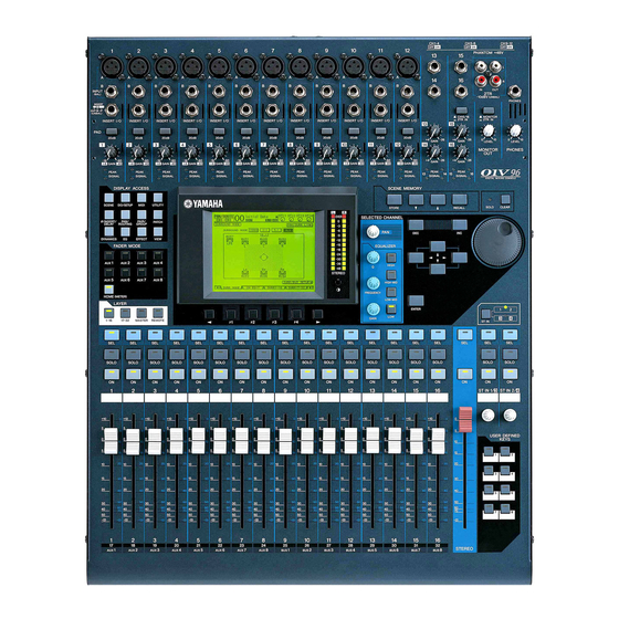
Welcome 1 Welcome Thank you for choosing the Yamaha 01V96 Digital Mixing Console. The compact 01V96 Digital Console features 24-bit/96 kHz digital audio processing with- out compromise, as well as 40-channel simultaneous mixing. The 01V96 covers a broad range of needs and applications, including multi-track recording, 2-channel mixdown, and cutting-edge surround sound production. -
Page 12: Surround Sound
Chapter 1—Welcome ■ Channel Configuration • 32 Input Channels and four ST IN channels can be mixed at a time. Group multiple channels and pair channels for stereo. • Eight Bus Outs and eight Aux Sends. Bus Outs 1-8 can be routed to Stereo Buses for use as Group Buses. -
Page 13: Control Surface & Rear Panel
Yamaha does not sell such a cover. If you fabricate and attach your own cover, make sure that the mounting screws do not extend more than 10 mm into the front panel. -
Page 14: Ad Input Section
Chapter 2—Control Surface & Rear Panel AD Input Section CH1-4 INPUT (BAL) INSERT OUT IN (UNBAL) CH15/16 2TR IN INSERT I/O INSERT I/O INSERT I/O INSERT I/O INSERT I/O INSERT I/O INSERT I/O INSERT I/O INSERT I/O 20dB 20dB 20dB 20dB 20dB 20dB... -
Page 15: Monitor Source Selector
Control Surface D PAD switches These switches turn on or off the 20 dB pad (attenuator) for each AD Input. E GAIN controls These controls adjust input sensitivity for each AD Input. Input sensitivity is –16 dB to –60 dB when the Pad is off, and +4 dB to –40 dB when the Pad is on. F PEAK indicators These indicators light up when the input signal level is 3 dB below clipping. -
Page 16: Channel Strip Section
Chapter 2—Control Surface & Rear Panel Channel Strip Section A [SEL] buttons These buttons enable you to select desired channels. The [SEL] button indicator for the cur- rently-selected channel lights up. The channel selected by each [SEL] button depends on the layer selected in the LAYER section (see page 19). -
Page 17: Level Controls
Control Surface ST IN Section ST IN SOLO SOLO ST IN 1 ST IN 2 A [ST IN] button This button selects an ST IN channel pair (ST IN Channels 1 & 2 or 3 & 4) which you can control using the buttons and controls in the ST IN section. -
Page 18: Display Access Section
Chapter 2—Control Surface & Rear Panel DISPLAY ACCESS Section 1 2 3 DISPLAY ACCESS SCENE SCENE DIO/SETUP DIO/SETUP MIDI MIDI UTILITY UTILITY / INSERT/ PAN/ PAIR/ PATCH ROUTING GROUP DELAY EFFECT VIEW DYNAMICS 9 J K L A [SCENE] button This button displays a Scene page, enabling you to store and recall Scenes (see page 165). -
Page 19: Layer Section
Control Surface LAYER Section LAYER 1-16 17-32 MASTER REMOTE A [1–16]/[17–32] buttons These buttons select an Input Channel layer as the layer controlled in the Channel Strip sec- tion. When the [1–16] button is turned on, you can control Channels 1–16. When the [17–32] button is turned on, you can control Channels 17–32. -
Page 20: Selected Channel Section
Chapter 2—Control Surface & Rear Panel E Left Tab Scroll [ ] button F Right Tab Scroll [ ] button If there are more pages available than the four whose tabs are currently displayed, use these buttons to display the additional tabs. These buttons are available only when the left or right Tab Scroll arrow appears. -
Page 21: Scene Memory Section
Control Surface SCENE MEMORY Section SCENE MEMORY STORE RECALL A [STORE] button This button enables you to store the current mix settings. (See page 165 for more informa- tion on Scene Memories.) B Scene Up [ ] / Down [ ] buttons These buttons select a Scene to store or recall. -
Page 22: Data Entry Section
Chapter 2—Control Surface & Rear Panel Data Entry Section ENTER A Parameter wheel This control adjusts the parameter values shown on the display. Turning it clockwise increases the value; turning it counterclockwise decreases the value. This wheel also enables you to scroll a displayed list and select a character for entry (see page 30). B [ENTER] button This button activates a selected (highlighted) button on the display, and confirms the edited parameter values. -
Page 23: Rear Panel
Rear Panel Rear Panel PHANTOM +48V (p. 23) AD Output Section Digital I/O Section MIDI/Control Section (p. 23) (p. 24) (p. 25) Power Section (p. 25) SLOT Section (p. 25) PHANTOM +48V A CH1–4 ON/OFF switch B CH5–8 ON/OFF switch C CH9–12 ON/OFF switch Each of these switches turns on or off the +48V phantom power feed to four corresponding inputs. -
Page 24: Digital I/O Section
Chapter 2—Control Surface & Rear Panel B OMNI OUT connectors 1–4 Tip (hot) These balanced TRS phone-type con- Ring nectors output any Bus signals or 1/4" TRS phone plug (cold) channel Direct Out signals. The nom- inal signal level is +4 dB. Sleeve (ground) C STEREO OUT connectors L/R 2 (hot) -
Page 25: Power Section
Rear Panel MIDI/Control Section A MIDI IN/THRU/OUT ports These standard MIDI IN, OUT and THRU ports enable you to connect the 01V96 to other MIDI equipment. B TO HOST USB port This USB port enables you to connect a computer equipped with a USB port. SLOT Section A SLOT You can insert optional mini-YGDAI cards into this slot. -
Page 26: Installing An Optional Card
Chapter 2—Control Surface & Rear Panel Installing an Optional Card Visit the following Yamaha Pro Audio web site to ensure that the card you are installing is supported by the 01V96. <http://www.yamahaproaudio.com/>. Follow the steps below to install an optional mini-YGDAI card. -
Page 27: Operating Basics
Operating Basics 3 Operating Basics This chapter describes basic operations on the 01V96, including how to use the display and operate the controls on the top panel. About the Display The top panel display indicates various parameters that you must set before you can operate the 01V96. -
Page 28: Selecting Display Pages
Chapter 3—Operating Basics Sampling rate indicator This indicator identifies the 01V96’s current sampling rate: 44.1 kHz (44k), 48 kHz (48k), 88.2 kHz (88k), or 96 kHz (96k). ST IN channel levels These level controls indicate the level of ST IN channels 1–4. Page title This section indicates the title of the current page. -
Page 29: Display Interface
Display Interface 4 Press the cursor buttons to move the cursor (a bold frame) to a button, parameter box, rotary control, or fader so that you can change the value. Tip: The 01V96 remembers the current page and parameter when you select a new page group. If you return to the previous page group, the 01V96 displays the correct page, with the same parameter selected. -
Page 30: Title Edit Window
Chapter 3—Operating Basics Confirmation Messages For certain functions, the 01V96 prompts you for confirmation before executing the func- tions, as shown here. Move the cursor to YES and press [ENTER] to execute the function, or move the cursor to NO and press [ENTER] to cancel. If you take no action for awhile, the confirmation window closes automatically and the function is not executed. -
Page 31: Selecting Layers
Selecting Layers Selecting Layers Input Channels and Output Channels (Bus Outs & Aux Outs) are arranged into layers, as illustrated below. There are four layers altogether. Input Channel Layer 1–16 Input Channel Layer 17–32 Master Layer Remote Layer The currently-selected layer determines the function of LAYER the channel strip, [SEL] buttons, [SOLO] buttons, [ON] buttons, and faders. -
Page 32: Selecting Channels
Chapter 3—Operating Basics Selecting Channels To select a channel on the 01V96, press the corresponding [SEL] SELECTED CHANNEL button. To adjust the Pan and EQ settings, use the rotary controls in the SELECTED CHANNEL section. To select a channel on pages that cover multiple channels, press the corresponding [SEL] but- ton. -
Page 33: Selecting Fader Modes
Selecting Fader Modes Selecting Fader Modes The function of channel faders (1–16) depends on the selected Layer and Fader mode. 1 Select a layer that includes the desired channel (see page 31). 2 Press the FADER MODE buttons to select a Fader FADER MODE mode. -
Page 34: Metering
Chapter 3—Operating Basics Metering This section describes how to check Input and Output Channel levels using the Meter pages. 1 Press the FADER MODE [HOME] button repeatedly until the Meter | Position page appears. This page enables you to set the metering position for Input and Output Channels. INPUT section This section enables you to select the metering position for Input Channel and ST IN Channel signals. - Page 35 Metering - ST IN page This page displays the left and right ST IN Channel 1–4 levels separately. - Master page This section displays the Output Channel (Aux Out 1–8, Bus Out 1–8, Stereo Out) levels altogether. - Effect page This page displays the internal effects processor 1–4 input and output levels altogether.
- Page 36 Chapter 3—Operating Basics - Stereo page This page displays the Stereo Out output level. If you selected the CH1-32 page or the Master page, use the MASTER MODE parameter to select one of the following three metering signal types: • GATE GR....... The amount of gain reduction for the gate (only for CH1-32) •...
-
Page 37: Connections And Setup
Connections and Setup 4 Connections and Setup This chapter explains how to connect and set up your 01V96. Connections The following section explains three typical ways to connect the 01V96 to external equip- ment, although there are numerous others. ■ Configuring an analog 24-channel mixing system Synthesizer Synthesizer MUSIC PRODUCTION SYNTHESIZER... - Page 38 Chapter 4—Connections and Setup ■ Configuring a recording system with a hard disk recorder Computer HDR (Hard Disk Recorder) MIDI IN MIDI OUT WORD CLOCK OUT MY8-AT Master recorder etc. Effects processor SLOT CH1-4 CH5-8 CH9-12 PHANTOM +48V 2TR IN connector INPUT connector INPUT (BAL)
- Page 39 Connections ■ Configuring a recording system that uses a DAW (Digital Audio Workstation) Computer MIDI interface MIDI IN MIDI OUT Audio interface WORD CLOCK OUT MY-16AT Master recorder etc. Effects processor SLOT CH1-4 CH5-8 CH9-12 PHANTOM +48V 2TR IN connector INPUT connector INPUT (BAL)
-
Page 40: Wordclock Connections And Settings
Chapter 4—Connections and Setup Wordclock Connections and Settings About Wordclock Digital audio equipment must be synchronized when digital audio signals are transferred from one device to another. Even if both devices use identical sampling rates, digital signals may not transfer correctly, or audible noise or unwanted clicks may occur if the digital audio processing circuits inside each digital audio device are not synchronized with each other. - Page 41 Wordclock Connections and Settings If the external devices do not have wordclock in and out connectors, you can use the clock information included in the digital audio signals. In this case, digital audio signals and wordclock signals are transferred via the 2TR OUT DIGITAL and 2TR IN DIGITAL jacks or via the digital I/O card installed in the rear panel slot.
- Page 42 Chapter 4—Connections and Setup The source select button indicators are explained below: A usable wordclock signal is present at this input, and it is in sync with the current 01V96 internal clock. No wordclock signal is present at this input. A usable wordclock signal is present at this input, but it is out of sync with the current 01V96 internal clock.
-
Page 43: Input And Output Patching
Input and Output Patching Input and Output Patching The 01V96 is designed to enable you to patch (assign) signals to Inputs and Outputs. This section explains how to view the signals patched to Inputs and Outputs and change the assignment. Tip: If the data from a connected instrument fails to be input, or if you are unable to monitor the signal at the desired output, check the I/O patching, as explained below: Patching Input Channels... - Page 44 Chapter 4—Connections and Setup 3 Press [ENTER] to confirm the change. Tip: To restore the default patching, recall Input Patch memory #00 (see page 178). Patching Omni Outs By default, the output connectors are patched as follows: • OMNI OUT connectors 1–4 ....Aux Out 1–4 •...
- Page 45 Input and Output Patching 2 Use the cursor buttons to move the cursor to a patch parameter ( ) you wish to change, and rotate the Parameter wheel or press the [INC]/[DEC] buttons to modify the patching. 3 Press [ENTER] to confirm the change. Tip: To restore the default patching, recall Output Patch memory #00 (see page 179).
- Page 46 Chapter 4—Connections and Setup 01V96 Version 2—Owner’s Manual...
-
Page 47: Tutorial
Tutorial 5 Tutorial This chapter describes how to use the 01V96 for multitrack recording and mixdown, using an example in which the 01V96 is connected to a digital multitrack recorder. A rhythm machine, guitar, bass, and keyboard are recorded. Connections and Setup 1 Connect a digital MTR, musical instruments and a microphone to the 01V96. - Page 48 Chapter 5—Tutorial Tip: • See page 40 for more information on wordclock. • See page 75 for more information on 01V96s running at higher sampling frequencies (88.2 kHz or 96 kHz). Note: • You can select the 01V96 internal clock as the wordclock source. In this case, you must set the hard disk recorder so that it will synchronize to an external clock.
-
Page 49: Initial Track Recording
Initial Track Recording 4 Press the [PATCH] button repeatedly until the Patch | Out Patch page appears. On this page, make sure that the Output Patch settings remain set to default values, as shown below. By default (as shown in this example), the signals output from Bus Outs 1–8 are routed to the ADAT OUT connector (Tracks 1–8 of the hard disk recorder in this example), and to the slot output channels (Tracks 9–16 of the hard disk recorder in this example). -
Page 50: Pairing Channels
Chapter 5—Tutorial The CH1-32 page enables you to view Input Channel 1–32 levels and compressor and gate gain reduction amounts. 4 Make sure that the LEVEL button ( ) is turned on in the METER MODE sec- tion. The METER MODE section enables you to select the type of signals displayed on the meters. - Page 51 Initial Track Recording Parameters are copied. Tip: • You can still select one of the paired channels for control by pressing the corresponding [SEL] button. When you select the channel, the [SEL] button indicator lights up, and the [SEL] button for the paired partner flashes. •...
- Page 52 Chapter 5—Tutorial • Using Direct Outs Each Input Channel signal is directly routed to and output from the specified output con- nectors and channels. Use this method to patch each Input Channel directly to each MTR track. The following example illustrates the signals directly output from ADAT OUT channels 1–5.
- Page 53 Initial Track Recording 2 Move the cursor to the S button for the Input Channel to which the musical instrument or microphone is connected, then press [ENTER] to turn it off. By default, each Input Channel is routed to the Stereo Bus, which enables you to monitor the signals from the MONITOR OUT connectors and the PHONES jack.
- Page 54 Chapter 5—Tutorial In this example, Input Channel 9–12 signals are routed to ADAT OUT channels 5–8. 8 Press the DISPLAY ACCESS [PAN/ROUTING] button repeatedly until the Pan/Route | Rout1-16 page appears. 9 Move the cursor to the D button for the Input Channels you want to route to Direct Outs, then press [ENTER].
- Page 55 Initial Track Recording 4 Make sure that the S buttons for Input Channels 17–24 are turned on and the 1–8 buttons are turned off, then use the PAN control to pan the moni- toring signal. Tip: Controlling Input Channel 17–32 Pan settings, faders, and the [ON] buttons will affect the monitoring signal, but will not affect the signal recorded to the digital MTR.
- Page 56 Chapter 5—Tutorial EQ’ing the Input Signals The 01V96’s Input Channels feature 4-band full parametric EQ. This section describes how to apply EQ to the signals before they are recorded to the tracks. 1 Press the LAYER [1–16] button. Input Channel Layer 1–16 is now available for control from the channel strip section. 2 Press the [SEL] button for the Input Channel to which you want to apply EQ.
-
Page 57: Compressing The Input Signals
Initial Track Recording • Q This parameter control specifies the Q (slope) for cut/boost of the center frequency set via the F parameter control. The setting range is between 10 and 0.10. The higher the value, the steeper the slope becomes. This parameter control also selects the type of EQ for the LOW and HIGH band. - Page 58 Chapter 5—Tutorial 3 Press the [DYNAMICS] button, then press the [F4] button. The Dynamics | Comp Lib page appears. This page enables you to store compressor settings (programs) to the Compressor library, and recall compressor programs from the library. This example uses one of the compressor programs 1–36 from the Compressor library. 4 Rotate the Parameter wheel to scroll the library title list, and select a pro- gram that you want to recall.
- Page 59 Initial Track Recording Tip: • The 01V96 features four types of dynamics processors: COMP (Compressor), EXPAND (Expander), COMP. (S) (Compander Soft), and COMP. (H) (Compander Hard). These processors feature different parameters. (See page 272 for the parameters for each compres- sor type.) •...
-
Page 60: Overdubbing To Other Tracks
Chapter 5—Tutorial Overdubbing to Other Tracks This section describes how to overdub the musical instruments or microphone connected to the INPUT connectors 1 and 2 to the digital MTR’s Tracks 9 and 10, while listening to the performance recorded on Tracks 1–8. Setting the Input Levels 1 Connect the musical instruments to INPUT connectors 1 and 2, and adjust the corre-... - Page 61 Overdubbing to Other Tracks Routing Signals Follow the steps below to route the Input Channel 1 and 2 signals to Slot Channels 1 and 2 directly so that the signals will be recorded to Tracks 9 and 10 on the digital MTR. 1 Press the DISPLAY ACCESS [PATCH] button repeatedly until the Patch | Direct Out page appears.
- Page 62 Chapter 5—Tutorial 5 Press the [F1] button to display the Pan/Route | Pan page, then use the PAN parameter controls on the page to pan channel signals. 6 Press the DISPLAY ACCESS [HOME] button, then press the [F1] button to dis- play the Meter | CH1-32 page.
-
Page 63: Mixing Recorded Tracks Into Stereo (Mixdown)
Mixing Recorded Tracks into Stereo (Mixdown) Mixing Recorded Tracks into Stereo (Mixdown) “Mixdown” is the process of mixing recorded tracks into stereo and recording the stereo sig- nal to an external master recorder. This section describes how to mix signals recorded on Tracks 1–16 into a stereo signal, then apply the 01V96’s internal effects to the signal, then record it to an external master recorder. - Page 64 Chapter 5—Tutorial 3 Move the cursor to the 2L parameter box in the STEREO INPUT section, rotate the Parameter wheel or press the [INC]/[DEC] buttons to select “2TD L,” then press [ENTER]. 4 In the same way, move the cursor to the 2R parameter box in the STEREO INPUT section, then select “2TD R.”...
- Page 65 Mixing Recorded Tracks into Stereo (Mixdown) Input Channel 17–32 signals input from Tracks 1–16 of the digital MTR are now routed through the Stereo Bus, to the STEREO OUT and 2TR OUT DIGITAL connectors. 5 Use the PAN parameter controls for Input Channels 17–32 on the page to adjust the panpot for each track.
-
Page 66: Using The Internal Effects
Chapter 5—Tutorial Using the Internal Effects The 01V96 features four internal multi-effects processors that can be used via Aux Sends and Returns or by inserting them into specific channels. This section describes how to use internal Effects processor 1 via Aux Send 1, and apply reverb to the track signals. 1 Press the DISPLAY ACCESS [PATCH] button repeatedly until the Patch | Effect page appears. - Page 67 Mixing Recorded Tracks into Stereo (Mixdown) 4 Rotate the Parameter wheel and select “2. Reverb Room” For purposes of this tutorial, select this room reverb program. 5 Move the cursor to the RECALL button located to the left of the list, then press [ENTER].
- Page 68 Chapter 5—Tutorial Recording to the Master Recorder Follow the steps below to record the mixed stereo signal from the 01V96 to the connected master recorder. 1 Start recording on the master recorder, then start playing back on the digital MTR. During recording, observe the stereo meter on the right of the display and confirm that the stereo output level is not clipping.
-
Page 69: Analog I/O & Digital I/O
Analog I/O & Digital I/O 6 Analog I/O & Digital I/O This chapter describes the 01V96’s analog and digital input/output connectors as well as the basic operations involving the digital I/Os. Analog Inputs & Outputs Input Section The 01V96’s top panel features input connectors, which enable you to connect microphone and line-level sources. -
Page 70: Output Section
Chapter 6—Analog I/O & Digital I/O • GAIN controls Inputs 1 through 16 feature rotary gain controls that adjust input sensitivity. Input sensitivity for INPUT connectors 1–12 ranges from –16 dB to –60 dB when the Pad is off, and from +4 dB to –40 dB GAIN when the Pad is on. -
Page 71: Digital Inputs & Outputs
Bus Outs or Input Channel Direct outs to this output (page 123). SLOT This slot allows you to install an optional mini-YGDAI (Yamaha General Digital Audio Interface) I/O card. This card offers AD/DA conversion, and various analog I/O options and digital I/O interfaces in all the popular digital audio interconnect formats, including AES/EBU, ADAT, and Tascam. -
Page 72: Converting Sampling Rates Of Signals Received At I/O Card Inputs
2. These cards support 24-bit/96 kHz in Double Channel mode. (Separate 96 kHz wordclock required.) 3. This card is identical to the MY8-AE96, except that it features a sampling rate converter. See the Yamaha Professional Audio Web site at the following URL for up-to-date news on I/O cards: <http://www.yamahaproaudio.com/>. -
Page 73: Monitoring Digital Input Channel Status
Monitoring Digital Input Channel Status 2 Use the cursor buttons to move the cursor to any two-channel button in the SRC sections, then press [ENTER]. The sampling rate converter for the selected 2-channel input turns on or off. When on, the sampling rate of the received digital audio is converted to the 01V96’s current sampling rate. -
Page 74: Dithering Digital Outputs
Chapter 6—Analog I/O & Digital I/O Parameter value Description Magnetic Magnetic tape device and magnetic disk device D.Broadcast Digital broadcast reception Musical instrument, microphone, and sources that Instruments generate string signals A/D Conv A/D converter (without copyright information) A/D Conv with (C) A/D converter (with copyright information) Solid Memory Solid memory device... -
Page 75: Setting The Transfer Format For Higher Sampling Rates
Setting the Transfer Format for Higher Sampling Rates 2 Move the cursor to the output or channel to which you want to apply dith- ering, then rotate the Parameter wheel or press the [INC]/[DEC] buttons to select the value that matches the resolution of the receiving device. Note: •... -
Page 76: Double Channel
Chapter 6—Analog I/O & Digital I/O • DOUBLE CHANNEL In Double Channel mode, digital audio data is received and transmitted as mono signals at a sampling rate that is exactly half (44.1/48 kHz) the current higher sampling rate. Data is handled by two channels. -
Page 77: Input Channels
Input Channels 7 Input Channels This chapter describes how to adjust the 01V96’s Input Channel parameters. About Input Channels The input Channel section enables you to adjust the level and tone of the signals input to the 01V96 (and the signals output from the internal Effects processors 1–4), and route the signals to Buses 1–8, the Stereo Bus, and Aux Sends 1–8. - Page 78 Chapter 7—Input Channels • ON (On/Off) This section enables you to turn the channel on or off. The channel is muted with the Off setting. • LEVEL This section enables you to adjust the input level of the Input Channel signal. •...
-
Page 79: Setting The Input Channels From The Display
Setting the Input Channels from the Display Refer to the description of Input Channels for more information on these parameters (page 77). Tip: You can store these channel parameter settings in the Channel library. You can also store the Gate, Compressor, and EQ parameter settings to the corresponding libraries. Setting the Input Channels from the Display To set the Input Channel parameters, you can either move the cursor to the desired param- eter on the display and change the value, or operate the desired button or control on the top... -
Page 80: Delaying Input Channels
Chapter 7—Input Channels Delaying Input Channels To set the delay for each channel, press the [ /INSERT/DELAY] button repeatedly until the page listed below that contains the desired channels appears. - DLY 1-16 page This page enables you to set the Delay function for Input Channels 1–16. - DLY 17-32 page This page enables you to set the Delay function for Input Channels 17–32. -
Page 81: Gating Input Channels
Setting the Input Channels from the Display Tip: • This function is unavailable for the ST IN Channels. • The delay time range depends on the sampling rate at which the 01V96 is operating. (For example, at 44.1 kHz, the range is 0 through 984.1 msec.) •... -
Page 82: Compressing Input Channels
Chapter 7—Input Channels Meters These meters indicate the levels of the post-gate signals and the amount of gain reduc- tion. ON/OFF The ON/OFF button turns the currently-selected Input Channel’s gate on or off. PARAMETER These controls enable you to set the gate parameters. (See page 272 for more informa- tion on the parameters.) Tip: •... -
Page 83: Attenuating Input Channels
Setting the Input Channels from the Display Meters These meters indicate the levels of the post-compressor signals and the amount of gain reduction. ON/OFF The ON/OFF button turns the currently-selected Input Channel’s compressor on or off. PARAMETER section These controls enable you to set the compressor parameters. (See page 273 for more information on the parameters of each compressor type.) Tip: •... - Page 84 TYPE. TYPE Selects the type of EQ. TYPE I is the EQ type used on legacy Yamaha 02R series digital mixing consoles. TYPE II is a newly developed algorithm. Determines the amount of pre-EQ signal attenuation in dB. It is the same Attenuator parameter that appears on the EQ | ATT In page.
-
Page 85: Panning Input Channels
Setting the Input Channels from the Display Tip: • The LOW-band EQ functions as a high-pass filter when the Q parameter in the LOW section is set to HPF. It functions as a shelving-type EQ when the Q parameter is set to L.SHELF. •... -
Page 86: Routing Input Channels
Chapter 7—Input Channels Tip: • You can adjust the pan setting for the ST IN Channels L & R separately. • You can also adjust the pan setting for the Input Channels using the PAN control in the SELECTED CHANNEL section. •... -
Page 87: Viewing Input Channel Settings
Setting the Input Channels from the Display When this button is turned on, the currently-selected Input Channel is routed to the Stereo Bus. When this button is turned on, the currently-selected Input Channel is routed to its Direct Out. See page 125 for more information on the Direct Out. ALL STEREO This button turns on the S button for all channels on the page. - Page 88 Chapter 7—Input Channels COMP section (*) This section enables you to turn the compressor-type dynamics processor on or off and set the parameters. (See page 82 for more information.) INSERT section (*) This section enables you to turn the Insert on or off and patch the Insert In and Out. (See page 127 for more information.) EQ section This section enables you to set various EQ parameters.
- Page 89 Setting the Input Channels from the Display • ON/OFF button ...This button turns on or off the currently-selected Input Chan- nel. • Fader ......This parameter sets the fader position of the currently-selected Input Channel. The fader knob is highlighted when the fader is set to 0.0 dB.
-
Page 90: Setting The Input Channels From The Control Surface
Chapter 7—Input Channels Setting the Input Channels from the Control Surface You can use the faders, [SEL] buttons, and various buttons and controls in the SELECTED CHANNEL section on the top panel to directly control most parameters for Input Chan- nels. - Page 91 Setting the Input Channels from the Control Surface EQ’ing Input Channels 1 Press the [SEL] button or move the fader for the channel you wish to control. 2 To control EQ for the currently-selected channel, press one of the following buttons to select the band you wish to adjust: •...
-
Page 92: Pairing Input Channels
Chapter 7—Input Channels Pairing Input Channels On the 01V96, you can pair adjacent odd-even Input Channels or counterpart channels on Layer 1 and Layer 2 that share the same physical fader. Faders and most parameters of paired channels are linked for stereo operation. Paired channels’ linked parameters and non-linked parameters (that are available for independent control) are listed below: Linked parameters Non-linked parameters... - Page 93 Pairing Input Channels 2 Move the cursor to the desired button in the Channel Pairing window, then press [ENTER]. The following buttons are available in this window: • CANCEL Cancels the operation. • CH x ➔ y Copies the odd channel parameter values to the even channel. •...
-
Page 94: Naming Input Channels
Chapter 7—Input Channels When you switch the Pair Mode, the combinations of channel numbers displayed on the page also change. Note: • When Pair mode is switched, only the channel numbers change. The mix parameters of the paired partners do not change. •... - Page 95 Naming Input Channels 2 Move the cursor to a name you wish to change, then press [ENTER]. The Title Edit window appears, enabling you to enter a name. 3 Edit the name, move the cursor to the OK button, then press [ENTER]. The new name is now effective.
- Page 96 Chapter 7—Input Channels 01V96 Version 2—Owner’s Manual...
-
Page 97: Bus Outs
Bus Outs 8 Bus Outs This chapter describes how to adjust the 01V96’s Stereo Out and Bus Out 1–8 parameters. About Stereo Out The Stereo Out section receives Input Channel and Bus Out 1–8 signals, mixes them into two channels, processes them using on-board EQ, compressor, etc., then routes them to the STEREO OUT and 2TR OUT connectors. -
Page 98: Bus Out 1-8
Chapter 8—Bus Outs • METER This section enables you to switch the metering position of signal levels that are displayed on the Meter page or by the stereo meter to the right of the screen. (See page 34 for more information on selecting the metering position.) Note: You can also patch the Stereo Out signals to other output connectors or the I/O card by using the Patch | Out Patch pages. -
Page 99: Setting The Stereo Out And Bus Out 1-8 From The Display
Setting the Stereo Out and Bus Out 1–8 from the Display Setting the Stereo Out and Bus Out 1–8 from the Display To set the Stereo Out and Bus Out 1–8 parameters, you can either move the cursor to the desired parameter on the display and change the value, or operate the desired button or control on the top panel. - Page 100 Chapter 8—Bus Outs Compressing the Stereo Out and Bus Outs To set the Stereo Out and Bus Out 1–8 compressors, press the [DYNAMICS] button, then the [F3] button to display the Dynamics | Comp Edit page, and use the [SEL] buttons to select the Stereo Out or Bus Out 1–8.
- Page 101 Setting the Stereo Out and Bus Out 1–8 from the Display Routing Bus Out 1–8 Signals to the Stereo Bus. You can patch Bus Out 1–8 signals to Outputs and Slots 1/2, as well as to the Stereo Bus. You can adjust the level and pan settings of the signals routed to the Stereo Bus for each bus.
- Page 102 Chapter 8—Bus Outs Viewing the Stereo Out and Bus Out Settings You can view and adjust parameter settings for the currently-selected Stereo Out or Bus Out on the View | Parameter and Fader pages. ■ Viewing the Compressor and EQ Settings To display the View | Parameter page, use the corresponding [SEL] button to select the desired bus, then press the DISPLAY ACCESS [VIEW] button, then press the [F1] button.
- Page 103 Setting the Stereo Out and Bus Out 1–8 from the Display Fader This fader adjusts the Stereo Out output levels, and links with the [STEREO] fader. The fader knob is highlighted when the fader is set to 0.0 dB. • Bus Out (1–8) Fader page ON/OFF This button turns the currently-selected Bus Out (1–8) on or off, and links with the [ON] (9–16) button in the Master layer.
-
Page 104: Setting The Stereo Out And Bus Out 1-8 From The Control Surface
Chapter 8—Bus Outs Setting the Stereo Out and Bus Out 1–8 from the Control Surface You can use the faders, [SEL] buttons, and various buttons and controls in the SELECTED CHANNEL section on the top panel to directly control certain parameters for the Stereo Out and Bus Out 1–8. -
Page 105: Pairing Buses Or Aux Sends
Pairing Buses or Aux Sends Pairing Buses or Aux Sends You can pair adjacent odd-even (in this order) buses or Aux Sends for stereo operation. Paired bus and Aux Send linked parameters and non-linked parameters (that are available for independent controls) are listed below: Linked parameters Non-linked parameters [SEL] buttons... -
Page 106: Attenuating Output Signals
Chapter 8—Bus Outs Attenuating Output Signals To attenuate the 01V96’s output signals, display the EQ | Out Att page and adjust the Stereo Out and Bus Out 1–8 attenuators individually. If necessary, you can also select Output and I/O card channels and specify the amount of attenuation. -
Page 107: Naming The Stereo Out And Bus Outs
Naming the Stereo Out and Bus Outs Naming the Stereo Out and Bus Outs You can change the default Bus names (BUS1, AUX4, STEREO, etc.). It may be convenient to name the buses “Monitor Out” or “Effect Send,” for example, so that you can easily iden- tify the signal type. - Page 108 Chapter 8—Bus Outs 01V96 Version 2—Owner’s Manual...
-
Page 109: Aux Outs
Aux Outs 9 Aux Outs This chapter describes how to control Aux Out 1–8. Aux Out 1–8 The Aux Out 1–8 section mixes signals routed from the Input Channels to the correspond- ing Aux Sends, processes them using on-board EQ, compressor, etc., then routes them to the specified internal effects processors, output connectors or I/O card connectors. -
Page 110: Setting Aux Out 1-8 From The Display
Chapter 9—Aux Outs Setting Aux Out 1–8 from the Display To set Aux Out 1–8 parameters, you can either move the cursor to the desired parameter on the screen and change the value, or operate the desired button or control on the top panel. This section explains how to set the parameters on the screen. - Page 111 Setting Aux Out 1–8 from the Display Comp settings To set the Aux Out 1–8 compressors, press the DISPLAY ACCESS [DYNAMICS] button, then press the [F3] button to display the Dynamics | Comp Edit page, then select the desired Aux Out 1–8 by using the corresponding [SEL] buttons. The parameters on this page (and the procedure for setting them) are the same as for Input Channels (see page 82).
-
Page 112: Viewing Aux Out Settings
Chapter 9—Aux Outs Viewing Aux Out Settings You can view and adjust the parameter settings for the currently-selected Aux Out on the View | Parameter and Fader pages. ■ Viewing the Compressor and EQ Settings To display the View | Parameter page, use the corresponding [SEL] button to select the desired Aux Out (1–8), then press the DISPLAY ACCESS [VIEW] button, then press the [F1] button. -
Page 113: Setting Aux Out 1-8 From The Control Surface
Setting Aux Out 1–8 from the Control Surface Setting Aux Out 1–8 from the Control Surface You can use the faders, [SEL] buttons, and various buttons and controls in the SELECTED CHANNEL section on the top panel to directly control certain parameters for Aux Out 1–8. Setting Levels To set Aux Out 1–8 levels, press the [MASTER] button in the LAYER section to select the Master layer, then move faders 1–8. - Page 114 Chapter 9—Aux Outs • MODE Aux Sends have two operating modes that determine how signals are sent: Fixed (Aux Send levels are fixed); and Variable (Aux Send levels are variable). • GLOBAL The GLOBAL PRE and POST buttons enable you to set all Input Channels for the selected Aux to pre-fader or post-fader simultaneously.
- Page 115 Setting Aux Send Levels • Variable Mode In this mode, Aux Send levels are variable and the signal source point can be either pre-fader or post-fader. Channel Send level rotary controls and PRE/POST buttons appear on the screen. Tip: You can select Variable or Fixed mode individually for each of the eight Aux. Note: •...
- Page 116 Chapter 9—Aux Outs 5 If you switched to Variable mode in Step 3, the PRE/POST buttons and Send level rotary controls enable you to adjust the signal source points and Send levels. You can turn each Input Channel on or off for the currently-selected Aux Send even in Vari- able mode.
-
Page 117: Viewing Aux Send Settings For Multiple Channels
Viewing Aux Send Settings for Multiple Channels Viewing Aux Send Settings for Multiple Channels You can view and set parameters for all Aux Send 1–8, including setting levels and Pre/Post parameters. This is convenient when you wish to visually check all Aux Send settings or simultaneously adjust the levels of certain channels routed to Aux 1–8. - Page 118 Chapter 9—Aux Outs 3 If you selected the PRE/POST button in Step 2, move the cursor to the desired Input Channel and Aux intersection, then press the [ENTER] button to change the signal source point. Note: You can switch between Pre and Post only for Aux Sends that are set to Variable mode. The “FIX”...
-
Page 119: Panning Aux Sends
Panning Aux Sends Panning Aux Sends You can pair adjacent odd-even (in this order) Aux Sends for stereo operation. This enables you to pan signals from Input Channels to paired Aux Sends. 1 Pair the desired two Aux Sends. (See page 105 for more information on pair- ing channels.) 2 Use the FADER MODE [AUX 1]–[AUX 8] buttons to select one of the paired Aux Sends. -
Page 120: Copying Channel Fader Positions To Aux Sends
Chapter 9—Aux Outs Copying Channel Fader Positions to Aux Sends While Aux Sends are in Variable mode, you can copy all Input Channel fader positions on one layer to the corresponding Aux Sends. This is convenient when you wish to send to the musicians monitor signals that have the same balance setting as the Stereo Out signals. -
Page 121: Input & Output Patching
Input & Output Patching 10 Input & Output Patching This chapter describes how to patch (assign) signal paths within the 01V96 to its inputs, outputs, and slot channels Input Patching Signals input at INPUT connectors 1–16, ADAT IN connector, 2TR IN DIGITAL connec- tors, and Slot I/O card are patched to Input Channels for use. - Page 122 Chapter 10—Input & Output Patching Input Patching Follow the steps below to change the Input Patch. 1 Press the DISPLAY ACCESS [PATCH] button repeatedly until the Patch | In Patch page appears. Inputs, ADAT IN channels, and slot channels that are currently assigned to Input Channels are shown in the parameter boxes ( ) below the channel numbers.
-
Page 123: Output Patching
Output Patching Output Patching The 01V96’s Stereo Out, Bus Out 1–8, Aux Out 1–8 signals can be patched to any outputs, ADAT OUT output channels, and slot output channels. Patch example: Output Patching Aux Out 1 OMNI Out connector 1 Aux Out 2 OMNI Out connector 2 Aux Out 3... - Page 124 Chapter 10—Input & Output Patching Changing the Signal Path to the ADAT OUT Connector, Slot, or OMNI OUT connectors Follow the steps below to change the signal path patched to the ADAT OUT connector, the optional mini-YGDAI card installed in the slot, or the OMNI OUT connectors. 1 Press the DISPLAY ACCESS [PATCH] button repeatedly until the Patch | Out Patch page appears.
-
Page 125: Patching Direct Outs
Patching Direct Outs Patching the 2TR Digital Outputs Follow the steps below to change the signal path patched to the 2TR OUT DIGITAL con- nector. 1 Press the DISPLAY ACCESS [PATCH] button repeatedly until the Patch | 2TR Out page appears. Signals assigned on the Out Patch page can also be assigned on this page. - Page 126 Chapter 10—Input & Output Patching • PRE EQ......Immediately before Input Channel EQ • PRE FADER ....Immediately before Input Channel fader • POST FADER ....Immediately after Input Channel fader 2 Move the cursor to a patch parameter (1–32) you want to change, then rotate the Parameter wheel or press the [INC]/[DEC] buttons to select the destination.
-
Page 127: Insert Patching
Insert Patching Insert Patching The 01V96’s Input Channels and Output Channels (Stereo Out, Bus Out 1–8, Aux Out 1–8) feature independent Insert Ins and Outs. Inputs, outputs, ADAT connector channels, slot channels, and internal effects processor inputs and outputs can be patched to the Output Channel Insert Ins and Outs. - Page 128 Chapter 10—Input & Output Patching INSERT section • ON/OFF ......This button turns the Insert on or off. • OUT ....... This parameter enables you to select outputs, ADAT OUT channels, slot output channels, or internal effects inputs as the Insert Out destination.
- Page 129 Insert Patching Viewing and Changing Insert In Patch You can view and also change the items patched to the Insert Ins of all Input Channels (or all Output Channels). This is useful when you wish to find out if multiple channels have the same patch.
- Page 130 Chapter 10—Input & Output Patching 01V96 Version 2—Owner’s Manual...
-
Page 131: 11 Monitoring
Monitoring 11 Monitoring This chapter explains how to set up monitoring and use the Solo function on the 01V96. Monitor The 01V96 features the stereo signal path to feed the monitors. The monitoring signal source is patched to MONITOR OUT connectors L & R and the PHONES connector. The following diagram illustrates the monitoring signal flow. -
Page 132: Monitor And Solo Setup
Chapter 11—Monitoring Monitor and Solo Setup For monitoring and solo setup, press the DISPLAY ACCESS [DIO/SETUP] button repeat- edly until the DIO/Setup | Monitor page appears. This page contains the following parameters: SOLO This parameter turns the Solo function on or off. By default, it is set to Enabled. MODE This parameter determines how the Solo function works. -
Page 133: Using The Monitor
Using the Monitor SOLO TRIM This parameter enables you to trim the level of the Solo signal in the range of –96 dB to +12 dB. FADER/SOLO RELEASE If this check box is checked, you can unsolo the channels by raising the channel faders that were at the level of –∞... -
Page 134: Using The Solo Function
Chapter 11—Monitoring Using the Solo Function You can solo and monitor Input Channels, Aux Out 1–8, and Bus Out 1–8 using the [SOLO] buttons on the top panel. 1 Press the [DIO/SETUP] button repeatedly until the DIO/Setup | Monitor page appears. -
Page 135: 12 Surround Pan
Surround Pan 12 Surround Pan This chapter describes surround panning, which determines how Input Channel signals are panned within and across the stereo field. About Surround Pan The Surround Pan function places a sound image within a two-dimensional field using a multi-channel playback system, and pans the image to the front, rear, left, and right in rela- tion to the listening position. -
Page 136: Setting Up And Selecting Surround Pan Modes
Chapter 12—Surround Pan • 6.1 Subwoofer This mode uses seven channels that include six channels of 5.1 mode plus rear center. Front L Center Front R Rear L Rear center Rear R When you select one of these Surround modes, each surround channel signal is output as the Bus Out signal specified on the DIO/Setup | Surr Bus page (see page 139). - Page 137 Setting Up and Selecting Surround Pan Modes SURROUND MODE This parameter enables you to select a Surround mode by using the following buttons. The button that is turned on (highlighted) indicates the currently-selected Surround mode. • STEREO......The 01V96 uses normal stereo mode (default). •...
- Page 138 Chapter 12—Surround Pan 3 Press the [ENTER] button. The confirmation window for changing the Surround mode appears. 4 Move the cursor to the YES button, then press [ENTER]. The 01V96 enters the selected Surround mode. 5 To link the Input Channel Pan setting with the stereo surround panning, move the cursor to the PAN/SURR LINK button, then press [ENTER].
- Page 139 Setting Up and Selecting Surround Pan Modes 6 To change the Surround Channel to Bus Out assignment, move the cursor to the SURR/BUS SETUP button, then press [ENTER]. The DIO/Setup | Surr Bus page appears. BUS1–BUS8 These parameters select channels to be assigned to the Bus Outs in 3-1, 5.1, and 6.1 Sur- round modes.
- Page 140 Chapter 12—Surround Pan ■ Surround Pan Recording To record surround pan movement to a digital MTR, route the Bus Outs to the ADAT OUT channels or slot output channels that are connected to the digital MTR. The following diagram illustrates an example of recording 5.1 Surround mode signals to a digital MTR.
- Page 141 Setting Up and Selecting Surround Pan Modes ■ Surround Pan Monitoring To monitor surround pan movement, patch the Bus Outs to the analog outputs, to which a monitoring system is connected. The following diagram illustrates an example in which Bus Out 1 & 2 (left and right front channel) signals are output from the STEREO OUT L &...
-
Page 142: Surround Panning
Chapter 12—Surround Pan Surround Panning You can set the surround pan parameters for each Input Channel. 1 Make sure that the 01V96 is in any Surround mode except Stereo, then press the [SEL] button of the channel for which you want to set surround pan. 2 Press the DISPLAY ACCESS [PAN/ROUTING] button repeatedly until the Pan/Route | Ch Edit page appears. - Page 143 Surround Panning This parameter control sets the level of the LFE (Low Frequency Effects) Channel signal routed to the subwoofer, and appears only in 5.1 and 6.1 Surround modes. In 6.1 Surround mode, F and R parameter controls appear. The F parameter control determines how the Front Center signal is fed to the Left and Right channels, and the R parameter control determines how the rear surround signal is fed to the Left and Right surround channels.
- Page 144 Chapter 12—Surround Pan • ...... The sound image moves between front and rear. • ...... The sound image moves from front left to rear right. With this pattern, you can also fine-tune the trajectory by using the WIDTH, DEPTH, OFFSET ( ), and OFFSET ( ) parameters.
- Page 145 Surround Panning • ...... The sound image moves between front and rear while tracing an arc. With this pattern, you can also fine-tune the radius and shape of the arc using the WIDTH, DEPTH, OFFSET ( ), and OFFSET ( parameters.
- Page 146 Chapter 12—Surround Pan The following table shows how the sound images on two linked channels move when dif- ferent trajectory patterns and stereo link patterns are combined. A solid line indicates the movement of the selected channel, and a dotted line indicates the movement of the linked partner.
- Page 147 Surround Panning parameter box This parameter box enables you to move the surround pan setting of the selected chan- nel left and right. parameter box This parameter box enables you to move the surround pan setting of the selected chan- nel front and rear.
- Page 148 Chapter 12—Surround Pan 01V96 Version 2—Owner’s Manual...
-
Page 149: Grouping Channels & Linking Parameters
Grouping Channels & Linking Parameters 13 Grouping Channels & Linking Parameters This chapter describes how to group faders or [ON] buttons for multiple channels and link the EQ or compressor parameters for simultaneous operation. Grouping & Linking On the 01V96, you can group faders or [ON] buttons for multiple Input Channels (Input Channels 1–32, ST IN Channels 1–4) or multiple Output Channels (Bus Outs 1–8, Aux Outs 1–8, Stereo Out) and link the EQ or compressor parameters. -
Page 150: Using Fader Groups And Mute Groups
Chapter 13—Grouping Channels & Linking Parameters Using Fader Groups and Mute Groups Follow the steps below to group faders or [ON] buttons for Input Channels or Output Channels. 1 Press the DISPLAY ACCESS [PAIR/GROUP] button repeatedly until one of the pages that contains the desired group and channels appears. - Page 151 Using Fader Groups and Mute Groups 2 Press the up ( ) or down ( ) button to select a group. 3 Press the [SEL] button for a channel you wish to add to the group. The selected channel is marked with “ ”...
-
Page 152: Using Fader Group Master
Chapter 13—Grouping Channels & Linking Parameters Using Fader Group Master The 01V96 features a Fader Group Master function that enables you to control the level of all channels using the Group Master level while maintaining the relative balance between chan- nels, much like a VCA group on an analog mixing console. -
Page 153: Using Mute Group Master
Using Mute Group Master • ALL NOMINAL....This button resets the master levels for all Fader groups to nom- inal. • ON/OFF......This turns each Input Fader group on or off. This function works like a VCA mute on an analog mixing console. •... -
Page 154: Linking Eq And Compressor Parameters
Chapter 13—Grouping Channels & Linking Parameters Linking EQ and Compressor Parameters Follow the steps below to link EQ or compressor parameters for Input Channels or Output Channels. This function enables you to set EQ or compressor parameters for multiple chan- nels to the same values simultaneously. - Page 155 Linking EQ and Compressor Parameters - In Comp page This page enables you to set Compressor links (i–l) for Input Channels 1–32. - Out Comp page This page enables you to set Compressor links (m–p) for Bus Outs (1–8), Aux Outs (1–8) and Stereo Out.
- Page 156 Chapter 13—Grouping Channels & Linking Parameters 3 Press the [SEL] button for a channel you wish to add to the EQ or Compressor link. The selected channel is marked with “ ” and the channel is added to the link. Example: Input Channels 1–4, 7, 8, 12 and 14 have been added to EQ link b.
-
Page 157: 14 Internal Effects
Internal Effects 14 Internal Effects This chapter describes how to use the 01V96’s internal effects processors. About the Internal Effects The 01V96 features four internal multi-effects processors. These effects processors offer numerous types of effects, including reverbs, delays, modulation-based effects, and com- bination effects designed especially for use with surround sound. -
Page 158: Using Effects Processors Via Aux Sends
Chapter 14—Internal Effects Using Effects Processors via Aux Sends You can use effects processors via Aux Sends by patching effects processor inputs to Aux Outs, and effects processor outputs to ST IN Channels. 1 Recall an effect program you wish to use. Refer to page 179 for more information on recalling effect programs. - Page 159 Using Effects Processors via Aux Sends Tip: • You can patch a signal to multiple effect inputs. • Move the cursor to an IN parameter box and press the [ENTER] button. The Patch Select window appears. This window enables you to select the input source quickly. 4 To patch a signal output from the effects processor, move the cursor to the desired OUT parameter box, select the signal destination from the following options, then press [ENTER].
-
Page 160: Inserting The Internal Effects Into Channels
Chapter 14—Internal Effects Inserting the Internal Effects into Channels You can insert the internal effects into certain Input Channels or Output Channels (Bus 1–8, Aux Bus 1–8, or the Stereo Bus). Note: • You cannot use Insert In and Out for ST IN Channels. •... -
Page 161: Editing Effects
Editing Effects Tip: • After inserting effects to channels, adjust the MIX BALANCE parameter for the effects, according to the purpose and effects type. • Move the cursor to an empty IN or OUT parameter box and press the [ENTER] button. The Patch Select window appears, which enables you to quickly select available signal paths. -
Page 162: About Add-On Effects
Chapter 14—Internal Effects TEMPO This section enables you to set the tempo and interval of the selected effects, and displays certain parameters only when certain effect types are selected. Use the parameter control on the left side of this section to adjust the value between 25BPM and 300BPM. When the MIDI CLK button is on, the 01V96 updates the TEMPO data (BPM) based on the MIDI Clock information received at the MIDI IN port. -
Page 163: About Plug-Ins
For details on using plug-ins, refer to the owner’s manual that came with the plug-in card. As of July 2004, the 01V96 supports the following plug-in cards. Visit the Yamaha web site (http://www.yamahaproaudio.com/) for the latest information on compatible plug-in cards. - Page 164 Chapter 14—Internal Effects 01V96 Version 2—Owner’s Manual...
-
Page 165: 15 Scene Memories
Scene Memories 15 Scene Memories This chapter describes Scene memories, which store 01V96 mix and effects settings. About Scene Memories Scene memories enable you to store a snapshot of 01V96 channel mix settings and internal effects processor settings as a “Scene” in a special memory area. There are 99 Scene memories, and you can recall any Scene using the display pages or the controls on the top panel. -
Page 166: About Scene Numbers
Chapter 15—Scene Memories About Scene Numbers Scene memories are numbered with #U or from #00 through #99. You can store Scenes in Scene memories #01–99. When you recall a Scene, the Scene memory number appears at the top of the display page. Scene memory #00 is a special read-only memory that contains the default settings of all mix parameters. -
Page 167: Storing And Recalling Scenes
Storing and Recalling Scenes Storing and Recalling Scenes You can store and recall Scenes by pressing the buttons on the top panel or using the dedi- cated Scene memory page on the display. Note: • When you store Scenes, make sure that there are no settings in the Edit Buffer that you do not want to store. - Page 168 Chapter 15—Scene Memories Storing and Recalling Scenes Using the Scene Memory Page On the Scene Memory page, you can store, recall, write-protect, delete, and edit the titles of Scenes. 1 Adjust the mix parameters on the 01V96 to the conditions you wish to store as a Scene.
-
Page 169: Auto Scene Memory Update
Auto Scene Memory Update PATCH LINK INPUT This indicates the Input Patch library number that is linked to each scene. When you store a scene, the number of the input patch that was most recently recalled or stored will automatically be linked with that scene. When you recall that scene, this library number will also be automatically recalled. -
Page 170: Fading Scenes
Chapter 15—Scene Memories Fading Scenes You can specify the time it takes the Input and Output Channel faders (or level controls) to move to their new positions when a Scene is recalled. This is called Fade Time, and it can be set for each channel in the range of 00.0 through 30.0 seconds (in 0.1 second steps). - Page 171 Fading Scenes Fading Output Channels To set the Fade Time for the Output Channels (Stereo Out, Bus Outs 1–8, Aux Outs 1–8), press the DISPLAY ACCESS [SCENE] button repeatedly until the Scene | Out Fade page appears. The basic operation is the same as on the In Fade page. BUS1–8 These parameters enable you to set the Fade Time for each Bus Out (1–8) in the range of 00.0 through 30.0 seconds.
-
Page 172: Recalling Scenes Safely
Chapter 15—Scene Memories Recalling Scenes Safely When a Scene is recalled, all mix parameters are set accordingly. However, in some situa- tions, you can retain the current settings of certain parameters on certain channels by using the Recall Safe function. You can set the Recall Safe function parameters for each Scene individually or for all Scenes globally. -
Page 173: Sorting Scenes
Sorting Scenes Sorting Scenes You can sort Scenes in Scene memories. 1 Press the DISPLAY ACCESS [SCENE] button repeatedly until the Scene | Sort page appears. 2 Move the cursor to the SOURCE list ( ) in the left column, then rotate the Parameter wheel or press the [INC]/[DEC] buttons to select the Scene mem- ory you wish to move. - Page 174 Chapter 15—Scene Memories 2 Use the cursor buttons, [SEL] buttons, or Parameter wheel to select the chan- nel category, then use the [ENTER] button or the INC/DEC buttons to select the copy source channel. The number of the source channel is highlighted. You can also select Group Masters, internal Effects, and a User Defined Remote layer as copy sources.
-
Page 175: 16 Libraries
Libraries 16 Libraries This chapter describes the 01V96’s various libraries. About the Libraries The 01V96 features seven libraries that enable you to store Channel, Input Patch, Output Patch, Effects, and other data. You can also quickly recall this data from the libraries to restore previous parameter values. - Page 176 Chapter 16—Libraries 2 Rotate the Parameter wheel or press the [INC]/[DEC] buttons to select the desired memory. The selected memory appears inside the dotted box. 3 Move the cursor to one of the following function buttons, then press [ENTER]. TITLE EDIT This button displays the Title Edit window, which enables you to edit the title of the selected memory.
-
Page 177: Using Libraries
Using Libraries Using Libraries Channel Library Channel library enables you to store and recall Input Channel and Output Channel param- eter settings. The library contains two preset memories and 127 user (readable & writable) memories. You can recall only the settings for the currently-selected channels from the Channel library. For example, you cannot recall Input Channel 1–32 settings to ST IN Channels 1–4, Bus Outs 1–8, Aux Outs 1–8, or Stereo Out, with the exception that memories #0 and #1 can be recalled to any channels. -
Page 178: Input Patch Library
Chapter 16—Libraries The alarm indicators also appear when the Surround mode, Aux pair, and other non-chan- nel parameter settings originally stored in the memory do not match those for the destina- tion channel. However, if the channel type of the memory and that of the destination channel match, you can recall the settings even with the alarm indicators displayed. -
Page 179: Output Patch Library
Using Libraries Output Patch Library The Output Patch library enables you to store and recall all Output Patch settings. The library contains one preset memory and 32 user (readable & writable) memories. To access the Output Patch library, press the DISPLAY ACCESS [PATCH] button repeatedly until the Patch | Out LIB page appears. - Page 180 Chapter 16—Libraries EFFECT NAME This parameter displays the name of the Effects program currently selected by the Effects processor. TYPE This parameter displays the effects type currently used by the Effects processor. The number of input and output channels for the currently-used effects appears below the TYPE parameter.
- Page 181 • Modulation-based Effects Preset Name Type Description Chorus CHORUS Chorus Flange FLANGE Flanger Proprietary Yamaha effect that produces a richer and Symphonic SYMPHONIC more complex modulation than normal chorus Phaser PHASER 16-stage stereo phase shifter Auto Pan AUTO PAN Auto-panner...
- Page 182 Chapter 16—Libraries • Combination Effects Preset Name Type Description Rev+Chorus REV+CHORUS Reverb and chorus in parallel Rev->Chorus REV->CHORUS Reverb and chorus in series Rev+Flange REV+FLANGE Reverb and flanger in parallel Rev->Flange REV->FLANGE Reverb and flanger in series Rev+Sympho. REV+SYMPHO. Reverb and symphonic in parallel Rev->Sympho.
-
Page 183: Gate Library
Using Libraries Gate Library The Gate library enables you to store and recall Input Channel gate settings. The library contains four preset memories and 124 user (readable & writable) memories. Follow the steps below to use the Gate library. 1 Press the DISPLAY ACCESS [DYNAMICS] button, then press the [F2] button. The Dynamics | Gate Lib page appears. - Page 184 Chapter 16—Libraries Compressor Library This library enables you to store and recall settings for the compressors on Input Channels, Bus Outs 1–8, Aux Outs 1–8, and Stereo Out. The library contains 36 preset memories and 92 user (readable & writable) memories. Follow the steps below to use the Compressor library.
- Page 185 Using Libraries The following table lists the preset memories in the Compressor library: Preset Name Type Description Compressor for reducing the overall volume level. Use Comp COMP it on the stereo output during mixdown, or with paired Input or Output Channels. Expand EXPAND Expander template.
- Page 186 Chapter 16—Libraries Preset Name Type Description Expander for removing a click track that may bleed Click Erase EXPAND through from a musician’s headphones. Hard-kneed compander for reducing the level of the Announcer COMPAND-H music when an announcer speaks. Limiter1 COMPAND-S A soft-kneed compander with a slow release.
- Page 187 Using Libraries The following table lists the preset memories in the EQ library: Preset Name Description Emphasizes the low range of a bass drum and the attack created by the Bass Drum 1 beater. Bass Drum 2 Creates a peak around 80 Hz, producing a tight, stiff sound. Snare Drum 1 Emphasizes “snappy”...
- Page 188 Chapter 16—Libraries 01V96 Version 2—Owner’s Manual...
-
Page 189: 17 Remote Control
Remote Control 17 Remote Control This chapter describes the Remote function, which enables you to control external equip- ment directly from the 01V96 top panel. About Remote Function The 01V96’s Remote function enables you to control external DAW (Digital Audio Work- station) equipment, MIDI devices, recorders, etc. -
Page 190: Pro Tools Remote Layer
Chapter 17—Remote Control Pro Tools Remote Layer The 01V96 features Remote Layer target especially designed for controlling Pro Tools. Connections and Configuring Pro Tools Follow the steps below to connect the 01V96 to your computer via the USB port so that you can control Pro Tools from the 01V96. - Page 191 Pro Tools Remote Layer 5 If you are using Mac OS versions 8.6 through 9.2.2, choose OMS Studio Setup from the Setups menu, and configure OMS as necessary. Refer to the documentation that came with OMS for more information on configuring the OMS Studio Setup menu.
- Page 192 Chapter 17—Remote Control Configuring the 01V96 Follow the steps below to set up the 01V96 so that you can remotely control Pro Tools from the 01V96 Remote Layer. 1 Press the DISPLAY ACCESS [DIO/SETUP] button repeatedly until the DIO/Setup | MIDI/Host page appears. 2 Move the cursor to the first DAW parameter box in the SPECIAL FUNCTIONS section, then rotate the Parameter wheel to select USB as the port.
- Page 193 Pro Tools Remote Layer 7 Press the LAYER [REMOTE] button. The Remote Layer is now available for control, enabling you to remotely control Pro Tools. Note: When the Pro Tools Remote layer is selected, the 01V96’s top panel faders and other channel buttons are available for remote control.
- Page 194 Chapter 17—Remote Control • If no check boxes are selected:...Pro Tools timecode format is set to “Min- utes:Seconds” or “Samples.” SELECT ASSIGN This parameter indicates the current parameter, which can be adjusted via the parame- ter controls on the page. For example, Pan, PanR, SndA, SndB, SndC, SndD, or SndE (see page 196).
- Page 195 Pro Tools Remote Layer ■ Channel Display mode ( [F3] button) Press the [F3] button to select this display mode, in which the parameter controls for tracks 1–16 are displayed. • Parameter controls 1–16 ....Channel parameter controls, such as channel 1–16 panpots, Send A–E send levels, etc.
-
Page 196: Control Surface Operation
Chapter 17—Remote Control Control Surface Operation When the Pro Tools Remote layer is selected, the 01V96 controls on the top panel engage the following functions: ■ Channel Strip section • [SEL] buttons These buttons select Pro Tools channels, inserts, and Automation mode. •... - Page 197 Pro Tools Remote Layer ■ DISPLAY ACCESS section • [PAIR/GROUP] button Press this button while a Channel Display mode or Meter Display mode page is selected to display a Group ID to which each channel belongs. • [EFFECT] button Press this button to display or hide the Insert window in Pro Tools. ■...
- Page 198 Chapter 17—Remote Control Parameter Function DAW PRE Plays back from the pre-roll point up to the beginning of the selected area. Plays back from the beginning of the selected area for a duration specified as DAW IN the pre-roll. Plays back to the end of the selected area for a duration specified as the DAW OUT post-roll.
-
Page 199: Setting Channel Levels
Pro Tools Remote Layer Parameter Function DAW SHIFT/ADD Functions in the same way as Macintosh keyboard keys (Shift, Option, Con- DAW OPTION/ALL trol, and Alt). Pressing one of the buttons (to which these functions are assigned) along with another button enables you to execute various com- DAW CTRL/CLUCH mands. -
Page 200: Muting Channels
Chapter 17—Remote Control Muting Channels To mute Pro Tools channels, press the [ON] buttons. The [ON] button indicators of muted channels turn off. Grouped channels are muted together. Press the [ON] buttons again to unmute channels. The [ON] button indicators of unmuted channels light up. -
Page 201: Setting Send Levels
Pro Tools Remote Layer 2 Press the FADER MODE [AUX 1]–[AUX 5] buttons to select the desired Sends (A–E). 3 To toggle between pre and post, move the cursor to the parameter control on the display, then press [ENTER]. Pressing [ENTER] repeatedly toggles between pre and post. Setting Send Levels You can adjust Pro Tools Send (A–E) send levels as follows. - Page 202 Chapter 17—Remote Control Assigning Plug-ins to Pro Tools Channels You can assign plug-ins to five inserts available for Pro Tools channel strips as follows. 1 Press the [F2] button to select Insert Display mode. 2 Press the FADER MODE [AUX 8] button. The [AUX 8] button indicator flashes.
- Page 203 Pro Tools Remote Layer 8 In the same way, assign plug-ins to other channels. 9 When you finish assigning plug-ins, press the [AUX 8] button. The button indicator turns off. Editing Plug-ins You can edit plug-ins inserted in the channel strips as follows: 1 Press the [F2] button to select Insert Display mode.
-
Page 204: Scrub & Shuttle
Chapter 17—Remote Control 6 Move the cursor to a parameter control, then rotate the Parameter wheel or press the [ENTER] button to adjust the value. One or two parameters are assigned to a single parameter control. To turn the parameter setting on or off, press [ENTER]. - Page 205 Pro Tools Remote Layer 5 Rotate the Parameter wheel. Rotate the Parameter wheel clockwise to scrub or shuttle forwards. Turn it counterclock- wise to scrub or shuttle backwards. The minimum scrub playback step varies depending on the zoom setting in the Pro Tools Edit window.
-
Page 206: Nuendo/Cubase Sx Remote Layer
Chapter 17—Remote Control Nuendo/Cubase SX Remote Layer You can remotely control Nuendo and Cubase SX using the Remote Layer. ■ Configuring Computers 1 Connect the 01V96 to your computer using a USB cable, and install the required USB driver included on the 01V96 CD-ROM. Refer to the Studio Manager installation guide for more information on installing the driver. -
Page 207: Midi Remote Layer
MIDI Remote Layer MIDI Remote Layer If you select USER DEFINED as the target for the Remote Layer, you can remotely control the parameters of external MIDI devices (such as synthesizers and tone generators) by oper- ating the channel [ON] buttons, and faders to output various MIDI messages. (This is called MIDI Remote function.) You can store MIDI messages assigned to the channel controls in four banks. - Page 208 Chapter 17—Remote Control 2 Press the DISPLAY ACCESS [DIO/SETUP] button repeatedly until the DIO/Setup | MIDI/Host page appears. 3 Move the cursor to the REMOTE parameter box ( ) in the SPECIAL FUNC- TIONS section, rotate the Parameter wheel to select MIDI, then press [ENTER].
- Page 209 MIDI Remote Layer ID, SHORT, LONG These parameters display the channel names. The ID parameter displays the channel ID (RM01–RM16) for the currently-controlled MIDI device. ON section This section displays the type of MIDI messages (in hexadecimal or alphabet) assigned to the [ON] buttons for the currently-selected channels (RM01–RM16).
- Page 210 Chapter 17—Remote Control 2 Press the DISPLAY ACCESS [DIO/SETUP] button repeatedly until the DIO/Setup | Remote page appears, then set the TARGET parameter to USER DEFINED. You can now use the MIDI Remote function. Refer to the previous section for more infor- mation on using the MIDI Remote function.
- Page 211 MIDI Remote Layer changing values in the range of 00 to 7F (0–127 in decimal) are output. Tip: If “SW” is not assigned in the DATA parameter boxes of the ON section, the current MIDI messages are output. Note: Be sure to set one of the DATA parameter boxes of the FADER section to “FAD.” If no “FAD”...
-
Page 212: Machine Control Function
Chapter 17—Remote Control 10 To change the channel name, move the cursor to the ID LONG parameter box, then press [ENTER] to display the Title Edit window. Refer to page 30 for more information on editing names. Tip: • Move the cursor to the INITIALIZE button, then press [ENTER]. A window is displayed that enables you to reset the parameter settings in the currently-selected bank. - Page 213 Machine Control Function 3 Move the cursor to the PORT parameter box in the MACHINE CONTROL sec- tion ( ), then rotate the Parameter wheel to select the MMC destination. The following ports and slot are available as the MMC destination. •...
-
Page 214: Transport Section
Chapter 17—Remote Control TRANSPORT section This section enables you to control the transport functions on external machines. • REW....... This button starts rewind on external machines. • FF ........This button starts fast forward on external machines. • STOP......This button stops external machines. •... -
Page 215: 18 Midi
MIDI 18 MIDI This chapter describes the 01V96’s MIDI-related functions. MIDI & the 01V96 Using Control Changes, Program Changes, and other MIDI messages enables you to recall Scenes and edit parameters on the 01V96, and store 01V96 internal data on external MIDI devices. -
Page 216: Midi Port Setup
Chapter 18—MIDI • SLOT If an optional “MY8-mLAN” I/O card is installed in the slot, MIDI data transfer to and from an external MIDI device is available via the MY8-mLAN card. MIDI Port Setup Selecting a Port for MIDI Message Transfer To configure MIDI ports for MIDI message transfer, press the DISPLAY ACCESS [DIO/SETUP] button repeatedly until the DIO/Setup | MIDI/Host page appears. - Page 217 MIDI Port Setup • DEVICE ID ....Specify the 01V96’s MMC Device ID. MMC Device IDs iden- tify connected devices, enabling recognition during MMC transmission and reception. SPECIAL FUNCTIONS section This section enables you to specify ports for various special functions. •...
- Page 218 Chapter 18—MIDI Selecting MIDI Messages for Transmission and Reception You can select MIDI messages to be transmitted or received at a specified port. To do so, press the DISPLAY ACCESS [MIDI] button, then press the [F1] button to display the MIDI | Setup page. Select MIDI channels for transmission and reception in the CHANNEL row, and turn the transmission and reception of each MIDI message on or off using the buttons in the param- eter rows from PROGRAM CHANGE to OTHER COMMANDS.
-
Page 219: Assigning Scenes To Program Changes For Remote Recall
Assigning Scenes to Program Changes for Remote Recall • Tx ON/OFF....Transmission of Parameter Change messages is enabled or dis- abled. • Rx ON/OFF ....Reception of Parameter Change messages is enabled or disabled. • ECHO ON/OFF....This button determines whether Parameter Change messages received at the MIDI IN port are echoed through to the MIDI OUT port. -
Page 220: Assigning Parameters To Control Changes For Real-Time Control
Chapter 18—MIDI 4 Move the cursor to a parameter box in the PGM CHG column, and rotate the Parameter wheel or press the [INC]/[DEC] buttons to select the Program Change numbers to which you want to assign Scenes. 5 Press the cursor button [ ] to move the cursor to a parameter box in the SCENE NO./TITLE column, then rotate the Parameter wheel or press the [INC]/[DEC] buttons to select Scenes. - Page 221 Assigning Parameters to Control Changes for Real-time Control Tip: See page 290 for information on the default Parameter to Control Change assignments. 4 Move the cursor to the MODE parameter’s TABLE button ( ), then press [ENTER]. The MODE parameter determines which MIDI messages are transmitted when 01V96 parameters are adjusted.
- Page 222 Chapter 18—MIDI HIGH CHANNEL INPUT1–32/ST IN1–4 MASTER BUS1–8/AUX1–8/STEREO AUX1 SEND AUX2 SEND AUX3 SEND AUX4 SEND INPUT1–32/ST IN1–4 AUX5 SEND AUX6 SEND AUX7 SEND AUX8 SEND BUS TO ST BUS1–8 PHASE CHANNEL INPUT1–32/ST IN1L–4R CHANNEL INPUT1–32 INSERT ON MASTER BUS1–8/AUX1–8/STEREO AUX1 SEND AUX2 SEND AUX3 SEND...
- Page 223 Assigning Parameters to Control Changes for Real-time Control HIGH Q LOW F LOW G LOW H G LOW L Q LO-MID F LO-MID G LO-MID H G LO-MID L Q HI-MID F HI-MID INPUT1–32/ST IN 1–4/BUS1–8/AUX1–8/STEREO G HI-MID H G HI-MID L Q HIGH F HIGH G HIGH H...
- Page 224 Chapter 18—MIDI HIGH LFE H LFE L DIV (F) DIV R SURROUND INPUT1–32/ST IN1L–4R WIDTH DEPTH OFS LR OFS FR BYPASS PARAM1 H EFFECT PARAM1 L EFFECT1–4 PARAM32 H PARAM32 L Parameters that feature a setting range of more than 128 steps (such as Fader and Delay Time parameters) require two or more Control Change messages to specify the values.
-
Page 225: Controlling Parameters By Using Parameter Changes
Controlling Parameters by Using Parameter Changes Controlling Parameters by Using Parameter Changes You can control 01V96 parameters in real time by using Parameter Change messages that are System Exclusive messages, instead of using MIDI Control Changes. See “MIDI Data Format” at the end of this Manual for detailed information on available Parameter Changes. -
Page 226: Transmitting Parameter Settings Via Midi (Bulk Dump)
Chapter 18—MIDI Transmitting Parameter Settings via MIDI (Bulk Dump) You can back up data stored in the 01V96, such as libraries and Scenes, to an external MIDI device by using MIDI Bulk Dump. In this way, you can later restore previous 01V96 settings by transmitting this MIDI data back to the 01V96. - Page 227 Transmitting Parameter Settings via MIDI (Bulk Dump) The following options are available: • ALL.........This button selects all data available for bulk dump. When this button is turned on, all other buttons in this section are turned off. • SCENEMEM ....This button selects Scene memories. You can select Scenes you wish to transmit in the parameter box next to the button.
- Page 228 Chapter 18—MIDI 01V96 Version 2—Owner’s Manual...
-
Page 229: 19 Other Functions
Other Functions 19 Other Functions This chapter describes the 01V96’s miscellaneous functions. Changing the Input and Output Channel Names You can change the default name of the input channels (Input Channels 1–32, ST IN Chan- nels 1–4) and output channels (Aux Outs 1–8, Bus Outs 1–8, Stereo Out), if you desire. Changing the Input Channel Names 1 Press the DISPLAY ACCESS [PATCH] button repeatedly until the Patch| In Name page appears. -
Page 230: Setting Preferences
Chapter 19—Other Functions When the Name Input Auto Copy check box ( ) is on, the first four characters of a newly-entered Long name are automatically copied to the Short name. On the other hand, a newly-entered Short name is automatically added to the beginning of the Long name. You can reset all port names to their default names by moving the cursor to the INITIALIZE button, then pressing [ENTER]. - Page 231 Setting Preferences This page contains the following parameters. (These parameters are explained in the order from the top of the left column to the bottom of the right column.) • Auto PAN Display If this check box is on, the Pan/Route pages appear automatically when you operate the [PAN] control in the SELECTED CHANNEL section.
-
Page 232: Prefer2 Page
Chapter 19—Other Functions • Initial Data Nominal If this check box is on, Input Channel faders and ST IN Channel level controls are set to nominal (0 dB) when you recall Scene #0. (If this check box is off, they are set to –∞.) •... -
Page 233: Creating A Custom Layer By Combining Channels (User Assignable Layer)
Creating a Custom Layer by Combining Channels (User Assignable Layer) • SURR ......Copies the surround pan settings. • AUX........Copies the Aux Send levels. • AUX ON ......Copies the on/off status of the Channel to Aux signals. • EQ........Copies the EQ parameter values. Display Brightness This parameter sets the brightness of the LED indicators in the range of 1 through 4. -
Page 234: Using The Oscillator
Chapter 19—Other Functions Using the Oscillator The 01V96 features an Oscillator you can use for sound checks. Follow the steps below to use the Oscillator: 1 Press the DISPLAY ACCESS [UTILITY] button repeatedly until the Utility | Oscillator page appears. This page contains the following parameters: OSCILLATOR ON This parameter button turns the Oscillator on or off. -
Page 235: Using The User Defined Keys
Using the User Defined Keys 6 Move the cursor to the parameter control in the LEVEL section, then rotate the Parameter wheel to raise the Oscillator level. You can view the current Oscillator level on the LEVEL meter. Using the User Defined Keys You can assign any of more than 160 functions to the USER DEFINED KEYS [1]–[8] USER DEFINED KEYS... - Page 236 Chapter 19—Other Functions 3 Move the cursor to one of the 1–8 parameter boxes, then press [ENTER]. The 01V96 displays the User Define Select window, which enables you to assign functions to the selected buttons. 4 Move the cursor to the left column, then rotate the Parameter wheel or press the [INC]/[DEC] buttons to select a function you wish to assign.
-
Page 237: Using Operation Lock
Using Operation Lock Using Operation Lock The 01V96 features an Operation Lock function that prevents unintentional edits and restricts access to panel operation with a password. To use the Operation Lock function, press the [UTILITY] button repeatedly to display the Utility | Lock page. -
Page 238: Cascading Consoles
Chapter 19—Other Functions PASSWORD This button enables you to change the current password. Move the cursor to the PASS- WORD button, then press [ENTER]. The Set Password window appears, enabling you to change the password. Enter the current password in the PASSWORD field, and a new password in the NEW PASSWORD field. - Page 239 Cascading Consoles The following paragraphs explain how to make a cascade connection using two 01V96s and the inputs and outputs of the digital I/O card installed in the slot of each 01V96. 1 Install digital I/O cards into the slot on each of two 01V96s. 2 Connect two 01V96s as follows: •...
- Page 240 Chapter 19—Other Functions The following display page is an example of integrating Bus 1–8, Aux Send 1–4, Stereo Bus, and Solo Bus signals via the ADAT IN and OUT connectors and two 8-channel digital I/O cards (such as MY8-AT). Tip: Patching may vary depending on the type and number of buses used for the cascade con- nection.
- Page 241 Cascading Consoles 8 Press the DISPLAY ACCESS [DIO/SETUP] button repeatedly to display the DIO/Setup | MIDI/Host page, then set the Cascade Link parameter to “MIDI.” 9 Repeat Step 8 for the master unit. After Steps 8 and 9, the slave unit will be able to transmit and receive MIDI messages. 10 To match the parameters of both 01V96s, locate the DIO/Setup | MIDI/Host page on the copy source unit.
-
Page 242: Checking The Battery And The System Version
If the Status is “Okay,” the battery has sufficient voltage for operation. If the Status is “Voltage Low!,” ask your Yamaha dealer or authorized Yamaha service center to replace the battery as soon as possible. Failure to replace a low battery may result in data loss. -
Page 243: Initializing The 01V96
Initializing the 01V96 Initializing the 01V96 You can delete all currently-recorded settings and restore the factory-preset values, and reset the Operation Lock password to its initial setting. Follow the steps below. Note: • If you initialize the 01V96 to the factory-preset values, all Scene, library and other data you stored previously will be erased. -
Page 244: Calibrating The Faders
Chapter 19—Other Functions Calibrating the Faders The 01V96 motorized fader positions may shift over time depending on the operating con- ditions and environment. You can correct the shifted faders using the Calibration function. 1 Make sure that the power to the 01V96 is turned off. 2 Press and hold down the [ENTER] button, then turn on the POWER ON/OFF switch. - Page 245 Calibrating the Faders 5 When the calibration operation is complete, the 01V96 displays a window in which you can select faders for position adjustment. If you selected “2 FADER MOVE ONLY” in Step 3, the fader adjustment is complete. The 01V96 starts in normal mode.
- Page 246 If this window appears after you try the calibration process several times, consult your near- est Yamaha dealer. If the calibration data has some problems, the 01V96 displays the following window when it starts up. In this case, calibrate the position of the faders specified in the window.
-
Page 247: Appendix A: Parameter Lists
USER DEFINED KEYS Appendix A: Parameter Lists USER DEFINED KEYS Function Display Input MUTE Group Enable O IN Mute Group O Function Display Input MUTE Group Enable P IN Mute Group P No Assign No Assign Output Fader Group Enable Q OutFader Group Q Scene MEM. - Page 248 Appendix A: Parameter Lists Function Display Function Display Track Arming 1 Track Arming 1 DAW SUSPEND GROUP DAW SUSPEND GRP Track Arming 2 Track Arming 2 DAW WINDOW TRANSPORT DAW WIN TRANSPORT Track Arming 3 Track Arming 3 DAW WINDOW INSERT DAW WIN INSERT Track Arming 4 Track Arming 4...
-
Page 249: User Defined Keys Initial Assignments
USER DEFINED KEYS Initial Assignments USER DEFINED KEYS Initial Assignments BANK A BANK B BANK C BANK D BANK E BANK F BANK G BANK H Group Machine Program Special TITLE Scene Recall DAW 1 DAW 2 No Assign Enable Control Change Function... - Page 250 Appendix A: Parameter Lists INPUT INSERT IN EFFECT IN CASCADE Port ID Description Port ID Description Port ID Description Port ID Description SL-07 Slot CH7 IN SL-07 Slot CH7 IN INS CH23 InsertOut-CH23 AD IN 7 SL-08 Slot CH8 IN SL-08 Slot CH8 IN INS CH24 InsertOut-CH24...
-
Page 251: Initial Input Patch Settings
Initial Input Patch Settings Initial Input Patch Settings CHANNEL EFFECT IN PATCH AUX1 NONE AUX2 NONE AUX3 NONE AUX4 NONE CASCADE IN PATCH AD10 AD11 BUS1 NONE AD12 BUS2 NONE AD13 BUS3 NONE AD14 BUS4 NONE AD15 BUS5 NONE AD16 BUS6 NONE ADAT1... - Page 252 Appendix A: Parameter Lists CHANNEL NAME CHANNEL ID SHORT LONG CH10 CH10 CH10 CH10 CH11 CH11 CH11 CH11 CH12 CH12 CH12 CH12 CH13 CH13 CH13 CH13 CH14 CH14 CH14 CH14 CH15 CH15 CH15 CH15 CH16 CH16 CH16 CH16 CH17 CH17 CH17 CH17 CH18...
-
Page 253: Output Patch Parameters
Output Patch Parameters Output Patch Parameters SLOT, ADAT, OMNI INSERT IN DIRECT OUT 2TR OUT Digital Source Description Source Description Source Description Source Description – NONE – NONE – NONE – NONE BUS1 BUS1 AD IN 1 ADAT1 ADAT1 OUT BUS1 BUS1 BUS2... - Page 254 Appendix A: Parameter Lists SLOT, ADAT, OMNI INSERT IN DIRECT OUT 2TR OUT Digital Source Description Source Description Source Description Source Description INS BUS1 InsertOut-BUS1 — — — — INS BUS1 InsertOut-BUS1 INS BUS2 InsertOut-BUS2 — — — — INS BUS2 InsertOut-BUS2 INS BUS3 InsertOut-BUS3...
-
Page 255: Initial Output Patch Settings
Initial Output Patch Settings Initial Output Patch Settings SLOT NONE NONE SLOT1-1 BUS1 NONE SLOT1-2 BUS2 NONE SLOT1-3 BUS3 NONE SLOT1-4 BUS4 NONE SLOT1-5 BUS5 NONE SLOT1-6 BUS6 NONE SLOT1-7 BUS7 NONE SLOT1-8 BUS8 NONE SLOT1-9 BUS1 NONE SLOT1-10 BUS2 NONE SLOT1-11 BUS3... -
Page 256: User Defined Remote Layer Initial Bank Settings
Appendix A: Parameter Lists User Defined Remote Layer Initial Bank Settings Bank 1 (GM Vol & Pan) Name Data Format Controller Short Long – – – – – – – – – – – – – – – RM01 GM01 GM-CH01 VOL&PAN FADER FAD END –... - Page 257 User Defined Remote Layer Initial Bank Settings Bank 2 (GM Vol & Effect 1) Name Data Format Controller Short Long – – – – – – – – – – – – – – – RM01 GM01 GM-CH01 VOL&EFF1 FADER FAD END –...
- Page 258 Appendix A: Parameter Lists Bank 3 (XG Vol & Pan) Name Data Format Controller Short Long – – – – – – – – – – – – – – – RM01 XG01 XG-CH01 VOL&PAN FADER FAD F7 – – –...
- Page 259 User Defined Remote Layer Initial Bank Settings Bank 4 (Nuendo VST Mixer) Name Data Format Controller Short Long – – – – – – – – – – – – RM01 CH1 VST MIXER CH1 FADER FAD END – – –...
-
Page 260: Effects Parameters
Appendix A: Parameter Lists Effects Parameters REVERB HALL, REVERB ROOM, GATE REVERB, REVERSE GATE REVERB STAGE, REVERB PLATE One input, two output early reflections with gate, and early reflections with reverse gate. One input, two output hall, room, stage, and plate reverb simulations, all with gates. -
Page 261: Delay Lcr
Effects Parameters STEREO DELAY DELAY LCR Two input, two output basic stereo delay. One input, two output 3-tap delay (left, center, right). Range Description Parameter DELAY L 0.0–1350.0 ms Left channel delay time Range Description Parameter DELAY R 0.0–1350.0 ms Right channel delay time DELAY L 0.0–2730.0 ms... - Page 262 Appendix A: Parameter Lists ECHO FLANGE Two input, two output stereo delay with crossed Two input, two output flange effect. feedback loop. Parameter Range Description FREQ. 0.05–40.00 Hz Modulation speed Parameter Range Description DEPTH 0–100% Modulation depth DELAY L 0.0–1350.0 ms Left channel delay time MOD.
-
Page 263: Dual Pitch
Effects Parameters PHASER HQ. PITCH Two input, two output 16-stage phaser. One input, two output high-quality pitch shifter (Available for internal effects 1 and 2.). Parameter Range Description FREQ. 0.05–40.00 Hz Modulation speed Parameter Range Description DEPTH 0–100% Modulation depth –12 to +12 semi- PITCH Pitch shift... -
Page 264: Amp Simulate
Appendix A: Parameter Lists ROTARY AMP SIMULATE One input, two output rotary speaker simulator. One input, two output guitar amp simulator. Parameter Range Description Parameter Range Description ROTATE STOP, START Rotation stop, start AMP TYPE Guitar amp simulation type Rotation speed (see SLOW and DST1, DST2, SPEED SLOW, FAST... - Page 265 Effects Parameters DYNA. PHASER REV->CHORUS Two input, two output dynamically controlled One input, two output reverb and chorus effects in phaser. series. Parameter Range Description Parameter Range Description Control source: input signal or REV TIME 0.3–99.0 s Reverb time SOURCE INPUT, MIDI MIDI Note On velocity INI.
- Page 266 Appendix A: Parameter Lists REV->FLANGE REV->SYMPHO. One input, two output reverb and flanger effects in One input, two output reverb and symphonic effects series. in series. Parameter Range Description Parameter Range Description REV TIME 0.3–99.0 s Reverb time REV TIME 0.3–99.0 s Reverb time INI.
- Page 267 Effects Parameters DELAY+ER. DELAY->ER. One input, two output delay and early reflections One input, two output delay and early reflections effects in parallel. effects in series. Parameter Range Description Parameter Range Description DELAY L 0.0–1000.0 ms Left channel delay time DELAY L 0.0–1000.0 ms Left channel delay time...
- Page 268 Appendix A: Parameter Lists DELAY+REV Parameter Range Description One input, two output delay and reverb effects in Used in conjunction with NOTE L TEMPO to determine left chan- parallel. nel DELAY L Used in conjunction with Parameter Range Description NOTE R TEMPO to determine right chan- DELAY L 0.0–1000.0 ms...
- Page 269 Effects Parameters FREEZE Parameter Range Description One input, one output basic sampler (Available for THRU, High-pass filter cutoff frequency 21.2 Hz–8.00 kHz internal effects 1 and 2.). 50.0 Hz–16.0 kHz, Low-pass filter cutoff frequency THRU Parameter Range Description In MANUAL mode, recording is M.BAND DYNA.
-
Page 270: Effects And Tempo Synchronization
Appendix A: Parameter Lists Effects and tempo synchronization Some of the 01V96’s effects allow you to synchronize the effect with the tempo. There are two such types of effect; delay-type effects and modulation-type effects. For delay-type effects, the delay time will change according to the tempo. For modulation-type effects, the frequency of the modulation signal will change according to the tempo. -
Page 271: Preset Eq Parameters
Preset EQ Parameters Preset EQ Parameters Parameter Parameter Title Title L-MID H-MID HIGH L-MID H-MID HIGH PEAKING PEAKING PEAKING H.SHELF PEAKING PEAKING PEAKING H.SHELF +3.5 dB –8.5 dB +1.5 dB +3.0 dB +3.5 dB –3.5 dB 0.0 dB +4.0 dB Bass Drum 14 Piano 2 224 Hz... -
Page 272: Preset Gate Parameters (Fs = 44.1 Khz)
Appendix A: Parameter Lists Preset Gate Parameters Parameter Title L-MID H-MID HIGH (fs = 44.1 kHz) PEAKING PEAKING PEAKING PEAKING –1.0 dB +1.0 dB +1.5 dB +2.0 dB Title Type Parameter Value Female Vo. 118 Hz 400 Hz 2.65 kHz 6.00 kHz Threshold (dB) –26... -
Page 273: Preset Compressor Parameters (Fs = 44.1 Khz)
Preset Compressor Parameters (fs = 44.1 kHz) Preset Compressor Parameters (fs = 44.1 kHz) Title Type Parameter Value Title Type Parameter Value Threshold (dB) –24 Threshold (dB) –8 Ratio ( :1) Ratio ( :1) Attack (ms) Attack (ms) A. Dr. COMPAND-S Comp COMP... - Page 274 Appendix A: Parameter Lists Title Type Parameter Value Title Type Parameter Value Threshold (dB) –17 Threshold (dB) –33 Ratio ( :1) Ratio ( :1) Attack (ms) Attack (ms) Strings3 COMP Click Erase EXPAND Out gain (dB) Out gain (dB) Knee Knee Release (ms) Release (ms)
-
Page 275: Dynamics Parameters
Dynamics Parameters Dynamics Parameters The dynamics effects for each channel strip include a Gate section (only for Input Chan- nels) and a Comp section. The Gate section includes Gate and Ducking types. The Comp section includes Compressor, Expander, Compander Hard (COMP. (H)), and Compander Soft (COMP. - Page 276 Appendix A: Parameter Lists DUCKING Ducking is commonly used for voice-over applications in which the background music level is reduced automatically when an announcer speaks. When the KEY IN source signal level exceeds the specified THRESHOLD, the output level is attenuated by a specified amount (RANGE).
-
Page 277: Comp Section
Dynamics Parameters COMP Section COMP The COMP processor attenuates signals above a specified THRESHOLD by a specified RATIO. The COMP processor can also be used as a limiter, which, with a RATIO of ∞:1, reduces the level to the threshold. This means that the limiter’s output level never actually exceeds the threshold. - Page 278 Appendix A: Parameter Lists EXPAND An expander attenuates signals below a specified THRESHOLD by a specified RATIO. Parameter Range Description This determines the level of input signal required to THRESHOLD (dB) –54.0 to 0.0 (541 points) trigger the expander. 1.0:1, 1.1:1, 1.3:1, 1.5:1, 1.7:1, 2.0:1, 2.5:1, 3.0:1, RATIO 3.5:1, 4.0:1, 5.0:1, 6.0:1,...
- Page 279 Dynamics Parameters COMPANDER HARD (H) COMPANDER SOFT (S) The hard and soft companders combine the effects of the compressor, expander and limiter. THRESHOLD Input Level WIDTH The companders function differently at the following levels: 0 dB and higher ........Functions as a limiter. Exceeding the threshold.......
-
Page 280: Appendix B: Specifications
Appendix B: Specifications Appendix B: Specifications General Spec Number of scene memories Internal 44.1 kHz, 48 kHz, 88.2 kHz, 96 kHz Sampling Frequency Normal rate: 44.1 kHz–10% to 48 kHz+6% External Double rate: 88.2 kHz–10% to 96 kHz+6% fs=48 kHz Less than 1.6 ms CH INPUT to STEREO OUT Signal Delay fs=96 kHz... - Page 281 General Spec Digital Input (2TR IN DIGITAL, ADAT input) Option Input (SLOT) Available cards Optional digital interface cards (MY16, MY8, MY4 series) Input patch — Phase Normal/reverse On/off Gate-type Key in: 12 ch Group (1–12, 13–24, 25–32)/AUX1–8 On/off Comp-type Key in: self /Stereo Link Pre EQ/pre fader/post fader Attenuator –96.0 to +12.0 dB (0.1 dB step)
- Page 282 Appendix B: Specifications 24-bit linear, 128-times oversampling (@fs=44.1, 48 kHz), 64-times over- MONITOR OUT DA converter sampling (@fs=88.2, 96 kHz) STEREO, BUS1–8, AUX1–8, DIRECT OUT 1–32, INSERT OUT (CH1–32, Output patch BUS1–8, AUX1–8, STEREO), CASCADE OUT (BUS1–8, AUX 1–8, STEREO, OMNI OUT 1–4 SOLO) 24-bit linear, 128-times oversampling (@fs=44.1, 48 kHz), 64-times over-...
- Page 283 General Spec On/off Comp-type Pre EQ/pre fader/post fader Attenuator –96.0 to +12.0 dB (0.1 dB step) 4-band PEQ On/off AUX1–8 On/off — Fader 100 mm motorized Delay 0–29100 samples Displayed on LCD Metering Peak hold on/off 4@44.1kHz, 48kHz Number of effects 2@88.2kHz, 96kHz Bypass...
- Page 284 Appendix B: Specifications Gate Parameters Threshold –54 dB–0 dB (0.1 dB step) Range –70 dB–0 dB (1 dB step) Attack 0 ms–120 ms (1 ms step) 0.02 ms–1.96 s (216 points) @ 48 kHz 0.02 ms–2.13 s (216 points) @ 44.1 kHz Hold Gate 0.01 ms–981 ms (216 points) @ 96 kHz...
-
Page 285: Libraries
Libraries Threshold –54 dB to 0 dB (0.1 dB step) Ratio (x :1) x=1, 1.1, 1.3, 1.5, 1.7, 2, 2.5, 3, 3.5, 4, 5, 6, 8, 10, 20 (15 points) Out gain –18 dB to 0 dB (0.1 dB step) Width 1 dB–90 dB (1 dB step) Compander H... -
Page 286: Analog Input Spec
Appendix B: Specifications Analog Input Spec Input level Actual Load For Use With Input GAIN Connector Max. Impedance Nominal Nominal Sensitivity before clip –70 dB –60 dB –40 dB –60 dB (0.245 mV) (0.775 mV) (7.75 mV) A: XLR-3-31 type 50–600 Ω... -
Page 287: Digital Input Spec
MY8-AE Digital I/O 24 bit MY8-AEB MY16-AE AES/EBU Sampling Rate Con- MY8-AE96S verter for input 44.1/48/88.2/96 kHz MY8-AE96 Yamaha MY4-AD 24 bit MY8-AD 20 bit 44.1/48 kHz ANALOG IN — MY8-AD24 24 bit MY8-AD96 44.1/48/88.2/96 kHz —... -
Page 288: Control I/O Spec
Specifications and descriptions in this owner’s manual are for information purposes only. Yamaha Corp. reserves the right to change or modify products or specifications at any time without prior notice. Since specifications, equipment or options may not be the same in every locale, please check with your Yamaha dealer. -
Page 289: Appendix C: Midi
Scene Memory to Program Change Table Appendix C: MIDI Scene Memory to Program Change Table Program Initial User Program Initial User Program Initial User Change # Scene # Scene # Change # Scene # Scene # Change# Scene # Scene # —... -
Page 290: Initial Parameter To Control Change Table
Appendix C: MIDI Initial Parameter to Control Change Table CHANNEL1 High High NO ASSIGN NO ASSIGN FADER H CHANNEL INPUT1 NO ASSIGN FADER H CHANNEL INPUT2 NO ASSIGN FADER H CHANNEL INPUT3 NO ASSIGN FADER H CHANNEL INPUT4 NO ASSIGN FADER H CHANNEL INPUT5... - Page 291 Initial Parameter to Control Change Table CHANNEL2 High High NO ASSIGN FADER L MASTER AUX7 FADER H CHANNEL INPUT25 FADER L MASTER AUX8 FADER H CHANNEL INPUT26 NO ASSIGN FADER H CHANNEL INPUT27 BALANCE MASTER STEREO FADER H CHANNEL INPUT28 NO ASSIGN FADER H CHANNEL...
- Page 292 Appendix C: MIDI CHANNEL3 High High NO ASSIGN NO ASSIGN G LOW H INPUT1 NO ASSIGN G LOW H INPUT2 NO ASSIGN G LOW H INPUT3 NO ASSIGN G LOW H INPUT4 NO ASSIGN G LOW H INPUT5 F LOW INPUT1 G LOW H INPUT6...
- Page 293 Initial Parameter to Control Change Table CHANNEL4 High High NO ASSIGN NO ASSIGN G LOW H INPUT25 NO ASSIGN G LOW H INPUT26 NO ASSIGN G LOW H INPUT27 NO ASSIGN G LOW H INPUT28 NO ASSIGN G LOW H INPUT29 F LOW INPUT25...
- Page 294 Appendix C: MIDI CHANNEL5 High High NO ASSIGN NO ASSIGN G LO-MID H INPUT1 NO ASSIGN G LO-MID H INPUT2 NO ASSIGN G LO-MID H INPUT3 NO ASSIGN G LO-MID H INPUT4 NO ASSIGN G LO-MID H INPUT5 F LO-MID INPUT1 G LO-MID H INPUT6...
- Page 295 Initial Parameter to Control Change Table CHANNEL6 High High NO ASSIGN NO ASSIGN G LO-MID H INPUT25 NO ASSIGN G LO-MID H INPUT26 NO ASSIGN G LO-MID H INPUT27 NO ASSIGN G LO-MID H INPUT28 NO ASSIGN G LO-MID H INPUT29 F LO-MID INPUT25...
- Page 296 Appendix C: MIDI CHANNEL7 High High NO ASSIGN NO ASSIGN G HI-MID H INPUT1 NO ASSIGN G HI-MID H INPUT2 NO ASSIGN G HI-MID H INPUT3 NO ASSIGN G HI-MID H INPUT4 NO ASSIGN G HI-MID H INPUT5 F HI-MID INPUT1 G HI-MID H INPUT6...
- Page 297 Initial Parameter to Control Change Table CHANNEL8 High High NO ASSIGN NO ASSIGN G HI-MID H INPUT25 NO ASSIGN G HI-MID H INPUT26 NO ASSIGN G HI-MID H INPUT27 NO ASSIGN G HI-MID H INPUT28 NO ASSIGN G HI-MID H INPUT29 F HI-MID INPUT25...
- Page 298 Appendix C: MIDI CHANNEL9 High High NO ASSIGN NO ASSIGN G HIGH H INPUT1 NO ASSIGN G HIGH H INPUT2 NO ASSIGN G HIGH H INPUT3 NO ASSIGN G HIGH H INPUT4 NO ASSIGN G HIGH H INPUT5 F HIGH INPUT1 G HIGH H INPUT6...
- Page 299 Initial Parameter to Control Change Table CHANNEL10 High High NO ASSIGN NO ASSIGN G HIGH H INPUT25 NO ASSIGN G HIGH H INPUT26 NO ASSIGN G HIGH H INPUT27 NO ASSIGN G HIGH H INPUT28 NO ASSIGN G HIGH H INPUT29 F HIGH INPUT25...
- Page 300 Appendix C: MIDI CHANNEL11 High High NO ASSIGN NO ASSIGN ATT H INPUT1 NO ASSIGN ATT H INPUT2 NO ASSIGN ATT H INPUT3 NO ASSIGN ATT H INPUT4 NO ASSIGN ATT H INPUT5 HPF ON INPUT1 ATT H INPUT6 HPF ON INPUT2 ATT H INPUT7...
- Page 301 Initial Parameter to Control Change Table CHANNEL12 High High NO ASSIGN NO ASSIGN ATT H INPUT25 NO ASSIGN ATT H INPUT26 NO ASSIGN ATT H INPUT27 NO ASSIGN ATT H INPUT28 NO ASSIGN ATT H INPUT29 HPF ON INPUT25 ATT H INPUT30 HPF ON INPUT26...
- Page 302 Appendix C: MIDI CHANNEL13 High High NO ASSIGN NO ASSIGN SURROUND LFE H INPUT1 NO ASSIGN SURROUND LFE H INPUT2 NO ASSIGN SURROUND LFE H INPUT3 NO ASSIGN SURROUND LFE H INPUT4 NO ASSIGN SURROUND LFE H INPUT5 SURROUND DIV F INPUT1 SURROUND LFE H...
- Page 303 Initial Parameter to Control Change Table CHANNEL14 High High NO ASSIGN NO ASSIGN SURROUND LFE H INPUT25 NO ASSIGN SURROUND LFE H INPUT26 NO ASSIGN SURROUND LFE H INPUT27 NO ASSIGN SURROUND LFE H INPUT28 NO ASSIGN SURROUND LFE H INPUT29 SURROUND DIV F...
- Page 304 Appendix C: MIDI CHANNEL15 High High NO ASSIGN NO ASSIGN SURROUND INPUT1 NO ASSIGN SURROUND INPUT2 NO ASSIGN SURROUND INPUT3 NO ASSIGN SURROUND INPUT4 NO ASSIGN SURROUND INPUT5 SURROUND WIDTH INPUT1 SURROUND INPUT6 SURROUND WIDTH INPUT2 SURROUND INPUT7 SURROUND WIDTH INPUT3 SURROUND INPUT8...
- Page 305 Initial Parameter to Control Change Table CHANNEL16 High High NO ASSIGN NO ASSIGN SURROUND INPUT25 NO ASSIGN SURROUND INPUT26 NO ASSIGN SURROUND INPUT27 NO ASSIGN SURROUND INPUT28 NO ASSIGN SURROUND INPUT29 SURROUND WIDTH INPUT25 SURROUND INPUT30 SURROUND WIDTH INPUT26 SURROUND INPUT31 SURROUND WIDTH...
-
Page 306: Midi Data Format
Appendix C: MIDI MIDI Data Format 1. DATA FORMAT The following data types of parameter change are used by the 01V96. Type (HEX) tx/rx function 1 (01) tx/rx Edit buffer 1.1 CHANNEL MESSAGE 2 (02) tx/rx Patch data Command rx/tx function 3 (03) tx/rx... -
Page 307: Program Change
The 01V96 can transmit and receive scene memories in compressed form. interval of 400 ms or longer will cause MIDI transmission to be initialized, such System exclusive message as by clearing the Running Status. STATUS 11110000 F0 Manufacture’s ID number (YAMAHA) ID No. 01000011 43 Active sensing STATUS 11111110 FE... - Page 308 If this is 256, the data of the Edit Buffer will be bulk-dumped. If this is 8192, the data of the Undo Buffer will be bulk-dumped. System exclusive message STATUS 11110000 F0 System exclusive message Manufacture’s ID number (YAMAHA) STATUS 11110000 F0 ID No. 01000011 43 Manufacture’s ID number (YAMAHA) n=0-15 (Device number=MIDI Channel) ID No.
- Page 309 The second and third bytes of the DATA NAME indicate the bank number. ‘8’ 00111000 38 ‘C’ 01000011 43 System exclusive message STATUS 11110000 F0 ‘9’ 00111001 39 Manufacture’s ID number (YAMAHA) ID No. 01000011 43 ‘3’ 00110011 33 n=0-15 (Device number=MIDI Channel) SUB STATUS 0010nnnn 2n ‘V’ DATA NAME 01010110 56 Universal bulk dump FORMAT No.
- Page 310 0bbbbbbb bb EQ Library data of block[bb] DATA 0ddddddd ds System exclusive message STATUS 11110000 F0 Manufacture’s ID number (YAMAHA) ID No. 01000011 43 0ddddddd de n=0-15 (Device number=MIDI Channel) SUB STATUS 0000nnnn 0n ee=(Invert(‘L’+…+de)+1)&0x7F CHECK SUM...
- Page 311 System exclusive message STATUS 11110000 F0 256-259 are the data for the corresponding area of the edit buffer. Manufacture’s ID number (YAMAHA) ID No. 01000011 43 For reception by the 01V96, only the user area is valid. (xx-127, 256-259, 8192)
- Page 312 DATA NAME 01001000 48 System exclusive message STATUS 11110000 F0 0-128(Channel Library no.0-128), 0mmmmmmm mh Manufacture’s ID number (YAMAHA) ID No. 01000011 43 256-(Current data) 0mmmmmmm ml n=0-15 (Device number=MIDI Channel) SUB STATUS 0010nnnn 2n total block number(minimum number is 0) BLOCK INFO.
- Page 313 [Rx CH] as the Device Number. The data is not transmitted if a valid plug-in effect card is not installed. System exclusive message STATUS 11110000 F0 2.8.3.1.1 Parameter change basic format Manufacture’s ID number (YAMAHA) ID No. 01000011 43 System exclusive message STATUS 11110000 F0...
- Page 314 2.8.3.7 Parameter request (Setup memory) System exclusive message System exclusive message STATUS 11110000 F0 STATUS 11110000 F0 Manufacture’s ID number (YAMAHA) Manufacture’s ID number (YAMAHA) ID No. 01000011 43 ID No. 01000011 43 n=0-15 (Device number=MIDI Channel) n=0-15 (Device number=MIDI Channel)
- Page 315 11110000 F0 OUTPATCH LIB STORE 0x28 1-32 256, 16383 tx/rx Manufacture’s ID number (YAMAHA) ID No. 01000011 43 *1) 0:CH1 – 31:CH32, 32:ST-IN1L - 39:ST-IN4R, 128:BUS1 – 135:BUS8, n=0-15 (Device number=MIDI Channel) SUB STATUS 0001nnnn 1n 256:AUX1 – 263:AUX8, 512:STEREO Use 256 if the recall destination or store source is a single data item.
- Page 316 01111111 7F Function call Pair ADDRESS 00010001 11 System exclusive message STATUS 11110000 F0 function Manufacture’s ID number (YAMAHA) 0000ffff 0f ID No. 01000011 43 Source channel H n=0-15 (Device number=MIDI Channel) 0sssssss sh SUB STATUS 0011nnnn 3n Source channel L...
- Page 317 When the 01V96 receives this data, it will transmit Sort Table Data. If Address UL= 0x7F is received, transmission of all meter data will be halted System exclusive message immediately. (disable) STATUS 11110000 F0 Manufacture’s ID number (YAMAHA) ID No. 01000011 43 Transmission n=0-15 (Device number=MIDI Channel) SUB STATUS 0011nnnn 3n...
-
Page 318: Appendix D: Options
Appendix D: Options Appendix D: Options Rack Mounting the 01V96 Using RK1 Rack Mount Kit You can rack mount the 01V96 using an optional RK1 Rack Mount Kit. Hold one of the brackets against one side of the 01V96 so that the bracket ear projects to the side, and align three holes on the bracket with the holes on the side of the 01V96, as shown in the illustration below. -
Page 319: Index
Index Index Delaying ........110 Confirmation messages .......30 EQ settings ......111 Connections .........37 Fixed mode ......... 114 Configuring a recording system that Panning ........119 uses a DAW .....39 Symbols Setting from the control surface Configuring a recording system with ø/INS/DLY | DLY 1-16 page ....80 ........ - Page 320 MIX BALANCE ......161 Bypass .......... 161 Global Paste ........173 TEMPO ........162 Internal effects ......157 Group ..........149 Internet, yamaha web site ....72 parameter tables ......260 Fader groups ........150 INV GANG ..........85 Plug-ins ........163 Mute groups ........150 Effects library ........179 Preset ...........
- Page 321 Index Effects library ......179 MIDI Warning preference ....231 Operation lock ........237 EQ library ........186 MIDI/Control Section ......25 Optional card ........26 Gate library .........183 mini-YGDAI I/O cards ....... 71 Installing ........26 General operation .......175 MIX SOLO ........132 Options .......... 6 Input patch library .....178 MIXDOWN ........
- Page 322 Index Patch | IN Name page ......94 Setting the higher sampling rates Patch | In Name page ......229 ..........75 Q control ..........20 Patch | In Patch page ....43 SINGLE .........76 Q, EQ ............84 Patch | Insert In page ......129 SRC sections ........72 Patch | Out LIB page ......
- Page 323 WC IN ........... 42 TO HOST USB port ......25 Trajectory patterns ......143 TREMOLO ........263 Y56K ........... 163 Tutorial ..........47 Yamaha web site ........72 Compressing .........57 Yamaha website ........6 EQ’ing ..........56 Initial Track Recording ....49 Internal Effects ......66 Master Recorder ......68 Mixdown ........63...
-
Page 324: Midi Implementation Chart
YAMAHA [Digital Mixing Console-Internal Parameters] Date: 26 Aug. 2002 MIDI Implementation Chart Model: 01V96 Version: 1.0 Function... Transmitted Recognized Remarks Basic Default 1–16 1–16 Memorized Channel Changed 1–16 1–16 Default OMNI off/OMNI on Mode Messages Memorized Altered ************** Note 0–127... - Page 325 01V96 Block Diagram...
- Page 326 01V96 Level Diagram Analog Digital Digital Analog Analog Digital Analog INPUT MASTER MASTER OUTPUT GAIN INSERT PHASE GATE INSERT ATT. INSERT COMP DELAY LEVEL INSERT INSERT ATT. INSERT COMP INSERT DELAY PATCH PATCH Adder LEVEL dBFS Max. Max. Output CASCADE IN CASCADE OUT Input [+24dBu] [+24dBu]...
- Page 327 Niederlassung und bei Yamaha Vertragshändlern in den jeweiligen Bestimmungsländern erhältlich. Pour plus de détails sur les produits, veuillez-vous adresser à Yamaha ou au distributeur le plus proche de vous figurant dans la liste suivante. Para detalles sobre productos, contacte su tienda Yamaha más cercana o el distribuidor autorizado que se lista debajo.
- Page 328 Yamaha Manual Library http://www.yamaha.co.jp/manual/ This document is printed on recycled U.R.G., Pro Audio & Digital Musical Instrument Division, Yamaha Corporation chlorine free (ECF) paper with soy ink. © 2004 Yamaha Corporation WE05050 604IPAP2.3-06C0 Printed in Japan...
Need help?
Do you have a question about the O1V96 and is the answer not in the manual?
Questions and answers