
Related Manuals for Digital Watchdog x12 WDR PTZ


Summary of Contents for Digital Watchdog x12 WDR PTZ
- Page 1 Analog WDR PTZ In/Outdoor Camera User’s Manual Ver. 1.0 / 2012.06 Before installing and using the camera, please read this manual carefully. Be sure to keep it handy for future reference.
-
Page 2: Safety Information
Safety Information CAUTION RISK OF ELECTRIC SHOCK. DO NOT OPEN. CAUTION : TO REDUCE THE RISK OF ELECTRIC SHOCK, DO NOT REMOVE COVER (OR BACK) NO USER SERVICEABLE PARTS INSIDE. REFER SERVICING TO QUALIFIED SERVICE PERSONNEL. Warning Precaution This symbol indicates that dangerous voltage This exclamation point symbol is intended to alert the consisting a risk of electric shock is present within user to the presence of important operating and... -
Page 3: Important Safety Instructions
Important Safety Instructions Read these instructions. - All these safety and operating instructions should be read before the product is installed or operated. Keep these instructions. - The safety, operating and use instructions should be retained for future reference. Heed all warnings. - All warnings on the product and in the operating instructions should be adhered to. Follow all instructions. - Page 4 Disposal of Old Appliances 1. When this crossed-out wheel bin symbol is attached to a product it means the product is covered by the European Directive 2002/96/EC. 2. All electrical and electronic products should be disposed of separately form the municipal waste stream stream in accordance to laws designated by the government or the local authorities.
-
Page 5: Table Of Contents
Table of Content Safety Information Important Safety Instructions Table of Contents INTRODUCTION Features Product & Accessories Parts& Description INSTALLATION Camera ID Setup Teminal Block Connections Surface Mount Installation Accessories Installation First Time Booting Up Check Points Before Operation OSD MENU Special Functions OSD Information General Rules of Menu Operation... -
Page 6: Features
Features CAMERA SPECIFICATIONS PTZ (PAN/TILT/ZOOM) CONTROL • 1/4” Sony Super HAD II (Double Scan) CCD • With RS485 communication, a maximum of 255 • Zoom Magnification: ×12 Optical, ×32 Digital Zoom cameras can be controlled at the same time. • Wide Dynamic Range •... -
Page 7: Product & Accessories
Introduction - Product & Accessories Verify the following items are included in the package. Screw & Plastic Anchor-4pcs 9P Terminal Block Torx Wrench Manual CD Template Sheet Main Body + Surface Mount Bracket Rubber Gasket Quick Manual Accessories (Required) DWC-P12CM DWC-P12WMS DWC-P12CMS DWC-P12WM... -
Page 8: Parts& Description
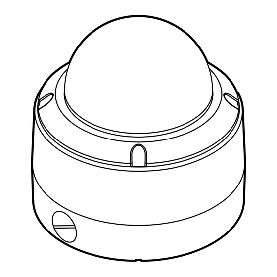
Introduction - Parts & Description Main Body Bottom of Main Body... -
Page 9: Installation
Installation - Camera ID Setup Before installing the camera, set up the DIP switch to con gure the Camera ID. DIP Switch for Camera ID Bottom of Main Body The ID number of the camera is set using binary numbers. See the example below. - Page 10 Installation - Terminal Blocks Connections Alarm Output - It connects to the alarm lights, siren or lamps, and it is activated according to the OSD menu setting. - There are 1 Alarm Output and it is relay contact type. Therefore, you do not have to care about polarity, AC/DC, and isolations between channels.
-
Page 11: Installation Using Surface Mount Bracket
Installation - Installation Using Surface Mount Bracket Disassemble the main body with the surface mount Template Sheet before installation the camera. Drilling the Hole Drilling a Hole on the Ceiling on the Ceiling Using provided template sheet, drill a hole (30mm diameter) on the ceiling panel to pass cables. - Page 12 Installation - Installation Using Ceiling Mount Bracket (Option) Disassemble the main body with the surface mount Drilling a Hole on the before installation the camera. Ceiling and Fixing the Anchor Bolts 1. Installing on the Concrete Ceiling Drilling a Hole on the Ceiling and Fixing the Anchor Bolts To install the ceiling mount bracket, drill four holes (6mm diameter/50mm depth) on the ceiling and insert...
- Page 13 Installation - Installation Using Wall Mount Bracket (Option) Disassemble the main body with the surface mount Drilling a Hole on the before installation the camera. Wall and Fixing the Anchor Bolts 1. Installing on the Concrete Wall Rubber Gasket Drilling a Hole on the Wall and Fixing the Anchor Bolts To install the wall mount bracket, drill four holes (6mm diameter/50mm depth) on the wall and insert...
- Page 14 Installation - Installation Using Sunshield Mount Disassemble the main body with the surface mount and open the junction box cover before installation the camera. Drilling a Hole on the Wall and Fixing the Anchor Fix the wall/ceiling Bolts mount bracket Drill a hole (6mm diameter/ 50mm depth) on the wall, and fix the anchor bolts.
- Page 15 Installation - Installation Using Ceiling Mount Bracket and Sunshield Dome (optional) Disassemble the main body with the surface mount Drilling a Hole on the before installation the camera. Ceiling and Fixing the Anchor Bolts 1. Installing on the Concrete Ceiling Drilling a Hole on the Ceiling and Fixing the Anchor Bolts To install the ceiling mount bracket, drill four holes...
- Page 16 Installation - Installation Using Wall Mount Bracket and Sunshield Dome (optional) Disassemble the main body with the surface mount before installation the camera. 1. Installing on the Concrete Wall Drilling a Hole on the Wall and Fixing the Anchor Bolts To install the wall mount bracket, drill four holes Drilling a Hole on the Passing the Cables...
-
Page 17: First Time Booting Up
Installation - First-time Booting Up Check Points before Operation 1. Before power is applied, please check the cables carefully. 2. The camera ID of the controller must be identical to that of the camera to be controlled. The camera ID can be check in the system information of OSD menu. -
Page 18: Check Points Before Operation
Installation- Check Points before Operation 1. Before you can start controlling your PTZ12X camera, you need to make sure the Camera’s ID, Baud Rate and Protocol are setup in the DVR or Joystick Controller. 2. In the DVR, go to Menu --> Device --> PTZ 3. -
Page 19: Special Functions
OSD - Special Functions Preset Group - You can setup and save the camera position. - The group function allows running sequence of presets, pattern and/or scans. - See the section ‘ROOT MENU>FUNCTION SETUP>PRESET SETUP’ for more detailed information. - See the section ‘ROOT MENU>FUNCTION SETUP>GROUP SETUP’... -
Page 20: Osd Information
OSD - OSD Information PRESET LABEL PATTERN1 Preset Label Action Title Temperature Alarm Input Information Relay Out Information 25 C 23/MAR/2009 Date / Time I - 2 O 1 24 00 00 Compass Direction 359/180/x100/SE CAM 1 Image Flip Zoom Magnification Tilt Angle in Degree Camera ID Pan Angle in Degree... -
Page 21: General Rules Of Menu Operation
OSD - General Rules of Menu Operation This page explains how to operate the OSD menu using keyboard controller or USB mouse. If there are no keys or ROOT MENU - - - - - - - - - - - - - - - - - - - - - - - - - - - functions described below, refer the manual of the keyboard <SYSTEM INFORMATION>... -
Page 22: Osd - Root Menu & System Information
OSD - ROOT MENU & SYSTEM INFORMATION ROOT MENU ROOT MENU To enter this screen, enter ‘Preset key + 95’. - - - - - - - - - - - - - - - - - - - - - - - - - - - <SYSTEM INFORMATION>... -
Page 23: Osd - Display Setup
OSD - DISPLAY SETUP (Privacy Zone) DISPLAY SETUP DISPLAY SETUP This menu defines enable/disable of OSD display on main screen. - - - - - - - - - - - - - - - - - - - - - - - - - - - If an item is set to be ‘AUTO’, the item is displayed only when the CAMERA ID PTZ INFORMATION... -
Page 24: Osd - Motion Setup & Parking Action
OSD - MOTION SETUP & PARKING ACTION SETUP MOTION SETUP MOTION SETUP Setup the general functions of pan/tilt motions. - - - - - - - - - - - - - - - - - - - - - - - - - - - PRESET LOCK PWR UP ACTION PRESET LOCK... -
Page 25: Osd - Motion Setup & Alarm Input
OSD - MOTION SETUP & ALARM INPUT SETUP This setup is not supported on some models. MOTION SETUP - - - - - - - - - - - - - - - - - - - - - - - - - - - PRESET LOCK ALARM INPUT SETUP PWR UP ACTION... -
Page 26: Osd - Function Setup > Preset Setup
OSD - FUNCTION SETUP > PRESET SETUP What is a Preset? A Preset is a unique command users can assign the camera. The PTZ39X supports up to 255 di erent Presets. Users can use 127 Presets to setup di erent positions for the camera Users can setup 1~128 Presets for di erent camera positions, except for preset 95. - Page 27 OSD - FUNCTION SETUP > PRESET SETUP LABEL PRESET SETUP Edits label to show on monitor when camera arrives at preset. - - - - - - - - - - - - - - - - - - - - - - - - - - - PRESET NO.
-
Page 28: Osd - Function Setup > Scan Setup
OSD - FUNCTION SETUP > SCAN SETUP SCAN SETUP FUNCTION SETUP By using the scan function, you can make the camera to move - - - - - - - - - - - - - - - - - - - - - - - - - - - between 2 preset positions repeatedly. -
Page 29: Osd - Function Setup > Pattern Setup
OSD - FUNCTION SETUP > PATTERN SETUP PATTERN SETUP Pattern function is that a camera memorizes the path (mostly FUNCTION SETUP - - - - - - - - - - - - - - - - - - - - - - - - - - - curve path) by joystick of controller for assigned time and <PRESET SETUP>... -
Page 30: Osd - Function Setup > Group Setup
OSD - FUNCTION SETUP > GROUP SETUP GROUP SETUP SCREEN The group function allows running sequence of presets, pattern FUNCTION SETUP - - - - - - - - - - - - - - - - - - - - - - - - - - - and/or scans. - Page 31 OSD - FUNCTION SETUP > GROUP SETUP EDIT GROUP - Selects Function Sequence After finishing setting up an ‘ACTION’, press near or enter key EDIT GROUP - - - - - - - - - - - - - - - - - - - - - - - - - - - to one-upper-level menu.
-
Page 32: Osd - Function Setup > Schedule Setup
OSD - FUNCTION SETUP > SCHEDULE SETUP SCHEDULE SETUP SCREEN The schedule function allows running an appropriate function FUNCTION SETUP - - - - - - - - - - - - - - - - - - - - - - - - - - - like preset, scan, pattern, group, home move at designated <PRESET SETUP>... - Page 33 OSD - FUNCTION SETUP > SCHEDULE SETUP SCHEDULE SETUP The second rule means camera will move to preset 12 position at - - - - - - - - - - - - - - - - - - - - - - - - - - - 7:00 on every wednesday.
-
Page 34: Osd - Camera Setup > White Balance Setup
OSD - CAMERA SETUP > WHITE BALANCE SETUP ZOOM CAMERA SETUP Setup the general functions of zoom camera module. ZOOM CAMERA SETUP - - - - - - - - - - - - - - - - - - - - - - - - - - - FOCUS MODE SEMIAUTO DIGITAL ZOOM... -
Page 35: Osd - Camera Setup > Auto Exposure Setup
OSD - CAMERA SETUP > AUTO EXPOSURE SETUP AE SETUP ZOOM CAMERA SETUP - - - - - - - - - - - - - - - - - - - - - - - - - - - WDR/BLC FOCUS MODE SEMIAUTO... -
Page 36: Osd - Camera Setup > Special
OSD - CAMERA SETUP > SPECIAL (HLC/ DNR) This setup is not supported on some models. ZOOM CAMERA SETUP - - - - - - - - - - - - - - - - - - - - - - - - - - - SPECIAL FOCUS MODE SEMIAUTO... -
Page 37: Osd - System Setup
OSD - SYSTEM SETUP SYSTEM SETUP SYSTEM SETUP <DATE/TIME SETUP> - - - - - - - - - - - - - - - - - - - - - - - - - - - <DATE/TIME SETUP> Start ‘DATE/TIME SETUP’ setup. <RELAY TYPE>... -
Page 38: System Setup
OSD - SYSTEM SETUP SET HOME POSITION Home position means the origin of pan angle calculation. SET HOME POSITION - - - - - - - - - - - - - - - - - - - - - - - - - - - The value of pan angle displayed on the screen is based on this home position. - Page 39 OSD - SYSTEM SETUP (BAUDRATE & PROTOCOL) PROTOCOL/BAUDRATE After installing the camera, you should set the communication SYSTEM SETUP - - - - - - - - - - - - - - - - - - - - - - - - - - - protocol and baudrate.
-
Page 40: Osd - System Initialize
OSD - SYSTEM INITIALIZE Initial Configuration Table SYSTEM INITIALIZE Camera ID - - - - - - - - - - - - - - - - - - - - - - - - - - - CLEAR ALL DATA PTZ Information AUTO CLR DISPLAY SET... -
Page 41: Dimension
Specification - Dimension Unit: mm 60.8 162.3 66.5 ¾ ” NPT ¾ ” NPT 83.5... -
Page 42: Dimensions Of Option Brackets
Specification - Dimensions of Option Brackets Wall Mount Bracket Ceiling Mount Bracket Unit: mm Unit: mm 112.6 4- 7 276.2 112.6 188.7 141.5 4-M4 355.5 83.5 112.6 141.5 4- 7 112.6 83.5... - Page 43 Specification - Dimensions of Option Sunshield Sun Shield Mount Bracket Unit: mm - 4 7...
- Page 44 Specification - Speci cation_x12 VIDEO Image Sensor 1/4" Sony Super HAD (Double Scan) CCD II Horizontal Resolution 750 TV Lines [B&W], 700 TV Lines [Color] Minimum Illumination Color: 0.5 Lux, 0.001 Lux [DSS ON] B&W: 0.2 Lux, 0.0004 Lux [DSS OFF] CVBS: 1.0Vp-p / 75 Ω...
-
Page 45: Troubleshooting
Troubleshooting Before sending your camera for repair, check the following or contact our technical support specialists. PROBLEM SOLUTION Notimage appears on the screen. Check that the power cable is connected properly to the camera and that it meets the camera’s power requirements. Check that the line connection between the camera and monitor is fixed properly.Check that you have properly connected BNC cable to the camera. -
Page 46: Warranty Information
WARRANTY INFORMATION Digital Watchdog (referred to as “the Warrantor”) warrants the Digital Watchdog Camera against defects in materials or workmanship as follows: LABOR : For the initial two (2) years and one (1) year on PTZ Zoom Module from the original purchase date, if the camera is determined to be defective, the Warrantor will repair or replace the unit with a new or refurbished product at its option at no charge. - Page 47 Appendix I Setting the Camera’s ID using the DIP Switch Use the following table as a quick reference to the Pin values and positions required for each individual ID number. The unique Pin combination equals a different ID you can use to define you camera in a situatoin where you want to control multiple cameras.
- Page 48 Appendix I Setting the Camera’s ID using the DIP Switch Pin Value...
- Page 49 Appendix I Setting the Camera’s ID using the DIP Switch Pin Value...
- Page 50 Appendix I Setting the Camera’s ID using the DIP Switch Pin Value...
- Page 51 Appendix I Setting the Camera’s ID using the DIP Switch Pin Value...
- Page 52 Appendix I Setting the Camera’s ID using the DIP Switch Pin Value...
-
Page 53: Appendix Ii
Appendix II Reserved Presets Reserved Preset Some preset numbers are reserved to special functions. Preset key + 95: Enters into OSD menu Preset key + 131~134: Runs pattern function 1 ~ 4 Preset key + 141~148: Runs scan function 1 ~ 8 Preset key + 151~158: Runs group function 1 ~ 8 Preset key + 161~164: Sets relay 1~ 4 output to OFF Set key + 161~164: Sets relay 1~ 4 output to ON... - Page 54 Appendix III How to Move Around the OSD Menu Using a USB Mouse Start OSD Menu Using the OSD menu, preset, pattern, scan, group, and alarm input function can be configured for each application. 1. Select Full Screen view on the selected PTZ camera 2.
- Page 55 Appendix III How to Move Around the OSD Menu Using a USB Mouse 5. Using the mouse, click on the are of the screen labeled: UP: to scroll up the menu DOWN: to scroll down the menu Left: Vertically move from one edit tab to the one to its left RIGHT: Vertically move from one edit tab to the one to its right.
- Page 56 Appendix III How to Move Around the OSD Menu Using a USB Mouse To move to a sub-menu 1. Click on the top/bottom of the screen to select the desired sub-menu from the list. 2. Once you have selected the sub-menu you want to enter, scroll the mouse’s wheel forward To exit a sub-menu 3.
- Page 57 Appendix III How to Move Around the OSD Menu Using a USB Mouse To move between input tabs 1. Using previous instructions, select the sub-menu and category you wish to modify 2. Scroll the mouse’s wheel forward to enter edit mode 3.
- Page 58 Appendix III How to Move Around the OSD Menu Using a USB Mouse 4. Click on the top/bottom of the screen to increase/reduce the values of the data you are modifying 5. When you have completed modifying the first data tab, click on the left side of the screen to move to the next data tab. 6.
- Page 59 Appendix IV How to Move Around the OSD Menu Using DW-KB100 Joystick Keyboard Note: Please consult your Joystick Controller’s manual for additional information and instructions.
- Page 60 5436 W Crenshaw St. Tampa, FL 33634 Tel : 866-446-3595 / 813-888-9555 Fax : 813-888-9262 www.Digital-Watchdog.com technicalsupport@dwcc.tv Technical Support Hours : Monday-Friday 8:30am to 8:00pm Eastern Time Correct Disposal of This Product (Waste Electrical & Electronic Equipment) (Applicable in the European Union and other European countries with separate collection systems) This marking on the product, accessories or literature indicates that the product and its electronic accessories (e.g.
Need help?
Do you have a question about the x12 WDR PTZ and is the answer not in the manual?
Questions and answers