Table of Contents
Advertisement
Quick Links
HD IP PTZ CAMERA
OUTDOOR HD IP PTZ CAMERA
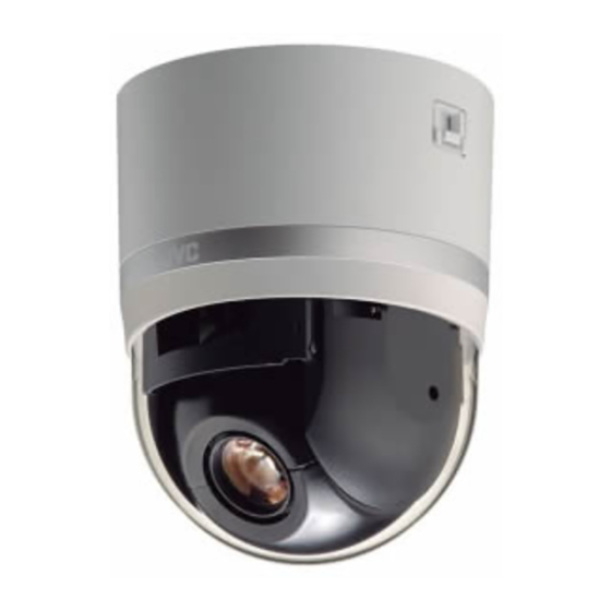
VN-H657BU
VN-H657WPBU
VN-H657BU
Mobile User Guide
When you are outside, you can refer to the instructions from your Android phone or iPhone.
http://manual3.jvckenwood.com/pro/mobile/global/
You can view the Mobile User Guide using the browser on your Android phone or iPhone.
For Customer Use:
Enter below the Serial No. which is located
on the body.
Retain this information for future reference.
Model No.
Serial No.
VN-H657WPBU
Please read the following before getting started:
Thank you for purchasing this product.
Before operating this unit, please read the
instructions carefully to ensure the best
possible performance.
INSTRUCTIONS
Specifications and appearance of this
unit are subject to change for further
improvement without prior notice.
Please check the latest version of the
INSTRUCTIONS from the following
Mobile User Guide or download the
PDF from the URL below.
LST1532-001A
Advertisement
Table of Contents

Related Manuals for JVC VN-H657WPBU


Summary of Contents for JVC VN-H657WPBU
-
Page 1: Mobile User Guide
HD IP PTZ CAMERA OUTDOOR HD IP PTZ CAMERA VN-H657BU INSTRUCTIONS VN-H657WPBU Specifications and appearance of this unit are subject to change for further improvement without prior notice. Please check the latest version of the INSTRUCTIONS from the following Mobile User Guide or download the... -
Page 2: Safety Precautions
Safety Precautions Slots and openings in the cabinet and the back or bottom are provided for ventilation, and to insure reliable IMPORTANT SAFEGUARDS operation of the appliance and to protect it from overheating, these Read all of these instructions. openings must not be blocked or Save these instructions for later use. - Page 3 Do not attempt to service this FOR USA AND CANADA appliance yourself as opening or removing covers may expose you to CAUTION dangerous voltage or other hazards. Refer all servicing to qualified service RISK OF ELECTRIC SHOCK personnel. DO NOT OPEN Unplug this appliance from the wall outlet and refer servicing to qualified CAUTION:...
- Page 4 This device complies with part 15 of the TO REDUCE THE RISK OF FIRE OR FCC Rules. Changes or modifications ELECTRIC SHOCK, DO NOT not approved by JVC KENWOOD could EXPOSE THIS APPLIANCE TO RAIN void the user's authority to operate the OR MOISTURE.
- Page 5 European representative of recovery and recycling in European JVC KENWOOD Corporation is: accordance with your national Union. JVC Technical Services Europe GmbH legislation. By disposing of this Konrad-Adenauer-Allee 1-11 product correctly, you will help 61118 Bad Vilbel to conserve natural resources...
- Page 6 Perform regular Mass : Approx. 2.0 kg (VN-H657BU) inspections for loosened screws and Approx. 5.6 kg (VN-H657WPBU) check whether there is any danger of If the strength is weak, the vibration will the unit falling off.
-
Page 7: Table Of Contents
[Image Settings] Settings ......92 Installation and Connection Preparations [PTZ Settings] ..........94 (VN-H657WPBU) ..........31 [PTZ Control] ..........97 Mounting the Camera (VN-H657WPBU) ..35 [Viewer Setup] ..........99 IP Address Settings [Unicast] Settings ......... 99 IP Address Setting Procedure ......38 [Multicast] Settings ........ -
Page 8: Features
Make use of an AC 24 V power supply when area. Pre-/post-recorded JPEG image files can be using the heater of VN-H657WPBU. sent to the FTP server by the alarm. Use a hub or a power supply device that supports PoE Plus (compliant with IEEE802.3at Type 2). -
Page 9: Precautions
Symbols used in this manual product will not work properly if it is tilted. Note : States precautions to be taken during VN-H657WPBU is specially designed to be operation. mounted on walls. Be sure to place the camera Memo : States restrictions on the functions or use head horizontally. -
Page 10: Carrying The Camera
AC 24 V power supply : -40 °C to 55 °C tape PoE Plus power supply : -10 °C to 55 °C * When power is supplied to VN-H657WPBU using PoE Plus, the heater will not work. Use an AC 24 V power supply when using the camera in an environment under -10 °C. - Page 11 Inserting the card energy conservation reasons. forcibly in the wrong orientation may damage the camera or the microSD card. (A p.29 [Insert a microSD card. (VN-H657BU)] ) (A p.33 [Insert a microSD card. (VN-H657WPBU)] ) Precautions...
-
Page 12: Zoom Operation
Auto Focus Others Auto Focus operation can be performed on this This camera will perform the initial operation of product after the pan/tilt/zoom (PTZ) operation pan/tilt/zoom upon powering on. It takes about stops. 90 seconds before the initial operation starts. For more details, refer to “Easy AF”... - Page 13 When using multicast, make use of an The time of the internal clock may be IGMPv2-compliant network switch. significantly out of alignment if the power of the Some switching hubs of products that are product is turned off for a long time or when there equipped with intelligent features may include a is prolonged power failure.
-
Page 14: Accessories
INSTRUCTIONS (Installation/IP Address Settings): 1 Warranty Card (for USA): 1 Template: 1 CD-ROM: 1 Wire Clamp: 1 Audio cable: 1 VN-H657WPBU INSTRUCTIONS (Installation/IP Address Settings): 1 Warranty Card (for USA): 1 CD-ROM: 1 Silica Gel: 3 A Camera fixing lock knob (x2) This mounts the camera on the ceiling and secures it so that it does not fall. - Page 15 I Dome cover L Audio terminal The dome cover is a delicate object. Handle it For connecting the supplied audio cable. with care. List of Audio Cable Signals Note : Cable color Signal Name Do not peel off the protective sheet which is Brown White Mic Input...
-
Page 16: Vn-H657Wpbu
VN-H657WPBU A Camera securing hole (x4) This hole is used for mounting the camera on the wall. B Cable connecting hole, cap Remove the cap and pull out the cables from this hole for connection. (A p.34 [Remove the cable connection cap.] ) C Fall prevention wire Connects the camera to the wall. - Page 17 It is usually set to ON. (A p.32 [Installation and Connection Preparations (VN-H657WPBU)] ) I microSD card slot Insert a microSD card. (A p.33 [Insert a microSD card. (VN-H657WPBU)] )
-
Page 18: About Microsd Cards
(VN-H657BU)] ) specifications. (A p.33 [Insert a microSD card. The microSDHC cards Class10 or higher (16 (VN-H657WPBU)] ) GB to 32 GB) with a guaranteed operating temperature of 85 °C or higher Estimated Recordable Time for Operation checks have been performed on the... -
Page 19: Alarm Input/Output Signal
Alarm Input/Output Signal Alarm Output Signal Connect to alarm devices such as alarm, indicator, light or buzzer. Alarm Input Signal Alarm output signal is an open collector output insulated with photo coupler. Connect to sensors such as infrared sensors, door sensors, metal sensors and manual switches. -
Page 20: Operating Environment
Operating Environment Network Ensure that there is sufficient network Recommended Computer bandwidth for the data volume to be sent out by Specifications the camera. Do not send multicast stream that : Windows 8 Pro, Windows 7 exceeds the bandwidth. If the entire bandwidth Professional (SP1), Windows XP is used by the multicast stream, control of this Professional, or Home Edition... - Page 21 Network Jitter User Name : admin When there is considerable network jitter, delay Password : jvc time may be prolonged and the image frame rate This camera fulfills the ONVIF Profile S. may drop. In the case of H.264, noise interference may occur and playback may fail.
-
Page 22: Images
Images Uploading and Downloading of the Language File You can change the language on settings page and H.264 Profiles “Built-in Viewer” of the camera. The camera supports both the H.264 Baseline Profile and H.264 High Profile standards. Procedure High Profiles can maintain high image quality with 1 Open the Settings page. -
Page 23: Pages Available To Each User
There are three access authorization levels to the [Network] camera. The factory settings are as follows. [Protocol] admin All operations and setting changes are allowed. [Multicast] (Default Password: “jvc”) [Access Restrictions] operator [Time] The following items cannot be operated, and setting changes are not permitted. [Basic [Password]... -
Page 24: Installation And Connection Preparations
Installation and Connection 2 Remove the ceiling mount section Preparations (VN-H657BU) from the camera unit. The ceiling mount section is attached to the camera unit during packaging of the product. Be sure to put on protective glasses to protect your Before installing the camera, remove the eyes from falling objects when mounting the ceiling mount section from the camera unit. -
Page 25: Connect The Power Cable
LAN environment, access attempts may fail due to IP address duplication. Set up an IP address by either using the JVC-VN-IP SettingTool (included on the supplied CD-ROM) or turning the power supply of each camera on separately to avoid duplication. - Page 26 7 Connect the alarm signal cable to the Caution alarm signal terminal. Connect the alarm signal terminal to external To supply power to this product, make use of AC devices, such as a sensor or buzzer. 24 V 50 Hz/60 Hz or PoE Plus (IEEE802.3at For information on the pin number and signal Type2).
- Page 27 8 Connect the audio cable 10 Mount the terminal cover. Get ready a separate cable for connecting to Return the terminal cover that was removed the audio device. in step 3 to its original position. The direction After connecting the audio cable (supplied) to pull out the cables changes according to to the audio terminal of the camera, connect the mounting method of the camera.
-
Page 28: Mounting The Camera (Vn-H657Bu)
Mounting the Camera Memo : (VN-H657BU) Always use three screws and mount securely. Tighten the screws again during maintenance just to be safe. The plastic parts on the ceiling fixing holes of the 1 With the FRONT mark (D) facing the ceiling mount section act as an insulation shooting direction, secure the ceiling between the ceiling mount section and the... - Page 29 3 Insert a microSD card. (VN-H657BU) C Turn the lever by 90 ° in the clockwise direction Get ready a formatted microSD card in to attach the microSD cover. advance. To attach the microSD cover, attach the tab, Refer to the following page for the types of followed by pushing it in the direction of the microSD cards compatible with this camera.
- Page 30 4 Mount the dome cover to the camera. Caution A Check that the dome cover and lens are free from dirt. The camera may fall if the fall prevention wire is not connected. Be sure to connect B Turn the dome cover in a clockwise direction to the fall prevention wire.
-
Page 31: Installation And Connection Preparations (Vn-H657Wpbu)
7 Lock the two camera fixing lock knobs, Connection Preparations and peel off the dome cover protection sheet. (VN-H657WPBU) When the camera is mounted on the ceiling mount section, lower the camera fixing lock knobs (x2) in the direction of the arrow and... -
Page 32: Remove The Dome Cover
When installing on a rainy day, ensure that raindrops do not enter the interior. Lens cap Memo : When installing the heater at an unrequired location, turn off the ON/OFF switch of the heater. Installation and Connection Preparations (VN-H657WPBU) - Page 33 Be microSD Card Slot careful not to lose it. When inserting or replacing a microSD card, be Lever careful not to drop the microSD cover or microSD card. microSD Card Insertion Mark Installation and Connection Preparations (VN-H657WPBU)
- Page 34 1 N·m (5 kgf·cm to 10 kgf·cm). If the screws are insufficiently tightened, the dome cover may fog due to moisture penetration. 6 Remove the cable connection cap. Remove the cap on the arm of the camera. Cable connection cap Installation and Connection Preparations (VN-H657WPBU)
-
Page 35: Mounting The Camera (Vn-H657Wpbu)
Set up an IP address by either using For your safety, hold the arm section during the JVC-VN-IP SettingTool (included on the installation. supplied CD-ROM) or turning the power supply After installing, paint the nuts and washers to of each camera on separately to avoid prevent corrosion. - Page 36 Note : Connect to an AC 24 V power supply when using the VN-H657WPBU in an environment below -10 °C. When power is supplied using PoE Plus, the heater will not work. Cross cables cannot be used with some computers.
- Page 37 For information on the color and signal name Waterproof of the audio cable, refer to the following. treatment (A p.16 [VN-H657WPBU] ) Connect the audio cable, followed by Note : winding the waterproof tape (adhesive). Ensure that waterproof treatment is performed.
-
Page 38: Ip Address Settings
Configure the Internet Explorer settings in order duplication. Set up an IP address by either using to establish connection between the computer the JVC-VN-IP SettingTool (included on the and the camera. supplied CD-ROM) or turning the power supply of each camera on separately to avoid duplication. -
Page 39: Step2 Internet Explorer Setting
Step2 Internet Explorer Setting Select [Enable]. 1 Launch the Internet Explorer on the computer. 2 When proxy settings are enabled in the Internet Explorer, follow the steps below to disable the proxy of the Internet Explorer. A Select in the sequence of [Tools]-[Internet 4 If ActiveX controls and plug-ins of Options]-[Connections]-[LAN Settings]. -
Page 40: Step3 Connecting The Camera To The Computer
[YES] button to proceed. 2 Enter the user name and password (login as “admin”). A Enter the user name. (default password is “admin”) B Enter a password. (default password is “jvc”) C Click OK. Step2 Internet Explorer Setting... -
Page 41: Step4 Ip Address Setting For The Camera
Access the [TOOL_E] folder of the supplied When selecting “DHCP Disable”: CD-ROM disk, and search for the camera in Select “DHCP Disable” for the [Network] option. the LAN using the “JVC-VN-SearchTool” of Then, enter required values in [IP Address], this folder. [Subnet Mask], and [Default Gateway]. - Page 42 B Select [Time Zone]. C Click to confirm. Memo : For information on the network settings, please consult your network administrator. If you enter the following URL directly into the address bar of Internet Explorer, you can open the [Basic Setting1] page after logging in as “admin”...
-
Page 43: How To Open The Settings Page
URL of the camera, refer to the following. (A p.38 [IP Address Setting Procedure] ) 2 Enter the user name and password. The factory default is “admin” and “jvc”. After entering a correct user name and password, the Built-in Viewer of the camera is displayed. -
Page 44: Built-In Viewer Menu List
Built-in Viewer Menu List - [Protocol] (*1) .......... p.75 - [Protocol Settings] ....... p.76 The following items can be set. Depending on the - [Standard Surveillance Protocol] ..p.76 logged-in user name, some items may not be set due to the access authorization. In such case, - [JPEG Streaming] ........ -
Page 45: [Basic Setting1] Page
[Basic Setting1] Page Subnet Mask Sets the subnet mask of camera. [Factory default: R255.255.255.0] This page is for performing basic setting related to the network. Default Gateway This page can be used during access using Sets the default gateway of camera. “admin”. -
Page 46: [Basic Setting2] Page
[Basic Setting2] Page Scenefile You can select the setting that is suitable for the shooting scene. You can select the following eight This is a page for specifying the basic settings scenes. You can customize the camera page related to the camera and encoding. You can settings (except Camera ID) stored in “Scenefile”. - Page 47 Encode Select the frame size for each screen of JPEG and H.264 from the following six patterns. o Selectable distribution size H.264 High 1920´1080 30 fps (Frame size: 1920´1080, frame rate: 30 fps, communication speed: 8 Mbps, bit rate: CBR, I Frame Interval: 30 frames) H.264 High 1920´1080 5 fps (Frame size: 1920´1080, frame rate: 5 fps,...
-
Page 48: [Advanced Settings] Page
[Advanced Settings] Page Memo : You can enter up to 40 characters consisting of alphabets (both upper case and lower case), [Camera] Page numerals, parentheses, commas, periods, spaces and hyphens. This is a page for specifying the camera settings. All characters entered in the JPEG comment Settings here are linked to the Camera item in the segment will be saved, but some characters [Basic Setting2] page. - Page 49 Iris 3D DNR You can set the convergence level for the iris. The noise on the screen will be reduced. The level Auto +1: of noise reduction effect increases in the order of Converges to a level brighter than “Auto”. LowNMidNHigh.
- Page 50 9 AWC R-Gain Note : When Sense Up is set to a value other than Sets the gain of R (red) when in the AWC mode. A “OFF”, flickers occur under the light of larger value increases the redness and a smaller value decreases the redness.
- Page 51 Day/Night Back Light Compensation Sets video to Black & White mode. Also allows you Set this feature when there is a bright light source to select from among 3 levels for automatically in the same direction as the object. Enables activating Black &...
-
Page 52: [Encoding] Page
[Encoding] Page When “Single-Encode” is selected in [Encode] This is a page for specifying settings on JPEG/H. Enables only Encoder No.1 out of the three 264 encoding. channels of encoders. The settings here are linked to the [Encode] item in the [Basic Setting2] page. - Page 53 Memo : When “Multi-Encode” is selected in [Encode] When “VBR” is set, the [Bitrate] setting uses 30 fps as a reference value. Each of the three channels of the encoder can be When the frame rate is low, the actual bitrate set to H.264 High, H.264 Baseline or JPEG, and a distributed may drop.
- Page 54 9 Framesize 9 I Frame Interval (when “H.264 Baseline” or “H.264 High” is selected) Select the frame size of each JPEG or H.264 screen. Encoding starts from the I-frame. Shortening the [Encoder No.1 settings: R1920´1080, 1280´960, interval stabilizes the picture quality even when 1280´720, 720´480, 640´480, 640´360, there are rapid changes in the video image.
-
Page 55: [Audio] Page
[Audio] Page Audio This is a page for specifying the audio settings. This page can be used during access using Communicate “admin” or “operator”. For setting the audio transmission mode. Click [Advanced Settings] in the side menu, and Half Duplex: click [Audio]. -
Page 56: [Alarm] Page
[Alarm] Page Upload This page sets actions to be taken if an alarm occurs. You can set up to five actions (No. 1 to No. Audio File No.1 to No.5 For registering the audio file to be output from the This page can be used during access using camera’s audio cable or terminal when an alarm is “admin”... - Page 57 {model name}”. (For example, the subject is Alarm from only when input terminal (“Pin Input1 Make”, “Pin VN-H657WPB in the case of VN-H657WPBU.) Input1 Break”, “Pin Input2 Make”, or “Pin Input2 Enter the message to send in [Mail Text]. Enter Break”) is selected for the [1st Trigger] trigger.
- Page 58 JPEG Attachment: Specify whether or not to attach an image file to UDP IP Address: the mail. To attach JPEG images, check the Enter the IP address or FQDN of the destination Attach box and select the transmission channel. of UDP notification. Encoder: UDP Port Number: Specifies an Encoder No.
-
Page 59: [Alarm Environment] Page
[Alarm Environment] Page Trigger Position Number Set the preset position number to be used as the This page sets up the alarm environment. trigger when [1st Trigger] is set to “Position”. This page can be used during access using [Set values: 0 to 99] “admin”... -
Page 60: [Ftp Recording] Page
[FTP Recording] Page Port Number Input the port number. This page describes setting procedures related to [Set values: 0 to R25 to 65535] recording. This page can be used during access using Send Mail Address “admin” or “operator”. Click [Advanced Settings] in the side menu, and Specify the sender’s mail address. - Page 61 Constant FTP Recording Settings for performing constant recording. Record Status 9 Encoder For selecting a recording mode. Selecting “ON” For selecting the encoder for performing constant recording. displays options after [Record Status]. [Set values: ON, ROFF] Memo : You can select a JPEG encoder number. FTP Server 9 Interval For setting the IP address or FQDN of the FTP...
- Page 62 9 Trigger1, Interval, Trigger2 9 Pre-Trigger Trigger1: For setting the FTP pre-recording trigger time For selecting the first trigger for performing (recording time before alarm input) in seconds. alarm recording. [Set values: 0 to R5 to 60]sec [Set values: RPin Input1 Make, Pin Input2 Make, 9 Post-Trigger Pin Input1 Break, Pin Input2 Break, Position, For setting the FTP post-recording trigger time...
-
Page 63: [Microsd Card Recording] Page
[microSD Card Recording] Page Settings This page describes setting procedures related to microSD card recording. This page can be used during access using “admin” or “operator”. Click [Advanced Settings] in the side menu, and click [microSD Card Recording]. Press the [OK] button to enable the new settings. - Page 64 9 Status 9 Status Displays the mount status of the microSD card. This is indicated as “Recording” when recording is Mounted: in progress, and as “No Recording” when recording A microSD card is mounted to the camera. is stopped. When only [Alarm] is selected, the Recording to or playback of data on the card can status is indicated as “Recording”...
- Page 65 Alarm Settings 9 Trigger2 For selecting the second trigger for starting alarm For setting the corresponding alarm trigger when recording. “Alarm” is selected in [Recording Mode]. [Set values: RDisable, Pin Input1 Make, Pin Input1 9 Trigger1 Break, Pin Input2 Make, Pin Input2 Break] For selecting the first trigger for starting alarm Memo : recording.
-
Page 66: [Ptz] Page
[PTZ] Page Encode Setting Select the H.264 encoder No. for performing This page allows you to specify the Auto Return, microSD card recording. Move Preset Position and Auto Flip settings. Specify the encoding settings in the [Encoding] This page can be used during access using page. - Page 67 Return Time Basic operation of Pan Limit This item sets the time to return the operation with When [Pan Limit] is set to “ON”, panning is only Auto Return. available in the effective area. [Set values: R1, 2, 3, 5, 10, 20, 30, 60] minutes When the camera is moved to prohibited area by some operation that has priority over [Pan Test...
- Page 68 Mode1: Tilt Limit When the camera faces bottom, it rotates 180° This item sets the movable range of the tilt (vertical) horizontally and stops. In this case, the operation during manual operation. operating direction of the camera is the same as When this item is set to 10°, the movable range of that of the Pan/Tilt operation.
-
Page 69: [Auto Patrol] Page
[Auto Patrol] Page Settings This function sets the Auto Patrol operation which There are three screens in Auto Patrol. patrols multiple positions at specified time (The screen below appears when [Auto Patrol 0] is intervals. You can set the order in which to view the clicked.) determined positions. -
Page 70: [Privacy Mask] Page
[Privacy Mask] Page Privacy Mask For specifying whether to activate the Privacy Mask Privacy Mask is a feature that enables masking of feature. a portion of the video image. When this is set to “ON”, the privacy mask specified You can set 8 rectangular privacy masks for this unit. -
Page 71: [Motion Detection] Page
[Motion Detection] Page Memo : Upon opening the Mask Setting screen, Auto This page is for setting motion detection. Flip switches temporarily to “OFF”. After closing This page can be used during access using the Mask Setting screen, the original settings “admin”... -
Page 72: [Audio Detection] Page
[Audio Detection] Page Settings This page sets the audio detection parameters. This page can be used during access using “admin” or “operator”. Click [Advanced Settings] in the side menu, and click [Audio Detection]. Press the [OK] button to enable the new settings. -
Page 73: [Tampering Detection] Page
[Tampering Detection] Page Peak Meter (No.1, No.2) This page sets the tampering detection For selecting the target for detection using the peak parameters. meter displayed at the top of the setting screen. Such cases are usually thought to be caused by A sound level below the detection level is indicated blocked lenses or obstructing objects. -
Page 74: [Network] Page
[Network] Page Settings This page sets the network settings. This page can be used during access using “admin”. Click [Network] in the side menu. Press the [OK] button to enable the new settings. If you change the settings, the camera will restart. -
Page 75: [Protocol] Page
[Protocol] Page 9 IP Address Sets the IP address of camera. This page sets the protocol. [Factory default: 192.168.0.2] This page can be used during access using “admin”. Subnet Mask Memo : Sets the subnet mask of camera. Press the [OK] button to enable the new [Factory default: 255.255.255.0] settings. - Page 76 SNMP Protocol Settings For setting SNMP. Sets the protocols. [Set values: ON, ROFF] HTTP/HTTPS AMX Device Discovery Protocol For selecting the protocol to use. You can change the AMX device detection [Set values: RHTTP, HTTPS] protocol. Set to “ON” when you are using the camera on AMX’s system.
-
Page 77: [Multicast] Page
[Multicast] Page 9 Framesize Displays the [Framesize] settings specified for This page is for setting manual multicast each encoder. transmission. (A p.54 [ Framesize ] ) All items can be set when you log in as “admin”. If you log in as “operator”, you are only allowed to 9 Framerate start or stop transmission. -
Page 78: [Access Restrictions] Page
[Access Restrictions] Page EncoderNo.4 This page is for setting client restrictions. For setting manual distribution by EncoderNo.4. This page can be used during access using “admin”. Destination Address Click [Advanced Settings] in the side menu, and For specifying the destination address for audio click [Access Restrictions]. -
Page 79: [Time] Page
[Time] Page Client Address This page sets the current clock time. Restrictions may be imposed on clients accessing This page can be used during access using the camera using the IP address. “admin”. Press the [OK] button to enable the new Access Restriction settings. -
Page 80: [Password] Page
[Password] Page SNTP Server Sets an IP address of NTP server. This page sets a password. [Factory default: 0.0.0.0] This page can be used during access using “admin”. Interval Note : Sets a unit and values of measurement for the time Be sure to handle the password carefully in case interval at which to access the NTP server. -
Page 81: [Maintenance] Page
[Maintenance] Page admin, operator, user This page maintains the camera system. This page can be used during access using User Name “admin”. You must set passwords for the “admin”, “operator” Click [Advanced Settings] in the side menu, and and “user”. click [Maintenance]. - Page 82 Memo : Auto Cleaning Executing update does not reset the camera settings. Auto Cleaning Note : You can set whether to automatically clean the Do not shut down the system and computer power and signal transmission components. power supplies when the firmware is being Setting to “ON”...
-
Page 83: [Miscellaneous] Page
[Miscellaneous] Page [Operation] Page This page displays the software information of the The operation status of the camera is displayed. camera. This page can be used during access using This page can be used during access using “admin” or “operator”. “admin”, “operator”... -
Page 84: [Settings] Page
[Settings] Page [Patrol Settings] Page Displays the firmware version and the current This page displays the information and settings of settings of the camera. Auto Patrol. This page can be used during access using This page can be used during access using “admin”... -
Page 85: List Of Factory Defaults Of Each Page
Framesize 1920´1080 Item Factory Settings Framerate 30 fps Camera ID Model Bitrate CBR 4096 kbps (In case of I Frame 30 Frame VN-H657WPBU: Interval VN-H657WPB) Encoder No.2 Encoding JPEG Scenefile General Framesize 640´480 Iris Auto Framerate 30 fps Color Level... - Page 86 Alarm Page Alarm Environment Page Item Factory Settings Item Factory Settings Action Disable SMTP Server 0.0.0.0 1st Trigger Pin Input1 Make Port Number Max. Interval Send Mail Address 2nd Trigger Disable POP before SMTP Disable Action Position Number(*1) POP Server 0.0.0.0 Mail Settings (*2) Unset...
- Page 87 microSD Card Recording Page Audio Detection Page Item Factory Settings Item Factory Settings microSD Card No.1,2 No.1 Status No.1 Audio Detection Record Status Detection Sensitivity Status No Recording Detection Time 1000 ms Recording Mode - No.2 Audio Detection Alarm Settings Detection Sensitivity 1st Trigger Pin Input1 Make...
- Page 88 Item Factory Settings Encoder No.1 Framesize 1920´1080 Password Displayed as ***. Default passwords Framerate 30 fps are: Destination 225.0.1.1 admin: jvc Address operator: jvc Destination 49152 user: jvc Port Password Re-Input Encoder No.2 Framesize 640´480 Maintenance Page Framerate 30 fps Destination 225.0.2.1...
-
Page 89: Built-In Viewer Operation
Built-in Viewer Operation If the display or configuration of the open window appears strange, check the computer settings as follows: The camera comes with a Built-in Viewer. Enter the IP address of the camera in the address A Select [Start]-[Control Panel]-[Appearance bar of Internet Explorer to start up the Built-in and Personalization]. -
Page 90: Built-In Viewer Screen Configuration
The default folder name is “model name”. (For example, the folder name is “VN-H657WPB” in the case of VN-H657WPBU.) The file name is made up of “year, month, day, hour, minute, second, and millisecond”. Memo : You can rename the folder in the [Other] settings. - Page 91 Encoder Note : Even when [Communicate] on the [Audio] page Select the encoder No. for streaming. is set to “Full Duplex”, audio from the camera’s [Set values: RNo.1, No.2, No.3] microphone may be interrupted momentarily Memo : when the [Speech] button is pressed. This is not When [Protocol] is set to “RTP(Multicast)”, you a malfunction.
-
Page 92: [Control]
[Control] White Balance For selecting the white balance control feature. [Image Settings] Settings 9 Mode ATW-Wide: Adjusts the picture quality. Switches to the Auto-Tracking White Balance This page can be used during access using (automatic color temperature tracking) Wide “admin” or “operator”. mode. - Page 93 9 [OnePushAWC] button Memo : The backlight compensation area is not linked Executes AWC (automatic white balance control). to the electronic zoom. Memo : To execute [OnePushAWC], fill the screen Day/Night completely with a white object in a location with Sets video to Black &...
-
Page 94: [Ptz Settings]
[PTZ Settings] This item sets the pan/tilt/zoom (PTZ) functions. This page can be used during access using “admin” or “operator”. While another menu is open, click [Control], followed by clicking [PTZ Settings] in the operation menu to open the setting screen. Preset Position Sets the camera preset position. - Page 95 Mode Auto Pan Select the [Mode] of the auto pan operation. Right: Rotate the camera horizontally in the right direction from the [Start]. Left: Rotate the camera horizontally in the left direction from the [Start]. Return: Move between [Start] and [Return] in the clockwise direction from the [Start] toward the [Return].
- Page 96 State Auto Trace [Record Start]: For setting Auto Trace. This item stores and The camera will start recording of Pan/Tilt and reproduces manual operations of the camera. Zoom operations. (for approximately 30 Click [Auto Trace] in the operation menu to open seconds) the setting screen.
-
Page 97: [Ptz Control]
[PTZ Control] Pan / Tilt / Zoom Pan / Tilt operation: Operates the pan/tilt/zoom (PTZ) function. Operate Press the arrow buttons to move the display area the camera to adjust the direction, angle and focus. in the direction indicated by the arrow. Release This page can be used during access using the button to stop the movement. - Page 98 Auto Trace: Memo : The configured Auto Trace operation is Pressing the [+], [-] or [Focus] button releases performed. Returns to the starting position after the Easy AF mode and activates the Manual completing the series of operations, and mode. resumes after 30 seconds.
-
Page 99: [Viewer Setup]
[Viewer Setup] HTTP Port You can change the port number to be used when the client computer accesses to the camera via [Unicast] Settings HTTP. Set to the same value as [HTTP Server Port] of the You can set the HTTP port and the JPEG frame rate [Protocol] page. -
Page 100: [Multicast] Settings
[Multicast] Settings Memo : Set the multicast IP address and multicast port You can set the individual IP address and multicast to the same value specified for the destination port for video images and audio received via address and destination port respectively in the multicast. -
Page 101: [On Screen Display] Settings
[On Screen Display] Settings Position Title When “ON” is selected, the position title is Sets a display item on the viewer screen. For the Built-in Viewer, characters are displayed as displayed in the lower left of the screen. overlay on the video image. [Set values: ON, ROFF] This page can be used during access using Disp MD / Tampering / Audio Detection... -
Page 102: [Audio Monitor] Settings
[Audio Monitor] Settings Receive For specifying settings related to audio For specifying settings related to reception of audio transmission on the Built-in Viewer. distributed by the camera. This page can be used during access using “admin” or “operator”. When the Control Menu is open, click [Viewer Setup] to switch to the Viewer Setup Menu. -
Page 103: [Other] Settings
To change the name of the folder for storing captured files, enter the folder name. [Factory setting (during installation of viewer): Model ] (For example, the folder name is “VN-H657WPB” in the case of VN-H657WPBU.) [Viewer Setup] -[Audio Monitor] Settings... -
Page 104: [Microsd Card] Operation Screen
[microSD Card] Operation Screen Clicking the [SD Card] button on the Built-in Viewer screen displays the operation menu of the microSD card. On the microSD card operation screen, you can play back videos stored in the microSD card, or save them to a computer. Memo : Videos stored in the microSD card of one camera cannot be played back on multiple units... -
Page 105: Exiting Built-In Viewer
Exiting Built-in Viewer [IN] button: Inputs the time of the video that is currently playing automatically into the date/time entry Click the [´] button at the right top corner of the field. (upper) window to exit the viewer. [OUT] button: Inputs the time of the video that is currently playing automatically into the date/time entry field. -
Page 106: Troubleshooting
N When power is supplied using PoE Plus, the heater will not work. Connect the Is there any problem with the power cable for VN-H657WPBU to an AC 24 V power supply connecting this product to the power supply unit? when using it in an environment under -10°C. - Page 107 I cannot display the Settings page of the No sound is heard from the microphone to camera. which the audio cable of the camera is connected. N Check the current settings of Internet Explorer. When a proxy server is in use, N Check the connection with the microphone.
- Page 108 Multicast images do not play. The image displayed is not smooth. N Start manual multicast transmission from the The camera image may not appear smooth at [Multicast] page of the camera. times due to factors such as fluctuations in the CPU and memory load, or network jitter.
- Page 109 Characters of the file name registered in the Unable to record to the microSD card. FTP server are garbled. N Make use of a microSD card that is usable on N When double-byte characters are to be used this camera. for the file name, make use of an FTP server (A p.18 [Compatible microSD Cards] ) for which the character code is EUC-JP.
-
Page 110: Consumable Parts
Approx. 2 million operations Focus operation Approx. 4 million operations Slip ring Approx. 5 million operations Approx. 50,000 hours Heater relay Approx. 100,000 (VN-H657WPBU) operations Thin coaxial cable Approx. 3 million operations * Replace the fan every five years. Consumable Parts... -
Page 111: Appendix (Restrictions During Multi-Encoding)
Appendix (Restrictions during Multi-encoding) Possible Encoder No.1 and No.2 Setting Combinations During multi-encoding, there is a limit to the total number of pixels per unit time that can be encoded simultaneously by three encoders (total frame size and frame rate processed by each encoder). Encoder No.2 cannot be set to a frame size with a resolution higher than that of Encoder No.1. - Page 112 Encoder No.2 settings Framesize Framerate 30 - 1 30 - 1 30 - 1 30 - 1 30 - 1 1920 1080 (*1) (*1) (*1) (*1) (*1) 25 - 1 (*2) (*2) (*2) (*2) (*2) 1280 30 - 1 (*2) (*2) (*2) (*2)
- Page 113 Restrictions when Encoder No.1 is set to 1920´1080 30 fps When Encoder No.1 is set to a frame size of 1920´1080 and a frame rate of 30 fps, Encoder No.3 will be subject to restrictions on the settable values depending on the setting of Encoder No.2.
-
Page 114: Specifications
Specifications Network section Image : JPEG, H.264 High Profile, compression H.264 Baseline Profile VN-H657BU and VN-H657WPBU format (Common Specifications) Frame size : 1920´1080, 1280´960, 1280´720, 720´480 (D1), Overall 640´480, 640´360, 352´240, 320´240 Alarm input : No-voltage a contact input, NPN... - Page 115 Ceiling mounting hole [Unit: mm] VN-H657BU Overall FRONT mark Front of camera Mass : Approx. 2.0 kg Φ160 Φ140 Surrounding : -10 °C to 50 °C (operation) Screw Camera outer temperature 0 °C to 40 °C (recommended) mounting diameter Ambient : 20 %RH to 90 %RH hole humidity...
- Page 116 Wall mounting hole [Unit: mm] VN-H657WPBU Overall Mass : Approx. 5.6 kg Surrounding temperature When heater is : -40 °C to 55 °C (operation) in use (*) -30 °C to 40 °C (recommended) When heater is : -10 °C to 55 °C (operation) not in use 0 °C to 40 °C (recommended)
- Page 117 LST1532-001A © 2013 JVC KENWOOD Corporation...
Need help?
Do you have a question about the VN-H657WPBU and is the answer not in the manual?
Questions and answers