Table of Contents
Advertisement
Quick Links
HD IP PTZ CAMERA
OUTDOOR HD IP PTZ CAMERA
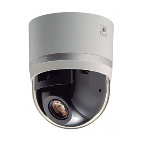
VN-H657U
VN-H657WPU
VN-H657U
Mobile User Guide
When you are outside, you can refer to the instructions from your Android or iPhone.
http://manual3.jvckenwood.com/pro/mobile/global/
You can view the Mobile User Guide using the browser on your Android phone or
iPhone.
For Customer Use:
Enter below the Serial No. which is located
on the body.
Retain this information for future reference.
Model No.
Serial No.
VN-H657WPU
Please read the following before getting started:
Thank you for purchasing this product.
Before operating this unit, please read the
instructions carefully to ensure the best
possible performance.
INSTRUCTIONS
Specifications and appearance of this
unit are subject to change for further
improvement without prior notice.
Please check the latest version of the
INSTRUCTIONS from the following
Mobile User Guide or download the
PDF from the URL below.
VN-H657U (A)
LST1528-001A
Advertisement
Table of Contents

Related Manuals for JVC VN-H657U


Summary of Contents for JVC VN-H657U
- Page 1 HD IP PTZ CAMERA OUTDOOR HD IP PTZ CAMERA VN-H657U INSTRUCTIONS VN-H657U (A) VN-H657WPU Specifications and appearance of this unit are subject to change for further improvement without prior notice. Please check the latest version of the INSTRUCTIONS from the following...
-
Page 2: Safety Precautions
Safety Precautions Slots and openings in the cabinet and the back or bottom are provided for ventilation, and to insure reliable IMPORTANT SAFEGUARDS operation of the appliance and to protect it from overheating, these Read all of these instructions. openings must not be blocked or Save these instructions for later use. - Page 3 Do not attempt to service this FOR USA AND CANADA appliance yourself as opening or removing covers may expose you to CAUTION dangerous voltage or other hazards. Refer all servicing to qualified service RISK OF ELECTRIC SHOCK personnel. DO NOT OPEN Unplug this appliance from the wall outlet and refer servicing to qualified CAUTION:...
- Page 4 This device complies with part 15 of the TO REDUCE THE RISK OF FIRE OR FCC Rules. Changes or modifications ELECTRIC SHOCK, DO NOT not approved by JVC KENWOOD could EXPOSE THIS APPLIANCE TO RAIN void the user's authority to operate the OR MOISTURE.
- Page 5 European representative of recovery and recycling in European JVC KENWOOD Corporation is: accordance with your national Union. JVC Technical Services Europe GmbH legislation. By disposing of this Postfach 10 05 04 product correctly, you will help 61145 Friedberg to conserve natural resources...
- Page 6 Perform regular Mass : Approx. 2.0 kg (VN-H657U) inspections for loosened screws and Approx. 5.6 kg (VN-H657WPU) check whether there is any danger of If the strength is weak, the vibration will the unit falling off.
-
Page 7: Table Of Contents
[PTZ Control] ..........81 [Viewer Setup] ..........84 Installation and Connection Preparations (VN-H657U) ............ 22 [Unicast] Settings ......... 84 Mounting the Camera (VN-H657U) ....25 [Multicast] Settings ........85 Installation and Connection Preparations [On Screen Display] Settings ....... 86 (VN-H657WPU) ..........27 [Other] Settings .......... -
Page 8: Features
The direct drive rotation platform rotates at a high speed of about 400 °/s both horizontally and * However, VN-H657U can only be used indoors. vertically, thus allowing the camera to move to the Do not use them in an outdoor environment or preset positions quickly. - Page 9 Internet Explorer as well as operation of the Built-in Viewer. The supplied CD-ROM contains “INSTRUCTIONS” (this manual), “API Guide” (pdf), “JVC-VN-SearchTool”, “JVC-VN-IP Settings Tool”, and “README” (txt). You can view the Mobile User Guide on an Android or iPhone terminal from a remote location.
-
Page 10: Precautions
Storage and Operating Environment therefore recommended that power be supplied to the camera at all times when the surrounding VN-H657U is an indoor camera. It cannot be used temperature is low. outdoors. VN-H657WPU is compliant with IP66, but this is VN-H657U is a pendant mount camera. -
Page 11: Auto Focus
For VN-H657WPU Wipe using a soft cloth. Wiping with thinner or benzene may melt or tarnish its surface. For tough stains, wipe using a cloth that is dipped into a neutral detergent diluted with Secure with water, followed by wiping with a dry cloth. tape When the same position is monitored continuously over a long period, the increased contact... - Page 12 The electronic shutter of this product is set to Zoom Operation “1/30” by default. For regions with a commercial The following phenomena are the results of the power supply frequency of 50 Hz, switch to built-in lens performance and are not “Flickerless”...
-
Page 13: Accessories
They Settings): 1 cannot be used as a substitute for a security Warranty Card (for USA): 1 alarm. JVC shall not be liable for any CD-ROM: 1 inconveniences or damages caused in the RJ-45 Conversion Connector: 1... -
Page 14: Name Of Parts
Name of Parts A Camera fixing lock knob (x2) This mounts the camera on the ceiling and secures it so that it does not fall. VN-H657U B Cable cover To pull the cables from the side and mount the Camera camera, remove the cover. - Page 15 Ceiling mount section H Fixing holes (x3) This hole is for mounting the ceiling clamping Terminal bracket to the ceiling or the ceiling recessed bracket (WB-S685U: Sold separately). I [AC24VHINPUT] AC 24 V input terminal For connecting to AC 24 V power. (A P23 [Connect the power cable.] ) J [10BASE-T/100BASE-TX] LAN cable connection terminal...
-
Page 16: Vn-H657Wpu
VN-H657WPU E Alarm signal cable (8 pcs) This cable is for alarm input and alarm output. (A P30 [Connect the alarm signal cable.] ) List of Alarm Signal Cable Signals Cable color Signal Name Brown Input 1 Input 1 (COM) Orange Input 2 Yellow... -
Page 17: Alarm Input/Output Signal
Alarm Input/Output Signal Alarm Output Signal Connect to alarm devices such as alarm, indicator, light or buzzer. Alarm Input Signal Alarm output signal is an open collector output insulated with photo coupler. Connect to sensors such as infrared sensors, door sensors, metal sensors and manual switches. -
Page 18: Operating Environment
Operating Environment Network Ensure that there is sufficient network Recommended Computer bandwidth for the data volume to be sent out by Specifications the camera. Do not send multicast stream that : Windows 7 Professional (SP1), exceeds the bandwidth. If the entire bandwidth Windows XP Professional, or is used by the multicast stream, control of this Home Edition (SP3) -
Page 19: Operating Protocol
User Name : admin Network Jitter Password : jvc This camera fulfills the ONVIF Profile S. When there is considerable network jitter, delay time may be prolonged and the image frame rate may drop. In the case of H.264, noise interference may occur and playback may fail. -
Page 20: Images
Images Settings Page H.264 Profiles Selection of Languages on Settings Page The camera supports both the H.264 Baseline Profile and H.264 High Profile standards. There is a radio button for selecting the language High Profiles can maintain high image quality with at the right top corner of the setting pages, however a low bit rate, but as the decoder needs to support the language will be automatically set according to... -
Page 21: Pages Available To Each User
There are three access authorization levels to the [Protocol] camera. The factory settings are as follows. admin [Multicast] All operations and setting changes are allowed. [Time] (Default Password: “jvc”) [Password] operator The following items cannot be operated, and [Maintenance] setting changes are not permitted. [Basic [Miscellaneous]... -
Page 22: Installation And Connection Preparations
If it is more than 6 mm, the screw will touch the ceiling and the camera cannot be Camera fixing installed horizontally. lock knob (x2) Use M4 fixing screws. Ceiling mount Camera Table etc Installation and Connection Preparations (VN-H657U) -
Page 23: Connect The Power Cable
IP address LAN specifications in advance. duplication. Set up an IP address by either using the JVC-VN-IP SettingTool (included on the supplied CD-ROM) or turning the power supply of each camera on separately to avoid duplication. - Page 24 When pulling out the cables from the side, used is within 50 m. In this case, move the cable remove the cable cover of the camera. away from the noise source. Cable cover Installation and Connection Preparations (VN-H657U)
-
Page 25: (Vn-H657U)
If the ceiling structure is metal and insulation is not provided between the camera and the ceiling structure, image noise may occur. Be sure to provide insulation. Mounting the Camera (VN-H657U) - Page 26 The camera cannot be mounted if the lock knobs are locked. When pulling out the cables from the side, remove the cable cover of the camera. (A P24 [Pulling out the cables from the side] ) Mounting the Camera (VN-H657U)
-
Page 27: Installation And Connection Preparations (Vn-H657Wpu)
Installation and Connection 4 Pull the cables from the hole in the Preparations (VN-H657WPU) wall. Pull the power cable, LAN cable and alarm signal cable from the wall. Be sure to put on protective glasses to protect your eyes from falling objects when mounting the LAN cable camera. - Page 28 When installing the dome cover, make use of the three catches and the center mark of the cover as a guide. Install such that the central mark appears above the JVC mark of the camera. Installation and Connection Preparations (VN-H657WPU)
-
Page 29: Mounting The Camera (Vn-H657Wpu)
For your safety, hold the arm section during duplication. Set up an IP address by either using installation. the JVC-VN-IP SettingTool (included on the After installing, paint the nuts and washers to supplied CD-ROM) or turning the power supply prevent corrosion. - Page 30 6 Connect the alarm signal cable. Caution Connect the alarm signal cable to external devices, such as a sensor or buzzer. To supply power to this product, make use of AC For information on the color and signal name 24 V 50 Hz/60 Hz or PoE Plus (IEEE802.3at of the alarm signal cable, refer to the Type2).
- Page 31 7 Attach the cap, and seal the cable connection hole and areas around the camera’s mounting surface and the four anchor bolt fasteners with a waterproof sealant (GE silicon). Waterproof treatment (x4) Waterproof treatment Note : Ensure that waterproof treatment is performed. Otherwise, the camera may malfunction due to rain water seepage.
-
Page 32: Ip Address Settings
Configure the Internet Explorer settings in order duplication. Set up an IP address by either using to establish connection between the computer the JVC-VN-IP SettingTool (included on the and the camera. supplied CD-ROM) or turning the power supply of each camera on separately to avoid duplication. -
Page 33: Step2 Internet Explorer Setting
Step2 Internet Explorer Setting Select [Enable]. 1 Launch the Internet Explorer on the computer. 2 When proxy settings are enabled in the Internet Explorer, follow the steps below to disable the proxy of the Internet Explorer. A Select in the sequence of [Tools]-[Internet 4 If ActiveX controls and plug-ins of Options]-[Connections]-[LAN Settings]. -
Page 34: Step3 Connecting The Camera To The Computer
[YES] button to proceed. 2 Enter the user name and password (login as “admin”). A Enter the user name. (default password is “admin”) B Enter a password. (default password is “jvc”) C Click OK. Step2 Internet Explorer Setting... -
Page 35: Step4 Ip Address Setting For The Camera
Access the [TOOL_E] folder of the supplied When selecting “DHCP Disable”: CD-ROM disk, and search for the camera in Select “DHCP Disable” for the [Network] option. the LAN using the “JVC-VN-SearchTool” of Then, enter required values in [IP Address], this folder. [Subnet Mask], and [Default Gateway]. - Page 36 B Select [Time Zone]. C Click to confirm. Memo : For information on the network settings, please consult your network administrator. If you enter the following URL directly into the address bar of Internet Explorer, you can open the [Basic Setting1] page after logging in as “admin”...
-
Page 37: How To Open The Settings Page
- [Alarm] (*2) ..........P 48 2 Enter the user name and password. - [Alarm Environment] (*2) ......P 50 The factory default is “admin” and “jvc”. After entering a correct user name and - [Alarm Output] ........P 51 password, the Built-in Viewer of the camera is displayed. -
Page 38: [Basic Setting1] Page
[Basic Setting1] Page 9 Default Gateway Sets the default gateway of camera. Enter 0.0.0.0 if you do not want to set a default This page is for performing basic setting related to gateway. the network. [Factory default: R0.0.0.0] This page can be used during access using “admin”. -
Page 39: [Basic Setting2] Page
[Basic Setting2] Page 9 Scenefile You can select the setting that is suitable for the shooting scene. You can select the following eight This page sets fundamental camera and encoding scenes. You can customize the camera page parameters. This page can be used during access settings (except Camera ID) stored in “Scenefile”. - Page 40 Encode Select the frame size for each screen of JPEG and H.264 from the following six patterns. o Selectable distribution size H.264 High 1920´1080 30 fps (Frame size: 1920´1080, frame rate: 30 fps, communication speed: 8 Mbps, bit rate: CBR, I Frame Interval: 30 frames) H.264 High 1920´1080 5 fps (Frame size: 1920´1080, frame rate: 5 fps,...
-
Page 41: [Advanced Settings] Page
[Advanced Settings] Page Memo : You can enter up to 40 characters consisting of alphabets (both upper case and lower case), [Camera] Page numerals, parentheses, commas, periods, spaces and hyphens. This page sets the camera’s parameters. Settings All characters entered in the JPEG comment here are linked to the Camera items in the [Basic segment will be saved, but some characters Setting2] page. - Page 42 Iris 3D DNR You can set the convergence level for auto iris. The noise on the screen will be reduced. The level Auto +1: of noise reduction effect increases in the order of Converges to a level brighter than “Auto”. LowNMidNHigh [Set values: OFF, Low, RMid, High] Auto:...
- Page 43 9 AWC R-Gain Note : When Sense Up is set to a value other than Sets the gain of R (red) when in the AWC mode. A “OFF”, flickers occur under the light of larger value increases the redness and a smaller value decreases the redness.
- Page 44 Day/Night Back Light Compensation Sets video to Black & White mode. Also allows you Set this feature when there is a bright light source to select from among 3 levels for automatically in the same direction as the object. Enables activating Black &...
-
Page 45: [Encoding] Page
When “Single-Encode” is selected in [Encode] [Encoding] Page Enables only Encoder No.1 out of the three This page sets the JPEG/H.264 encoding channels of encoders. parameters. Settings here are linked to the [Encode] item of [Basic Setting2] page. (A P39 [[Basic Setting2] Page] ) This page can be used during access using “admin”... - Page 46 VBR: When “Multi-Encode” is selected in [Encode] The bit rate varies according to the condition of Each of the three channels of the encoder can be input video signals. The picture quality is stable set to H.264 High, H.264 Baseline or JPEG, and a but it is difficult to estimate the bit rate.
- Page 47 9 Framesize 9 I Frame Interval (when “H.264 Baseline” or “H.264 High” is selected) Select the frame size of each JPEG or H.264 screen. Encoding starts from the I-frame. Shortening the [Encoder No.1 settings: R1920´1080, 1280´960, interval stabilizes the picture quality even when 1280´720, 720´480, 640´480, 640´360, there are rapid changes in the video image.
-
Page 48: [Alarm] Page
[Alarm] Page Action Selects the action to perform when the alarm is This page sets actions to be taken if an alarm activated. occurs. You can set up to five actions (No. 1 to No. Disable: Performs no action. This page can be used during access using Mail: “admin”... - Page 49 1st Trigger Memo : You cannot select [JPEG Attachment] if there is Select the 1st trigger to perform an action. no channel with Encode set to JPEG. [Set values: RPin Input1 Make, Pin Input1 Break, Pin Input2 Make, Pin Input2 Break, Position, Motion Detection, Tampering Detection, Time, FAN Stop] TCP IP Address:...
-
Page 50: [Alarm Environment] Page
[Alarm Environment] Page Action Position Number Set the position number to move to when [Action] This page sets up the alarm environment. item is set to “Position”. This page can be used during access using “admin” or “operator”. [Set values: 0 to 99] Click [Advanced Settings] in the side menu, and Memo : click [Alarm Environment]. - Page 51 Mail Settings Alarm Output For setting the mail environment when [Mail] is Configure settings related to alarm output from an alarm output cable or connector. specified as an action on the Alarm page. If [SMTP Server], [Port Number], and [Send Mail Address] 9 Duration are set, the alarm action is displayed as “Preset”.
-
Page 52: [Ftp Recording] Page
[FTP Recording] Page Record Status For selecting a recording mode. Selecting “ON” This page describes setting procedures related to recording. displays options after [Record Status]. This page can be used during access using [Set values: ON, ROFF] “admin” or “operator”. FTP Server Click [Advanced Settings] in the side menu, and click [Record Status]. - Page 53 Constant 9 Trigger1, Interval, Trigger2 Trigger1: Settings for performing constant recording. Select the 1st trigger to perform an action. 9 Encoder [Set values: RPin Input1 Make, Pin Input2 Make, Pin Input1 Break, Pin Input2 Break, Position, For selecting the encoder for performing constant Motion Detection, Tampering Detection, Time, recording.
-
Page 54: [Ptz] Page
[PTZ] Page 9 Return Time This item sets the time to return the operation with This page allows you to specify the Auto Return, Auto Return. Move Preset Position and Auto Flip settings. [Set values: R1, 2, 3, 5, 10, 20, 30, 60] minutes This page can be used during access using “admin”... - Page 55 9 Tilt Limit Basic operation of Pan Limit This item sets the movable range of the tilt (vertical) When [Pan Limit] is set to “ON”, panning is only operation during manual operation. available in the effective area. When this item is set to 10°, the movable range of When the camera is moved to prohibited area by the tilt operation is from 10°...
-
Page 56: [Auto Patrol] Page
Mode1: [Auto Patrol] Page When the camera faces bottom, it rotates 180° This function sets the Auto Patrol operation which horizontally and stops. In this case, the patrols multiple positions at specified time operating direction of the camera is the same as intervals. -
Page 57: [Privacy Mask] Page
Settings [Privacy Mask] Page There are three screens in Auto Patrol. Privacy Mask is a feature that enables masking of (The screen below appears when [Auto Patrol 0] is a portion of the video image. clicked.) You can set 8 rectangular privacy masks for this unit. - Page 58 Privacy Mask Note : The tilt angle where mask can be set is within For specifying whether to activate the Privacy Mask 40 ° from the horizontal position. feature. The default home position (45 ° from the When this is set to “ON”, the privacy mask specified horizontal position) is outside the range of the in [Mask Setting] will appear on the screen.
-
Page 59: [Motion Detection] Page
Settings [Motion Detection] Page This page is for setting motion detection. This page can be used during access using “admin” or “operator”. The area valid for motion detection is displayed in blue. When motion is detected, the area around the screen is highlighted in red. -
Page 60: [Tampering Detection] Page
Settings [Tampering Detection] Page This page sets the tampering detection parameters. Such cases are usually thought to be caused by blocked lenses or obstructing objects. This page can be used during access using “admin” or “operator”. Click [Advanced Settings] in the side menu, and click [Tampering Detection]. -
Page 61: [Network] Page
[Network] Page 9 IP Address Sets the IP address of camera. This page sets the network settings. [Factory default: 192.168.0.2] This page can be used during access using “admin”. 9 Subnet Mask Click [Network] in the side menu. Sets the subnet mask of camera. Press the [OK] button to enable the new [Factory default: 255.255.255.0] settings. -
Page 62: [Protocol] Page
[Protocol] Page 9 Local Certification This page is for creating a new server certificate for This page sets the protocol. local authentication. This page can be used during access using Press the [Create Server Certificate] button to “admin”. create the server certificate. Memo : Note : Press the [OK] button to enable the new... - Page 63 9 Common Name 9 SNMP Enter the administrator name or server’s host name For setting SNMP. of the local certification authority. [Set values: ON, ROFF] 9 Mail Address 9 AMX Device Discovery Protocol Enter the administrator’s mail address. You can change the AMX device detection protocol.
-
Page 64: [Multicast] Page
[Multicast] Page 9 Framerate Displays the [Framerate] settings specified for This page is for setting manual multicast each encoder. transmission. (A P47 [ Framerate ] ) This page can be used during access using The frame rate can be changed when Encode is set “admin”... -
Page 65: [Time] Page
[Time] Page SNTP Server Sets an IP address of NTP server. This page sets the current clock time. [Factory default: 0.0.0.0] This page can be used during access using “admin”. Interval Press the [OK] button to enable the new settings. Sets a unit and values of measurement for the time If the [OK] button is pressed upon entering an interval at which to access the NTP server. -
Page 66: [Password] Page
[Password] Page admin, operator, user This page sets a password. 9 User Name This page can be used during access using You must set passwords for the “admin”, “operator” “admin”. and “user”. Note : Memo : Be sure to handle the password carefully in case You can set up to four users each for “admin”, you forget it. -
Page 67: [Maintenance] Page
[Maintenance] Page Note : Do not shut down the system and computer This page maintains the camera system. power supplies when the firmware is being This page can be used during access using updated and when the camera is restarting “admin”. -
Page 68: [Miscellaneous] Page
[Miscellaneous] Page [Operation] Page This page displays the software information of the The operation status of the camera is displayed. camera. This page can be used during access using This page can be used during access using “admin” or “operator”. “admin”, “operator”... -
Page 69: [Settings] Page
[Settings] Page [Position List] Page Displays the firmware version and the current Displays information on the preset position. settings of the camera. This page can be used during access using This page can be used during access using “admin” or “operator”. “admin”... -
Page 70: [Patrol Settings] Page
[Patrol Settings] Page This page displays the information and settings of Auto Patrol. This page can be used during access using “admin” or “operator”. The patrol information consists of three screens. (The screen below appears when [Patrol Settings0] is clicked.) [Advanced Settings] Page - [Patrol Settings] Page... -
Page 71: List Of Factory Defaults Of Each Page
List of Factory Defaults of Alarm Page Each Page Item Factory Settings Action Disable 1st Trigger Pin Input1 Make Camera Page Max. Interval Item Factory Settings 2nd Trigger Disable Camera ID Model Action Position Number(*1) (In case of Mail Settings (*2) Unset VN-H657WPU: Mail Address (*2) - Page 72 Alarm Environment Page PTZ Page Item Factory Settings Item Factory Settings SMTP Server 0.0.0.0 Auto Return Mode Port Number Return Time 1 minute Send Mail Address EZoom Limit POP before SMTP Disable Pan Limit POP Server 0.0.0.0 Tilt Limit 0 Degree Port Number Speed High...
- Page 73 Factory Settings Item Factory Settings HTTP/HTTPS HTTP Password Displayed as ***. Default passwords HTTP Server Port are: HTTPS Server Port admin: jvc SNMP operator: jvc AMX Device Discovery user: jvc Protocol Password Re-Input ONVIF Maintenance Page JPEG Streaming Client Number...
-
Page 74: Built-In Viewer Operation
Built-in Viewer Operation Built-in Viewer Screen Configuration The camera comes with a Built-in Viewer. Enter the IP address of the camera in the address bar of Internet Explorer to start up the Built-in Memo : Viewer. The Built-in Viewer enables operations Built-in Viewer settings are stored in cookies. - Page 75 Viewer Setup Note : If you select “RTP(Multicast)” and start the Switches the Operation Menu to the Viewer Setup Built-in Viewer, you may be alarmed by the Menu. Windows Firewall. Click this button when you want to configure the In this case, select “Do not block” and proceed settings of [Unicast], [Multicast], [On Screen to the next step.
-
Page 76: [Control]
[Control] White Balance For selecting the white balance control feature. [Image Settings] Settings 9 Mode ATW-Wide: Adjusts the picture quality. Switches to the Auto-Tracking White Balance This page can be used during access using (automatic color temperature tracking) Wide “admin” or “operator”. mode. - Page 77 9 [OnePushAWC] button Day/Night Executes AWC (automatic white balance control). Sets video to Black & White mode. Also allows you to select from among 3 levels for automatically Memo : activating Black & White mode in low-light To execute [OnePushAWC], fill the screen conditions.
-
Page 78: [Ptz Settings]
[PTZ Settings] This item sets the PTZ functions. This page can be used during access using “admin” or “operator”. While another menu is open, click [Control] to switch to the Control Menu. Click [PTZ Settings] to open the Settings screen. Preset Position Sets the camera preset position. - Page 79 Auto Pan Mode Select the [Mode] of the auto pan operation. Right: Rotate the camera horizontally in the right direction from the [Start]. Left: Rotate the camera horizontally in the left direction from the [Start]. Return: Move between [Start] and [Return] in the clockwise direction from the [Start] toward the [Return].
- Page 80 Auto Trace State For setting Auto Trace. This item stores and [Record Start]: reproduces manual operation. The camera will start recording of Pan/Tilt and Click [Auto Trace] on the left side of the screen Zoom operations. (for approximately 30 to open the setting screen. seconds) As Auto Trace performs simple saving of manual [Record Stop]:...
-
Page 81: [Ptz Control]
[PTZ Control] Pan / Tilt / Zoom Pan / Tilt operation: Controls the PTZ function. Operate the camera to Press the arrow buttons to move the display area adjust the direction, angle and focus. in the direction indicated by the arrow. Release This page can be used during access using the button to stop the movement. - Page 82 Auto Function Preset Position Select an Auto action, and press the [Start] or Select a preset position, and press the [GoTo] [Stop] button. button. When the selected position has been registered, the camera will move to the selected [Start] button: position.
- Page 83 Pan / Tilt / Zoom Pan / Tilt operation: Press the arrow buttons to move the display area in the direction indicated by the arrow. Release the button to stop the movement. Press the [H] button to move to the home position.
-
Page 84: [Viewer Setup]
[Viewer Setup] HTTP Port You can change the port number to be used when the client computer accesses to the camera via [Unicast] Settings HTTP. Set to the same value as [HTTP Server Port] of the You can set the HTTP port and the JPEG frame rate [Protocol] page. -
Page 85: [Multicast] Settings
[Multicast] Settings Multicast IP Address You can change the multicast IP address. You can set the IP address and multicast port for [Factory default: 225.0.1.1] video images via multicast. This page can be used during access using Multicast Port “admin” or “operator”. When the Control Menu is open, click [Viewer You can change the multicast port number. -
Page 86: [On Screen Display] Settings
[On Screen Display] Settings Position Title When “ON” is selected, the position title is Sets a display item on the viewer screen. For the Built-in Viewer, characters are displayed as displayed in the lower left of the screen. overlay on the video image. [Set values: ON, OFF] This page can be used during access using Disp MD / Tampering... -
Page 87: [Other] Settings
Exiting Built-in Viewer [Other] Settings When you are using the JPEG data compression, you can record still images. Click the [´] button at the right top corner of the You can rename the folder which stores a captured window to exit the viewer. file. -
Page 88: Troubleshooting
N If you have a computer connected to the same LAN, is used to supply power. search for the IP address using “JVC-VN-SearchTool” on the computer. Is connection established using a PoE Plus (compliant with IEEE802.3at Type 2) power supply device and a LAN cable of Category 5e or higher? I cannot display the Settings page of the camera. - Page 89 Unable to install Built-in Viewer/a warning Multicast images do not play. message appears when I start the Built-in Viewer. N Start manual multicast streaming from the N Check the current settings of Internet Explorer. The [Multicast] page of the camera. Built-in Viewer consists of a software component (A P64 [[Multicast] Page] ) called ActiveX.
- Page 90 A white zone appears in the Built-in Viewer. Characters of the file name registered in the FTP server are garbled. For some computers, if [Start]-[Control Panel]-[Adjust N When double-byte characters are to be used for the screen resolution]-[Make text and other items larger or file name, make use of an FTP server for which the smaller] is set to “Medium - 125%”...
-
Page 91: Consumable Parts
Consumable Parts The following are consumable parts. They must be replaced once they reach their lifetime. The lifetime is only an estimation and differs according to the usage environment and conditions. Replacement of consumable parts is chargeable within the guarantee period. Consumable Parts Estimated Lifetime Camera module... -
Page 92: Appendix (Restrictions During Multi-Encoding)
Appendix (Restrictions during Multi-encoding) Possible Encoder No.1 and No.2 Setting Combinations During multi-encoding, there is a limit to the total number of pixels per unit time that can be encoded simultaneously by three encoders (total frame size and frame rate processed by each encoder). Encoder No.2 cannot be set to a frame size with a resolution higher than that of Encoder No.1. - Page 93 Encoder No.2 settings Framesize Framerate 30 - 1 30 - 1 30 - 1 30 - 1 30 - 1 1920 1080 (*1) (*1) (*1) (*1) (*1) 25 - 1 (*2) (*2) (*2) (*2) 1280 30 - 1 (*2) (*2) (*2) (*2) 1280...
- Page 94 Restrictions when Encoder No.1 is set to 1920´1080 30 fps When Encoder No.1 is set to a frame size of 1920´1080 and a frame rate of 30 fps, Encoder No.3 will be subject to restrictions on the settable values depending on the setting of Encoder No.2.
-
Page 95: Specifications
Specifications LAN Specifications Compliant with IEEE802.3 and IEEE802.3u Communication : IPv4, HTTP, HTTPS, TCP, VN-H657U and VN-H657WPU (Common protocol RTSP/RTCP/RTP, FTP, SMTP, Specifications) DHCP, SNTP, SNMP, ICMP, UDP, IGMP, DNS, ARP Overall Lens Alarm input : No-voltage a contact input, NPN... - Page 96 Ceiling mounting hole [Unit: mm] VN-H657U Overall FRONT mark Front of camera Mass : Approx. 2.0 kg Φ160 Φ140 Surrounding : -10 °C to 50 °C (operation) Screw Camera outer temperature 0 °C to 40 °C (recommended) mounting diameter Ambient...
- Page 97 Wall mounting hole [Unit: mm] VN-H657WPU Overall Mass : Approx. 5.6 kg Surrounding temperature When heater is : -40 °C to 55 °C (operation) in use (*) -30 °C to 40 °C (recommended) When heater is : -10 °C to 55 °C (operation) not in use 0 °C to 40 °C (recommended) Ambient...
- Page 98 LST1528-001A © 2013 JVC KENWOOD Corporation...
Need help?
Do you have a question about the VN-H657U and is the answer not in the manual?
Questions and answers