
Related Manuals for N-Tron 7014TX


Summary of Contents for N-Tron 7014TX
-
Page 1: User Manual
7014 Series Industrial Gigabit Ethernet Switch User Manual & Installation Guide (Revised 2011-07-21) page 1 of 152... -
Page 2: Table Of Contents
7014TX, 7014FX2, and 7014FXE2 Industrial Gigabit Ethernet Switch Installation Guide ........7 Safety Warnings ................................8 Installation .................................. 10 Connecting the Unit ..............................14 Overview of Advanced Features ..........................18 Mode of Operation .................................. 18 Port Security .................................... 18 Port Mirroring ..................................18 Port Trunking .................................. - Page 3 Help – BPCL ................................... 86 Help – IGMP ................................... 87 Help – Bridging ..................................88 Help – RSTP ................................... 89 Help – Event Log ..................................90 Help – Firmware/Config ................................. 91 Help – Logical View ................................92 Help – User Mgmt ................................... 93 Help –...
- Page 4 Set Username ..................................110 Set Password ..................................110 Set IP Address of FTP server ..............................110 Set Name of the Remote File ..............................110 Display FTP related configuration parameters ........................111 Perform the configuration file transfer action ........................111 Perform the image file transfer action ........................... 111 Port Manager Commands ............................
- Page 5 Set VLAN to defaults ................................125 Set VLAN Ingress Filter ............................... 125 Get VLAN Ingress Filter ............................... 125 Get VLAN info ..................................126 Eventlog Related Commands ........................... 127 Get Eventlog count ................................127 Get Eventlog level ................................. 127 Get Eventlog size .................................. 127 Set Eventlog level .................................
- Page 6 Example 4 – Basic understanding of Hybrid VLANs ......................147 Example 5 – Basic understanding of Overlapping VLANs....................148 Example 6 – Basic understanding of VLANs with Multicast Filtering ................. 149 N-TRON Limited Warranty ............................. 152 (Revised 2011-07-21) page 6 of 152...
-
Page 7: 7014Tx, 7014Fx2, And 7014Fxe2 Industrial Gigabit Ethernet Switch Installation Guide
7014TX, 7014FX2, and 7014FXE2 Industrial Gigabit Ethernet Switch Installation Guide The N-TRON 7014 Series Gigabit compatible Industrial Ethernet Switch offers outstanding performance and ease of use. It is ideally suited for connecting Ethernet enabled industrial and or security equipment and is a fully managed switch. -
Page 8: Safety Warnings
The information contained in this document is subject to change without notice. N-Tron Corp. makes no warranty of any kind with regard to this material, including, but not limited to, the implied warranties of merchantability or fitness for a particular purpose. In no event shall N-Tron Corp. - Page 9 ENVIRONMENTAL SAFETY WARNING: Disconnect the power and allow to cool 5 minutes before touching. ELECTRICAL SAFETY WARNING: Disconnect the power cable before removing any modules, or any enclosure panel. WARNING: Do not operate the unit with the any cover removed. WARNING: Properly ground the unit before connecting anything else to the unit.
-
Page 10: Installation
PACKAGE CONTENTS Please make sure the 7014 Series Gigabit Ethernet Switch package contains the following items: 7014 Series Switch Product CD Contact your carrier if any items are damaged. Installation Read the following warning before beginning the installation: WARNING Never install or work on electrical equipment or cabling during periods of lightning activity. Never connect or disconnect power when hazardous gasses are present. -
Page 11: Din Rail Mounting
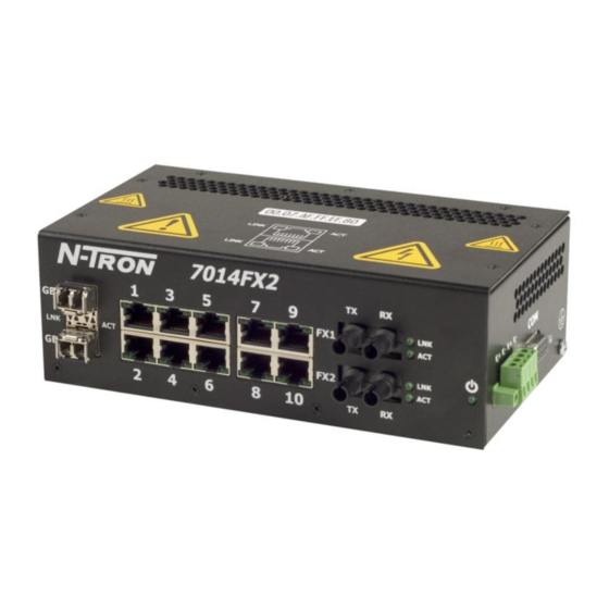
DIN RAIL MOUNTING Install the unit on a standard 35mm Din-Rail. Recess the 7014TX unit to allow at least 3” of horizontal clearance for fiber cable bend radius. Recess the 7014FX2 unit to allow at least 5” of horizontal clearance for fiber cable bend radius. - Page 12 FRONT PANEL From Top to Left: Gigabit Ports 1000 Base SFP Copper or Fiber Transceivers (Optional) RJ45 Ports Auto Sensing 10/100 Base-TX Connections Fiber Ports 100 Base-FX Connections (only on 7014FX2 model) Green LED lights when Power is supplied to the unit NOTE: The RJ45 data port has two LED‟s located on each connector.
- Page 13 DC Voltage sources. This device will draw current from both sources simultaneously. Use 16-28 gauge wire when connecting to the power supply. Recommended 24V DC Power Supplies, similar to: N-Tron‟s P/N NTPS-24-3 Input AC 115/230V ...
-
Page 14: Connecting The Unit
5E straight through or crossover cable with a minimum length of one meter and a maximum length of 100 meters.. N-Tron recommends the use of pre- manufactured Cat5E cables to ensure the best performance. If this is not an option and users must terminate their own ends on the Cat5E cables;... - Page 15 Some N-Tron switches have metal din-rail brackets that can ground the switch if the din-rail is grounded. In some cases, N-Tron switches with metal brackets can be supplied with optional plastic brackets if isolation is required.
- Page 16 CAT5 CABLE CRIMP SPECIFICATIONS Please reference the illustration below for your Cat5 cable specifications: (Revised 2011-07-21) page 16 of 152...
- Page 17 SERIAL INTERFACE The 7014 Series switches provide an EIA-232 interface accessed via a 9 pin female connector (labeled „COM‟ on the unit). This is used to access the Command Line Interpreter (CLI). The pin-outs are shown below: Serial Cable Connect the serial COM port of your PC and the 7014 Series Switch using a standard straight through cable. You will require a cable with a 9-pin or 25-pin sub-D female connector for the PC end, and a 9-pin male sub-D connector for the 7014 Series end.
-
Page 18: Overview Of Advanced Features
Overview of Advanced Features Mode of Operation Each port on the switch can be configured into different modes of operation as shown below: Copper Ports: 100Base Fiber Ports: 1000Base Copper/Fiber Ports: - Half Duplex - Full Duplex - Full Duplex - Full Duplex - Auto Negotiation Half Duplex... -
Page 19: Priority Tagging (Qos)
Priority Tagging (QoS) IEEE 802.1p priority tagging is supported for two classes of services along with bandwidth support per priority level. Transparent mode is supported through configuration wherein if the field is set, the tag bits are ignored. The User can configure up to 8 different priority levels per port. Also priority overriding (overriding the tagged field) can be enabled or disabled by the user. -
Page 20: Snmp Traps
N-Ring enabled device to be the N-Ring Manager for a given N-Ring. Subsequently, N-Ring operates dynamically upon each power up. Using N-Tron's proprietary N-Ring technology offers expanded ring size capacity, detailed fault diagnostics, and a standard healing time of 30ms. The N-Ring Manager periodically checks the health of the N-Ring via health check packets. - Page 21 ~ 2X. Verify that Link LED‟s are ON for connected ports. Verify cabling used between stations. Verify that cabling is Category 5E or greater for 100Mbit Operation. SUPPORT Contact N-Tron Corp. at: TEL: 251-342-2164 FAX: 251-342-6353 E-MAIL: N-TRON_Support@n-tron.com WEB: www.n-tron.com...
-
Page 22: Web Software Configuration
Web Software Configuration Web Management Enter the switch‟s IP address in any web browser and login to the web management feature of the 7014 Series. Default: User Name: admin Password: admin (Revised 2011-07-21) page 22 of 152... -
Page 23: Web Management - Home
Web Management - Home When the administrator first logs onto a 7014 Series switch the default home page will be displayed. On the left hand side of the screen there is a list of configurable settings that the 7014 Series switch will support. This section of the manual will go through each and every choice listed on the left hand side of the screen and explain how to configure those settings. - Page 24 Web Management – Menu Structure To the left, there is a menu which is shown fully opened below. The pages opened by each of the individual selections are described in the rest of this section. The use of each of these pages is also described in this section.
-
Page 25: Administration - System
Administration – System The System tab under the Administration category lists the following information about the switch: IP Address Subnet Mask Default Gateway MAC Address System Up Time Name Contact Information Location By selecting the modify button you will be able to change the switch‟s IP Address, Subnet Mask, Default Gateway, Name, Contact information, and the Location of the switch through the web management features. -
Page 26: Administration - Snmp
Administration – SNMP The SNMP tab under the administration category shows a list of IP Addresses that act as SNMP Traps. The Get, Set, and Trap Community Names are also shown here. By selecting the modify button you will be able to change any of the fields listed. This allows the user to set an IP address for an SNMP Trap or change the Community Names. -
Page 27: Administration - Gigabit Ports
2. Validation of the configuration and each physical cable segment may be obtained by using N-ViewOPC Server software. The software is freely distributed on the ProductCD and our web site (http://www.n-tron.com/pdf/setup_nviewopc.zip). Once N-ViewOPC is installed, you should view the Ports Counter page view each connected port. You may find it helpful to copy [Alt]+[PrintScreen] the Port Counter information for each port and paste [Control]+[V] into a Windows document for further review. -
Page 28: Ports - Configuration
Ports – Configuration The Configuration tab under the Ports category will show a detailed overview of all the active ports on the switch. The overview will display the following information: Port Number Port Name Admin Status Link Status Auto Negotiation State Port Speed Duplex Mode Flow Control State... - Page 29 Ports – Configuration, Continued… The User can click on the Port Number to configure each port individually. This will allow the user to change the port‟s settings for the following fields: Admin Status Speed and Duplex Flow Control Back Pressure State of Priority Priority Level PVID...
-
Page 30: Ports - Security
Ports – Security The Security tab under the Ports category will show a list of all the active ports and the security Lock State for each port. (Revised 2011-07-21) page 30 of 152... - Page 31 Ports – Security (Continued) Administrators can change the Port Security by a per port basis. If the Port is enabled through this the port will be locked and will only allow known MAC addresses to communicate through the port. Unknown MAC addresses will be logged in the Intrusion Log.
-
Page 32: Ports - Intrusion Log
Ports – Intrusion Log The Intrusion Log tab under the Ports category will show a list of intruders along with their MAC addresses. The log will show what Port the intruder attempted to access your network on and log the system time when it occurred. -
Page 33: Ports - Mirroring
Ports – Mirroring A mirroring port is a dedicated port that is configured to receive the copies of Ethernet frames that are being transmitted out and also being received in from any other port that is being monitored. The Mirroring tab under the Ports category displays the status including the list of Source Ports and the Destination Port that the Sources are being mirrored to. -
Page 34: Ports - Trunking
Ports – Trunking The Trunking tab under the Ports category displays a list of trunks configured on the switch and the following details regarding each trunk: Trunk Name Trunk Ports Trunk State By selecting the “Create” button, you can add a trunk group. NOTE: RSTP must be disabled in order to use the Trunking Feature. - Page 35 Ports – Trunking, Continued… Once the Trunk Group is created you will see detailed information for that trunk group, but it should have a disabled state by default. In order to enable the Trunk Group you need to click on the State Button above. The following page should load asking for the Trunk ID and what the Trunk State is.
-
Page 36: Statistics - Port Statistics
Statistics – Port Statistics The Ports Statistics tab under the Statistics category displays a list of MIB Parameters. Each port has a separate counter for each parameter. This gives users the ability to see what kind of packets are going over which ports. -
Page 37: Statistics - Port Utilization
The Ports Utilization tab under the Statistics category shows all the ports on the switch and will display a bar graph showing the percentage of bandwidth being used. These figures and bars are for a general feeling of what the bandwidth usage is. N-Tron recommends the use of N-View in order to get a precise bandwidth usage figure. -
Page 38: Vlan - Ingress Filter
VLAN – Ingress Filter The Ingress Filter tab under the VLAN category shows all the Ingress Filter Rule enabled or disabled state for each port. Ingress Filtering can be Enabled or Disabled for each port. If enabled, received frames will be discarded if the frame's VID does not match any VLAN IDs associated with the port. - Page 39 To change the Ingress Filter Rule simply click on the Modify button on the page above, select the port number from the pull-down menu that you wish to modify and then choose to either enable or disable the Ingress Filter Rule. NOTE: The Ingress Filter will automatically be turned on for respective ports when tagged VLANs are created, but may not automatically turn off if you change a tagged VLAN to a port based VLAN.
-
Page 40: Vlan - Port Based
VLAN – Port Based The Port Based tab under the VLAN category shows all the VLANs that are configured on the switch and details about the VLANs such as port numbers and tagged VLAN settings. To add a VLAN simply click on the Add button on the page above and fill in the desired fields. The example below would set up a basic port based VLAN for ports P1-P6. - Page 41 (See VLAN Configuration Examples section) Note: 1. When implementing overlapping VLANs, RSTP can only be enabled on one of the VLANs that is overlapping others. RSTP can not be implemented on a VLAN that contains other VLANs within that one. Changing anything on a VLAN will turn on RSTP on all VLANs as a precautionary measure.
- Page 42 VLAN – Port Based, Continued… Now the page will display the new VLAN and moved ports P1-P6 from the default VLAN down to vlan2 that was just created. To delete or remove VLANs that are no longer wanted simply click on the Delete button on the main Port Based VLAN page.
- Page 43 VLAN – Port Based, Continued… Once the VLAN is deleted it will no longer appear on the main page and all the ports are now back under the default VLAN. When a port based VLAN is created the PVID (Port VLAN ID) will change automatically to be members of the new VLAN they are a part of.
-
Page 44: Bridging - Aging Time
Bridging – Aging Time The Aging Time tab under the Bridging category will display the currently configured Aging Time. This page allows users to modify this variable to meet their needs. After selecting the Modify button the user will be presented with a page that allows the number to be entered into and updated. -
Page 45: Bridging - Unicast Addresses
Bridging – Unicast Addresses The Unicast Addresses tab under the Bridging category will display a list of MAC addresses that are associated with each respective port number. This can be used to statically assign a MAC address access to a single port on the switch. Following the Add button on the page above, the administrator must enter a valid MAC address and associate it with a port number on the switch. - Page 46 Bridging – Unicast Addresses, Continued… Following the Delete button on the page above, an administrator can select a static MAC address from the list using a pull-down menu. After selecting the MAC address the administrator needs to press the Delete button on this page to remove the entry (Revised 2011-07-21) page 46 of 152...
-
Page 47: Bridging - Multicast Addresses
Bridging – Multicast Addresses The Multicast Addresses tab under the Bridging category will display a list of Multicast Group Addresses that are associated with respective port numbers. This may be used to statically assign a Multicast Group Address access to a group of ports on the switch. These are egress filters. Following the Add button on the page above, the administrator must enter a valid Multicast Group Address and associate it with a port number or list on the switch. - Page 48 Bridging – Multicast Addresses, Continued… After adding a Multicast Group Address it will appear on the main list and will show the associated ports that go along with that address. Following the Delete button on the page above, the administrator will be presented with a list of Multicast Group Addresses that are configured on the switch.
-
Page 49: Rstp - Rstp Configuration
RSTP – RSTP Configuration The RSTP Configuration tab under the RSTP category will display the RSTP information for the first VLAN. Using the pull-down menu at the top of the page an administrator can choose which VLAN to configure RSTP on. Once the VLAN is selected the administrator may configure the bridge by clicking on the Configuration button in the middle of the page. - Page 50 RSTP Configuration, Continued… Following the link for the view RSTP Port Configuration at VLAN# the administrator or user can see the current RSTP status of the ports on that VLAN. This will show information such as the Path Cost and the Port State.
- Page 51 RSTP – RSTP Configuration, Continued… If the administrator selects one of the ports on the previous screen he or she can change the Port‟s Path Cost, Port‟s Priority and the status of Admin Edge and Auto Edge. (Revised 2011-07-21) page 51 of 152...
-
Page 52: Igmp - Configuration
IGMP – Configuration The Configuration tab under the IGMP category will display the IGMP basic configuration settings. By default IGMP is enabled. Following the Modify button on the previous page, the administrator will see a list of configurable fields for the IGMP configuration. - Page 53 IGMP – Configuration (continued) The IGMP Status pull-down allows the user to enable or disable IGMP completely. The Query Mode pull-down allows the user to set query mode for Automatic (the default), On (always), or Off (never): (Revised 2011-07-21) page 53 of 152...
- Page 54 IGMP – Configuration (continued) The Router Mode pull-down allows the user to choose router mode. „Auto‟ allows for dynamically detected and manually set router ports. „Manual‟ allows only for manually set router ports. „None‟ allows no router ports. The user can add or delete manual router ports: (Revised 2011-07-21) page 54 of 152...
-
Page 55: Igmp - Show Group And Show Router
IGMP – Show Group and Show Router The Show Group tab under the IGMP category will display a list of IGMP groups based on the Group IP and the port number that it is associated with. The Show Router tab under the IGMP category will display a list of Auto-detected Router IPs and the port numbers that they are associated with. -
Page 56: Igmp - Rfilter
IGMP – RFilter The „rfilter‟ (Router Multicast Data Filter) function allows you to choose whether or not DATA frames with KNOWN group multicast addresses are sent to the „router‟ ports (links to other switches). Control packets (Join, Leave) will be sent to the router(s) regardless of this setting. “KNOWN” is known from dynamic IGMP Snooping operations. - Page 57 IGMP – Rfilter (Continued) Modifying rfilter port settings: (Revised 2011-07-21) page 57 of 152...
-
Page 58: N-View - Configuration
N-View – Configuration The Configuration tab under the N-View category will display two basic variables for N-View, the status and the interval between packets. Following the Modify button on the above example, the administrator can modify the variable to change the frequency with which N-View reports information. -
Page 59: N-View - Ports
N-View – Ports The Ports tab under the N-View category will display a list of all the configured ports on the 7014 unit along with the ports transmitting multicast packets and MIB stats respectively. (Revised 2011-07-21) page 59 of 152... - Page 60 N-View – Ports, Continued… Following the Modify button on the previous example, the administrator can modify these two variables to enable or disable multicast out of the port and if MIB stats are sent out for those ports. (Revised 2011-07-21) page 60 of 152...
-
Page 61: N-Ring - Configuration
N-Ring - Configuration The Configuration tab under the N-Ring category will display the N-Ring basic configuration settings. By default N-Ring is in AutoMember mode and the N-Ring agingtime is 20 seconds. Following the Modify button on the previous page, the administrator will see a list of configurable fields for the N-Ring configuration, as below. - Page 62 NOTES: 1. N-Ring Manager cannot have RSTP or Trunking enabled. RSTP & N-Ring are different modes and cannot share links or segments along those lines. See the examples in the RSTP configuration section. 3. Do not use Trunking on a switch that is directly in an active N-Ring. 4.
- Page 63 (Revised 2011-07-21) page 63 of 152...
- Page 64 N-Ring Configuration (continued) If N-Ring Mode is “Manager”, then a pull-down allows selection of displaying N-Ring Summary Status on all web pages or on N-Ring pages only: (Revised 2011-07-21) page 64 of 152...
- Page 65 N-Ring Configuration (continued) If N-Ring Mode is “Manager”, then VLAN ID can be set to a unique vlan id (1 ~ 4094). Default is 3333. If N-Ring Mode is “Manager”, then a pull-down allows selection as to whether the N-Ring ports are members of the VLANs Tagged or Untagged ports.
-
Page 66: N-Ring - Status
N-Ring – Status The Status tab under the N-Ring category will display the N-Ring status. Below is an example of N-Ring Status from a switch in defaults (N-Ring Auto Member) that is not an N- Ring Manager and has not become an “Active” N-Ring Member: Below is an example of N-Ring Status from an “Active”... - Page 67 12 Active Members Detected In Current N-Ring (12 reporting) Switch No MAC Address IP Address Subnet Mask Name Ports 00:07:af:ff:e4:a0 192.168.1.227 255.255.255.0 N-TRON Switch 00:07:af:ff:ef:60 192.168.1.224 255.255.255.0 N-TRON Switch 00:07:af:ff:e6:a0 192.168.1.217 255.255.255.0 N-TRON Switch 00:07:af:ff:ef:80 192.168.1.221 255.255.255.0 N-TRON Switch 00:07:af:ff:e4:c0 192.168.1.241 255.255.255.0 N-TRON Switch...
- Page 68 The total number of Active N-Ring Members is unknown. (11 reporting) Switch order may be incorrect and all switches may not be shown. Switch No MAC Address IP Address Subnet Mask Name Ports 00:07:af:ff:e4:a0 192.168.1.227 255.255.255.0 N-TRON Switch 00:07:af:ff:ef:60 192.168.1.224 255.255.255.0 N-TRON Switch 00:07:af:ff:e6:a0 192.168.1.217 255.255.255.0 N-TRON Switch 00:07:af:ff:ef:80 192.168.1.221...
- Page 69 Ports 00:07:af:00:b1:40 192.168.1.135 255.255.255.0 N-TRON Switch The screenshot below shows N-Ring Manager Status when a „Lower‟ N-Ring Port (GB1 or FX1) is not receiving self health frames all the way around the N-Ring, though the other (high GB2/FX2) N-Ring port...
-
Page 70: Event Log - Log Statistics
Event Log – Log Statistics The Log Statistics tab under the EventLog category will show a list of how many times a type of event took place. On the bottom of the page it also lists the maximum log size which can be modified. There are 5 types of events that the 7014 will categorize messages in. -
Page 71: Event Log - Show Events
Event Log – Show Events The Show Events tab under the Event Log category will show a list of events that have occurred in the order in which they occurred. There is a time stamp for each event and they are categorized by the severity of the event. -
Page 72: Firmware/Config - Tftp
N-Tron for updates in the future. It is important not to cycle power on the switch or interrupt the data connection between the TFTP server and the switch while you are flashing or uploading or downloading a config file. -
Page 73: Firmware/Config - Ftp
N-Tron for updates in the future. It is important not to cycle power on the switch or interrupt the data connection between the FTP server and the switch while you are flashing or uploading or downloading a config file. -
Page 74: Support - Web Site And E-Mail
Support – Web Site and E-mail If at any point in time you get confused or would like additional support directly from N-Tron, you may visit N-Tron‟s web site, or e-mail N-Tron directory with the links provided for more information. -
Page 75: Bpcl - Broadcast Packet Count Limit Configuration
BPCL – Broadcast Packet Count Limit Configuration The BPCL link will display all the ports that are installed in the 7014 Series unit and will list the BPCL Percentage for each port. BPCL defaults to 3%. A modify button is provided to change these fields. These are egress filters. - Page 76 BPCL – Broadcast Packet Count Limit Configuration (Continued) Following the Modify button on the previous example, the administrator can modify the BPCL Percentage for each port. (Revised 2011-07-21) page 76 of 152...
-
Page 77: User Mgmt - Adding Users
User Mgmt – Adding Users The User Management link will display a list of all the users who have access to the management features of the switch and their access permissions. Following the Add button on the previous example, the administrator can add another user and assign the user a username, a password, and the user‟s permissions (user/administrator). -
Page 78: User Mgmt - Removing Users
User Mgmt – Removing Users In order to remove a user, simply click on the Remove button at the bottom of the page. Following the Remove button on the last page, the administrator can remove a user by entering in the user‟s name and clicking the Remove button. -
Page 79: Logicalview
LogicalView The 7014 Web Management offers a logical view of the switch. Here a user or administrator can see a graphical depiction of the 7014 switch. Ports that are linked will turn green, while ports that are not linked will show up as black. The example below shows ports 1,3,5,6,7,8,9,10, and 12 linked. The other ports are currently in the down state (not being used). -
Page 80: Configuration - Save Or Reset
NVRAM. This step is needed in order for the switch to remember any changes after a power cycle. The Reset Configuration button will reload N-Tron‟s factory default configuration settings. Doing so will re-configure the 7000 Series switch to factory defaults. - Page 81 Help – Overview When the Help link is clicked on, you will see the Overview page that will have some basic definitions and more specific choices at the top of the screen. Although this page is not as detailed as the manual is, it gives you a basic feel for different features the 7014 offers.
-
Page 82: Help - Administration
Help – Administration Selecting the Administration link on the help page, the administrator or user can see some information regarding the configuration options in the Administration category on the left side of the web management. (Revised 2011-07-21) page 82 of 152... -
Page 83: Help - Ports
Help – Ports Following the Ports link on the help page, the administrator or user can see some information regarding the configuration options in the Ports category on the left side of the web management. (Revised 2011-07-21) page 83 of 152... -
Page 84: Help - Statistics
Help – Statistics Following the Statistics link on the help page, the administrator or user can see some information regarding the configuration options in the Statistics category on the left side of the web management. (Revised 2011-07-21) page 84 of 152... -
Page 85: Help - Vlan
Help – VLAN Using the VLAN link on the help page, the administrator or user can see some information regarding the configuration options in the VLAN category on the left side of the web management. (Revised 2011-07-21) page 85 of 152... -
Page 86: Help - Bpcl
Help – BPCL Using the BPCL the link on the help page, the administrator or user can see some information regarding the configuration options in the BPCL category on the left side of the web management. (Revised 2011-07-21) page 86 of 152... -
Page 87: Help - Igmp
Help – IGMP Following the IGMP link on the help page, the administrator or user can see some information regarding the configuration options in the IGMP category on the left side of the web management. (Revised 2011-07-21) page 87 of 152... -
Page 88: Help - Bridging
Help – Bridging Using the Bridging link on the help page, the administrator or user can see some information regarding the configuration options in the Bridging category on the left side of the web management. (Revised 2011-07-21) page 88 of 152... -
Page 89: Help - Rstp
Help – RSTP Using the RSTP link on the help page, the administrator or user can see some information regarding the configuration options in the RSTP category on the left side of the web management. (Revised 2011-07-21) page 89 of 152... -
Page 90: Help - Event Log
Help – Event Log Using the Event Log link on the help page, the administrator or user can see some information regarding the configuration options in the Event Log category on the left side of the web management. (Revised 2011-07-21) page 90 of 152... -
Page 91: Help - Firmware/Config
Help – Firmware/Config Using the Firmware/Config link on the help page, the administrator or user can see some information regarding the configuration options in the Firmware/Config category on the left side of the web management. (Revised 2011-07-21) page 91 of 152... -
Page 92: Help - Logical View
Help – Logical View Using the Logical View link on the help page, the administrator or user can see some information regarding the configuration options in the Logical View category on the left side of the web management. (Revised 2011-07-21) page 92 of 152... -
Page 93: Help - User Mgmt
Help – User Mgmt Using the User Mgmt link on the help page, the administrator or user can see some information regarding the configuration options in the User Mgmt category on the left side of the web management. (Revised 2011-07-21) page 93 of 152... -
Page 94: Help - N-View
Help – N-View Using the N-View link on the help page, the administrator or user can see some information regarding the configuration options in the N-View category on the left side of the web management. (Revised 2011-07-21) page 94 of 152... -
Page 95: Help - N-Ring
Help – N-Ring Using the N-Ring link on the help page, the administrator or user can see some information regarding the configuration options in the N-Ring category on the left side of the web management. (Revised 2011-07-21) page 95 of 152... -
Page 96: Help - Others
Help – Others Following the “Others” link on the help page, the administrator or user can see some information regarding other links or categories on the left hand side of the web manager, as above. (Revised 2011-07-21) page 96 of 152... -
Page 97: Cli Commands
Prefixes of the command. Command Name of the any command supported by CLI N-TRON/Admin#[1]> ? Examples The above command displays all the available commands. N-TRON/Admin#[2]> abcd ? Unknown command supplied as parameter. N-TRON/Admin#[3]> clear ? Usage: clear N-TRON/Admin#[4]> system ? System/ N-TRON/Admin#[5]>... -
Page 98: Top
Command Name Description Changes the context to the next higher level. If already at the topmost context, the command is simply ignored Syntax Parameters None Examples N-TRON/Admin#[1]> system show N-TRON/Admin#[2]system/show> up N-TRON/Admin#[3]system> up N-TRON/Admin#[4]> up N-TRON/Admin#[5]> NOTES Logout Command Name... -
Page 99: History
–clear remove all entries in the command history list. Examples N-TRON/Admin#[1]> history The above command displays previously entered commands. NOTES (Revised 2011-07-21) page 99 of 152... - Page 100 The most recent command from the history list that begins with keyword str. Examples N-TRON/Admin#[1]> !! Referenced command is not in the history list. N-TRON/Admin#[2]> !1 Referenced command is not in the history list. N-TRON/Admin#[3]> !s Referenced command is not in the history list.
-
Page 101: Whoami
The reference number of the command in the history list that has to be edited. Examples N-TRON/Admin#[1]> whoaim As shown above the command whoaim was entered instead of whoami. To edit the already entered command do as follows. N-TRON/Admin#[2]> $1 N-TRON/Admin#[2]>... -
Page 102: System Configuration Commands
The IP address of the system in dotted decimal notation Subnet The subnet of the above specified IP Address Gateway The gateway address of the system. N-TRON/Admin#[1]> system set ip 10.1.1.158 255.0.0.0 Example N-TRON/Admin#[2]> system set ip 10.1.6.150 255.255.255.0 10.1.6.150 NOTES The IP address should be a valid IP address (excluding Class D &... -
Page 103: Get System Name
Command Name system get sysname Description To display the name of the system Syntax system get sysname Parameters None N-TRON/Admin#[1]> system get sysname Example System Name : N-TRON Switch Notes Get Gateway Address of the System Command Name system get gateway... -
Page 104: Set System Contact
The details of the person to be contacted for this system in case of any queries or problems N-TRON/Admin#[1]> system set syscontact admin@N-Tron.com Example N-TRON/Admin#[2]> system set syscontact “Support Team” Please ensure to use “ “ for supplying arguments with spaces Notes Get System Location Command Name... -
Page 105: Set Ip Address Of The Snmp Manager
Station Number 1->5. IP Address The IP address of the SNMP manager in dotted decimal notation N-TRON/Admin#[1]> system set snmpmgmtip 10.1.5.100 Example N-TRON/Admin#[2]> system set snmpmgmtip 10.1.6.150 NOTES The IP address should be a valid IP address (excluding Class D & Class E type). -
Page 106: Show All Configuration Parameters
System IP Address : 192.168.1.244 Subnet Mask : 255.255.255.0 Gateway Address : 192.168.1.1 System Name : N-TRON Switch System Contact : N-TRON Admin System Location : Mobile, AL 36609 System Up Time : 0 days:0 hours:28 mins:43 secs Total Number of Ports... -
Page 107: User Management Commands
“user” or “admin” permission rights Password Administrator will be prompted for a password of 3 to 15 characters in length. N-TRON/Admin#[1]> system add user ntron user Example Enter User Password :**** NOTES Users with User permissions can not make changes to the switch, but can view configuration settings and port settings. -
Page 108: Modify A User"S Password
Parameters None N-TRON/Admin#[1]> image download Examples NOTES Uses XModem protocol when transferring the file. N-Tron recommends that you use TFTP or FTP when updating the firmware. TFTP and FTP are both much faster. (Revised 2011-07-21) page 108 of 152... -
Page 109: Tftp Commands
Name of the remote file (including complete path) to be retrieved from the TFTP Server. Examples eg.1 N-TRON/Admin#[1]> tftp set serverparam 10.1.1.151 flash eg.2 N-TRON/Admin#[1]> tftp set serverparam 10.1.1.151 /usr/local/tftp/flash NOTES Please ensure that TFTP ServerIP is a valid IP Address by pinging it. -
Page 110: Ftp Commands
Parameters Username The user name for logging on to the FTP server Example eg.1 N-TRON/Admin#[1]> ftp set username ntron eg.2 N-TRON/Admin#[1]> ftp set username admin Notes The user name should be a valid one; else logging into FTP server will fail. -
Page 111: Display Ftp Related Configuration Parameters
Parameters Action-command The desired File transfer action (either get or put) Example eg.1 N-TRON/Admin#[1]> ftp get config eg.2 N-TRON/Admin#[1]> ftp put config Notes The action name should be either get or put Perform the image file transfer action... -
Page 112: Port Manager Commands
1. port-no Port number. (1 ~ 14). 2. adminstatus adminstatus is either enable or disable. N-TRON/Admin#[1]> port set adminstatus 4 enable Examples N-TRON/Admin#[2]> port set adminstatus 8 disable NOTES Check whether port-no is in the valid range. (1 ~ 14) -
Page 113: Show Port Statistics
This command is used to get the port statistics of a given port for all available counters. Syntax port show stats <port-no> Parameters port-no Port number. (1 ~ 14). N-TRON/Admin#[1]> port show stats 5 Examples -------------------------------------------- COUNTER TYPE -------------------------------------------- COUNTER NAME COUNTER VALUE... -
Page 114: Set Port Speed
Port number. (1 ~ 12) speed Speed of the port. Speed must either 10, 100, 1000 megabits per sec. N-TRON/Admin#[1]> port set speed 5 10 Examples N-TRON/Admin#[2]> port set speed 9 100 NOTES If the auto negotiation mode is enabled, port speed cannot be set. First disable the auto negotiation mode, and then set the port speed. -
Page 115: Get Lock State
Parameters port-no port number (1 ~ 14) enable | disable Priority State enable or disable N-TRON/Admin#[1]> port set prioritystate enable 6 Examples NOTES Check whether port-no is in the valid range. (1 ~ 14) (Revised 2011-07-21) page 115 of 152... -
Page 116: Set Flow Control
<port-no><enable | disable> Parameters port-no port number (1 ~ 12) enable | disable Flow Control enable or disable N-TRON/Admin#[1]> port set flowcontrol 6 enable Examples NOTES Check whether port-no is in the valid range. (1 ~ 12) Set Name Command Name... -
Page 117: Set Priority Level
<port-no><level> Parameters port-no port number (1 ~ 14) level priority level (0 ~ 7) N-TRON/Admin#[1]> port set prioritylevel 6 7 Examples NOTES Priority State should be enabled to use this feature. Show Configuration Command Name port show config Description Displays basic configuration settings on given ports. -
Page 118: Get State Of Priority
Syntax port get stateofpriority <port-no> Parameters port-no port number (1 ~ 14) N-TRON/Admin#[1]> port get stateofpriority 6 Examples Priority State of Port[6] is : [disabled] NOTES Check whether port-no is in the valid range. (1 ~ 14) Get Intruder State... -
Page 119: Get Pvid
Description Syntax port get pvid <port-no> Parameters port-no port number (1 ~ 14) N-TRON/Admin#[1]> port get pvid 6 Examples PVID of port 6 is 4. NOTES Check whether port-no is in the valid range. (1 ~ 14) Clear Counters Command Name... -
Page 120: Trunk Related Commands
Port numbers to be added to the trunk. trunk-name Name given to a trunk N-TRON/Admin#[1]> trunk create 4-7 –name trunk1 Examples NOTES RSTP must be disabled in order to use Trunking. Only 1 trunk can be created per switch. A maximum of 4 ports can be in a trunk. All trunk ports must be at the same speed and duplex mode. -
Page 121: Show Trunk Information
Show Trunk Information Command Name trunk show Description To show all the trunks information. Syntax trunk show Parameters None N-TRON/Admin#[1]> trunk show Examples ------------------------------------------------ TRUNK NAME TRUNK PORTS TRUNK STATE ------------------------------------------------ trunk1 | 3-5 | DISABLE | ------------------------------------------------ NOTES (Revised 2011-07-21) -
Page 122: Mirroring Related Commands
The gigabit ports cannot be destination ports. src-ports List of ports to be monitored. N-TRON/Admin#[1]> mirror set config 1 2-5 Examples NOTES A mirroring port is a dedicated port that is configured to receive the copies of Ethernet frames that are being transmitted out and also being received in from any other port that is being monitored. -
Page 123: Vlan Related Commands
N-TRON/Admin#[1]> vlan add 2 1 –untagged 1-12 –name vlan2 – Examples admit all N-TRON/Admin#[2]> vlan add 3 1 –tagged 13-24 –name “vlan 3” – admit tagged-only NOTES Ensure that the ports included in the tagged port list do not exist in the untagged ports-list field. -
Page 124: Display Information Of A Particular Vlan
Optional parameter. Port number that data should be mirrored to. N-TRON/Admin#[1]> vlan modify 2 1 –tagged 11-12 –name Examples “newvlan2” N-TRON/Admin#[2]> vlan modify 3 1 –untagged 1-10 –name “vlan 3” –admit all NOTES Changing anything on a VLAN will turn on RSTP on all VLANs as a precautionary measure. -
Page 125: Delete Vlan
Vlan id of the vlan enable|disable Enable or Disable management of the specified vlan. N-TRON/Admin#[47]vlan/set> vlan set mgmtvlan 1 enable Examples NOTES Please ensure that the vlan with that vlan id already exists. Changing anything on a VLAN will turn on RSTP on all VLANs as a precautionary measure. -
Page 126: Get Vlan Info
Get VLAN info Command Name vlan get info Description Displays the current state of the configured vlans. Syntax vlan get info <vlanid> Parameters vlanid Enter a specific Vlan ID N-TRON/Admin#[1]> vlan get info 1 Examples NOTES (Revised 2011-07-21) page 126 of 152... -
Page 127: Eventlog Related Commands
Syntax eventlog set loglevel <level> Parameters level The log level. The value is ranging from 1-5 N-TRON/Admin#[1]> eventlog set loglevel 3 Examples N-TRON/Admin#[2]> eventlog set loglevel 1 N-TRON/Admin#[3]> eventlog set loglevel 2 NOTES There are 5 levels or categories that events are classified as. Level 1 will log all 5 types into the event log. -
Page 128: Show Eventlog Events
Show Eventlog events Command Name eventlog show events Description To display the logged events Syntax eventlog show events Parameters None N-TRON/Admin#[1]> eventlog show events Examples NOTES (Revised 2011-07-21) page 128 of 152... -
Page 129: Bridging Related Commands
Unique unicast mac address. port number port number on which this mac is learned. The port number must range between 1 and maximum port numbers in switch. N-TRON/Admin#[1]> bridge add unicastmac 00-a0-ae-60-3a-70 3 Examples N-TRON/Admin#[2]> bridge add unicastmac 00-10-a1-33-49-b5 6 NOTES... -
Page 130: Display List Of Configured Static Mac Addresses
To view the list of configure static mac addresses Syntax bridge show staticmac <all|multicast|unicast> Parameters <all|multicast|unicast> which set of static mac addresses to show N-TRON/Admin#[1]> bridge show staticmac all Examples N-TRON/Admin#[2]> bridge show staticmac multicast N-TRON/Admin#[3]> bridge show staticmac unicast NOTES These are egress filters. -
Page 131: Display Mac Count
Display Mac count Command Name bridge show maccount Description Displays the total count of the static mac addresses. Syntax bridge show maccount Parameters None N-TRON/Admin#[1]> bridge show maccount Examples NOTES (Revised 2011-07-21) page 131 of 152... -
Page 132: Igmp Related Commands
Command Name igmp set enable Description The igmp status is made to enable . Syntax igmp set enable Parameters None N-TRON/Admin#[1]> igmp set enable Examples igmp status is Enabled N-TRON/Admin#[2]> igmp show config Igmp : Enabled Query Mode : auto... -
Page 133: Show Igmp Router
<port-range> <enable | disable> Parameters port-range enter a range of port numbers. enable | disable enable or disable the router port. N-TRON/Admin#[1]> igmp set rtrport 1-4 enable Examples NOTES Set IGMP router mode Command Name igmp set rtrmode... -
Page 134: Set Igmp Rfilter Mode
Enable or Disable the filter on the a specified port. port-list|all Enter a specific port number list or specify all ports Examples N-TRON/Admin#[35]igmp/set> igmp set rfilter enable 5 IGMP RFilter enabled for port 5. N-TRON/Admin#[36]igmp/set> NOTES Default: enable (Revised 2011-07-21) -
Page 135: N-Ring Related Commands
Minimum N-Ring agingtime can be 5 seconds. Default N-Ring aging time is 20 seconds. Maximum aging time is 1000000 seconds. N-TRON/Admin#[1]> n-ring set agingtime 200 Examples NOTES Is separate from the Bridging Aging Time. N-Ring Aging time is used for the whole switch if the switch is an N-Ring Manager or becomes an active N-Ring Member. -
Page 136: N-Ring Get Interval
Determines whether the N-Ring ports are members of the VLANs Tagged or Untagged ports. Default is Tagged. N-Ring Mode set to automember Examples ........ Device is Going for Reboot..N-TRON/Admin#[3]> n-ring set mode manager -rp GB (Revised 2011-07-21) page 136 of 152... -
Page 137: N-Ring Show Status
If active (manager or member) shows N-Ring ports. Syntax n-ring show status Parameters None On an N-Ring Manager: Examples N-TRON/Admin#[1]> n-ring show status Switch is in N-Ring Manager Mode N-Ring OK Port 1 | Port 2 ================= | MAC Address | IP Address... -
Page 138: N-Ring Show Switch
N-Ring ports after loosing communication with the N-Ring manager. Syntax n-ring set keepalive <timeout> Parameters timeout Timeout in seconds N-TRON/Admin#[10]n-ring/set> n-ring set keepalive 40 Examples Keep-Alive Timeout set to 40 NOTES Default is 31 seconds N-Ring get keepalive... -
Page 139: Configuration Related Commands
IP Address of the TFTP Server, to where the switch configuration data will be uploaded. File-Name Name of the file to be saved as. N-TRON/Admin#[1]> config send 10.1.6.151 config Examples NOTES The ip address should be the valid tftp server ip address, and the target tftp server should be running. -
Page 140: Rapid Spanning Tree Protocol Related Commands
Port number in the Vlan to be set. status Status of the adminedge of the port to be set. Values of “enable” and “disable” are valid N-TRON/Admin#[1]> rstp set adminedge 1 1 disable Examples N-TRON/Admin#[2]> rstp set adminedge 2 2 enable NOTES... -
Page 141: Set Rstp Bridge Admin Status
Vlan Id for which the priority to be set. bridge adminstatus Status of the Bridge to be set. Values of “fast”, “forcestp” and “disable” are valid N-TRON/Admin#[1]> rstp set bridgeadminstatus 1 disable Examples N-TRON/Admin#[2]> rstp set bridgeadminstatus 2 fast NOTES... -
Page 142: Set Rstp Bridge Hello Time
Vlan Id for which the priority is to be set. hellotime Hello Time to be set. The valid range of the Hello Time is (1.0-10.0)secs. N-TRON/Admin#[1]> rstp set bridgehellotime 1 2 Examples N-TRON/Admin#[2]> rstp set bridgehellotime 2 5 NOTES Please ensure that the hellotime and vlan id values are valid... -
Page 143: Set Rstp Bridge Priority
The portnumber for which the path cost is to be set. pathcost The path cost value to be set (1-200000000). N-TRON/Admin#[1]> rstp set portpathcost 1 4 100 Examples N-TRON/Admin#[2]> rstp set portpathcost 2 6 200 NOTES Please supply a valid Vlan Index (being greater than zero), a valid Port Number, and a valid path cost. -
Page 144: Set Rstp Port Priority
The portnumber for which the port priority is to be set. port priority The Port priority value to be set. The valid port priority is 0-255. N-TRON/Admin#[1]> rstp set portpriority 1 4 100 Examples N-TRON/Admin#[2]> rstp set portpriority 2 6 50 NOTES Please supply a valid Vlan Index (being greater than zero)and Port Number. -
Page 145: Broadcast Packet Count Limit Commands
The port number must range between 1 and the maximum port number in the switch. The count limit should be in the range 0 to 100 and represents the percentage. N-TRON/Admin#[1]> broadcast set percentage 4 100 Examples NOTES Default is 3. -
Page 146: Vlan Configuration Examples
VLAN Configuration Examples Example 1 – Basic understanding of port based VLANs VLAN Configuration View Ports Configuration View VLAN Status : Enable Port Port PVID VLAN ID VLAN Name Untagged Port(s) Tagged Port(s) Mgmt Port Admit Mirror Port Name Default VLAN P3-P12 VLAN -2 P1-P2... -
Page 147: Example 3 - Basic Understanding Of Tagged Vlans (Admit - All)
Example 3 – Basic understanding of tagged VLANs (Admit – All) VLAN Configuration View Ports Configuration View VLAN Status : Enable Port Port PVID VLAN ID VLAN Name Untagged Port(s) Tagged Port(s) Mgmt Port Admit Mirror Port Name Default VLAN P3-P12 VLAN -2 P1-P2... -
Page 148: Example 5 - Basic Understanding Of Overlapping Vlans
Example 5 – Basic understanding of Overlapping VLANs VLAN Configuration View Ports Configuration View VLAN Status : Enable VLAN ID VLAN Name Untagged Port(s) Tagged Port(s) Mgmt Port Admit Mirror Port Port Port PVID Default VLAN VLAN -2 P1-P12 VLAN -3 P2-P12 VLAN -4 P1-P2... -
Page 149: Example 6 - Basic Understanding Of Vlans With Multicast Filtering
VLAN-ID contains all the ports assigned to the static multicast address (an umbrella VLAN), it will function for all those ports with no problems. This can be achieved with overlapping VLANs. For further information and examples on overlapping vlans, see: http://www.n-tron.com/pdf/overlappingportvlan.pdf (Revised 2011-07-21) page 149 of 152... -
Page 150: Key Specification
Input Current (max): 3.0 A Inrush @ 24VDC: 12.6A/0.05ms Input Ripple: Less than 100 mV N-TRON Power Supply: NTPS-24-3 (3 Amp@24VDC) (NOTE: Not appropriate for use with M12, POE, and HV models.) Environmental Connectors 10/100BaseTX: Ten (10) RJ-45 Copper Ports Operating Temperature: -20°C to 70°C... - Page 151 IEC 61000-4-3 (RS) IEC 61000-4-4 (EFT) IEC 61000-4-5 (Surge) IEC 61000-4-6 (Conducted Disturbances) GOST-R Certified. Warranty: Effective January 1, 2008, all N-TRON products carry a 3 year limited warranty from the date of purchase. (Revised 2011-07-21) page 151 of 152...
-
Page 152: N-Tron Limited Warranty
N-TRON, Corp. warrants to the end user that this hardware product will be free from defects in workmanship and materials, under normal use and service, for the applicable warranty period from the date of purchase from N-TRON or its authorized reseller. If a product does not...
Need help?
Do you have a question about the 7014TX and is the answer not in the manual?
Questions and answers