
Related Manuals for Axminster WS1000TA


Summary of Contents for Axminster WS1000TA
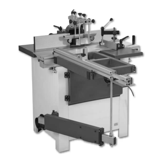
- Page 1 Code: 501209 WS1000TA Spindle Moulder Axminster Tool Centre, Unit 10 Weycroft Avenue, Axminster, Devon EX13 5PH www.axminster.co.uk...
-
Page 2: Table Of Contents
Index of Contents Page No. Index of Contents Declaration of Conformity What’s Included 03-04-05-06 Optional Accessories General Instructions for 230V Machines 06-07 Specific Safety Precaution 07-08 Specifications Assembly 09-10-11-12-13-14-15-16 Illustration and Parts Description 17-18-19-20-21 Setting Up the Machine 22-23 Installing/Changing the Spindle Moulder Cutter Changing the Spindle Moulder Speed Positioning the Machine Using a Sanding Drum... -
Page 3: Optional Accessories
What’s Included Quantity Item Model Number 1 off Spindle Moulder MX5110A Support Table Assembly 1 off Support Table 2 off Lift & Shift Handles with Washers (M8 Thread) 1 off Pre-drilled Steel Plate Spindle Guard Assembly 1 off Spindle Guard with Adjustable Fence 2 off Lift &... - Page 4 What’s Included...
- Page 5 What’s Included...
-
Page 6: General Instructions For 230V Machines
What’s in the Box General Instructions for 230V Machines Good Working Practices/ Safety The following suggestions will enable you to observe good working practices, keep yourself and fellow workers safe and maintain your tools and equipment in good working order. WARNING! KEEP TOOLS AND EQUIPMENT OUT OF THE REACH OF YOUNG CHILDREN! Mains Powered Tools... -
Page 7: Specific Safety Precaution
General Instructions for 230V Machines KEEP THE WORK AREA AS UNCLUTTERED AS IS PRACTICAL. UNDER NO CIRCUMSTANCES SHOULD CHILDREN BE ALLOWED IN WORK AREAS. It is good practice to leave the machine unplugged are liable to be a ‘snag’ hazard. Consideration should until work is about to commence, also make sure to also be given to non-slip footwear, etc. -
Page 8: Specifications
Keep work area well lit. Remove all loose clothing and enclose long hair. Before operating the machine, remove tie, rings, watches, other jewellery, and roll up sleeves above elbows. Specifications Model WS1000TA Product Code 501209 Rating Trade Power 2.8kW (230V, 1ph) - Page 9 Having unpacked the boxes, (please dispose of any unwanted packaging responsibly), put the parts and Note: The WS1000TA spindle moulder comes 95% components whereby they are readily to hand. Break assembled, in order to reduce the footprint of the...
- Page 10 Assembly Line up the edge of the steel plate (C3) with the ‘T’ slot machined into the sliding table A see fig 3. Slide the support table assembly (C) onto the sliding table & position it to the far side. Tighten the two lift and shift handles (C2) to clamp the assembly in position (See fig 4).
- Page 11 Assembly Fig 7 Fig 8 Nuts & washers Fig 9 Fig 10 ‘T’ slot Machined slots Fig 11 Fig 12 Pre-drilled holes Pins Fig 13 Fig 14...
- Page 12 Assembly Fig 15 Fig 16 Straght edge Adjustment screw 5mm Allen Key Locate the two M6 x 11mm caphead screws (B5), line up the extention table support rod (B7) bracket with the pre-drilled holes in the extention table (B1), using the two M6 caphead screws and a 5mm allen key secure the support rod (B7) to the table (B1) (See fig 15).
- Page 13 Assembly 90˚ Stop Fig 19 Fig 20 Fig 21 Fig 22 Lift & shift handle pin lock Turning the handle to Turn butterfly knob to lock pin lock the fence Step 3 Spindle Guard Assembly Locate the spindle guard (D1) and the two M8 x 140mm lift & shift handles with washers (D2). Raise the spindle to the maximum height by unlocking the spindle moulder rise/fall locking handle (a) and turning the spindle moulder rise/fall wheel clockwise (b) then lock in place (See figs 23-24).
- Page 14 Assembly Circular rings Fig 25 Fig 26 Fig 27 Fig 28 Locate the guide assembly mounting bracket (D3), using a 6mm allen key remove the four caphead bolts & washers on top of the spindle guard (D1), place safely aside (See fig 29). Lower the guide assembly mounting bracket (D3) on top of the spindle guard &...
- Page 15 Assembly Step 4 Guide Assembly Locate the guide arm (E1) and slide it through the mounting bracket (D3), with two thirds extending out for the front of the guard, clamp in place using the M8 clamping knob (E2) and lift and shift handle (E3) (Se e figs 31-32). Locate the feeder roller assembly (E4) and slide it onto the guide arm (E1), clamp in place using the clamping knob (See fig 33).
- Page 16 Assembly Step 5 Mi tre Fence Work Clamp Assembly Locate the pre-drilled metal plate (F3) & slot it into the machined ‘T’ slot in the sliding table (See figs 35-36). Lower the mitre fence casting (F1) on top of the metal plate (F3), line up the machined slot & pre-drilled hole in the mitre fence casting with the holes in the metal plate, see fig 37, locate the M10 clamping knob (F4) with washer &...
- Page 17 Illustration & Parts Description A Spindle Moulder D Spindle Guard Assembly B Sliding Table Extention Assembly Optional E Guide Assembly Accessory (Order No: 950505) F Mitre Fence Work Clamp Assembly C Sliding Bench Assembly...
- Page 18 Illustration & Parts Description E5 Anti-kickback assembly E4 Guide roller assembly F2 Work clamp Mitre fence F5 Lift & shift D1 Spindle guard with handle adjustable fence Sliding table Work table handle Sliding table C1 Steel bench B1 Extension table casting B2 Extension table fence Motor...
- Page 19 Illustration & Parts Description Guide roller E2 Clamping knob clamping knob E3 Lift & shift handle Anti-kickback clamping knob E1 Guide arm Guide roller height D3 Guide assembly bracket clamping knob Anti-kickback height D2 Lift & shift handle clamping knob Fence advancing knob Fence adjusting...
- Page 20 Illustration & Parts Description Fig 41 Fig 42 Spindle moulder control panel NVR ON/OFF switch Fig 43 Fig 44 Reversing selector switch Emergency stop shroud, slap the shroud down to stop the machine. NOTE: The machine is equipped with a FORWARD/REVERSE switch as shown in figure 43. You will find many instances that it is necessary to flip the cutter over and reverse the cutter rotation.
- Page 21 Illustration & Parts Description Fig 47 Fig 48 The extension table fence set to 45˚ Extension table angle scale Magnifying glass Butterfly clamping knob Fig 49 Fig 50 Distance stop clamp Distance stop assembly Telescopic extension assembly Fig 51 Fig 52 Spindle moulder table height Sliding table height adjusting nuts (b) adjusting nuts (a)
-
Page 22: Setting Up The Machine
Setting Up the Machine Setting the fence The fence is a two piece adjusting system. Each fence is independently adjustable to compensate for different cutting thicknesses. Make sure the fence is square to the work surface, place a 90˚ square up against the fence and check it is perpendicular to the work surface. -
Page 23: Fig 59
Setting up the Machine Fig 59 Adjusting the feeder roller & ant-kickback assembly Loosen the feeder roller clamping knobs (a and b) & move the feeder roller to the centre of the workpiece, tighten the clamping knobs. Undo the anti-kickback clamping knobs (c and d) and move the assembly near the workpiece, tighten the clamping knob (c), raise the assembly so the steel plate is about 5-10mm above the work table (See figs 60 &... -
Page 24: Fig 64
Installing/Changing the Spindle Moulder Cutter DISCONNECT THE MACHINE FROM THE MAINS SUPPLY! Raise the spindle to the maximum height by unlocking the spindle moulder rise/fall locking handle and turning the spindle moulder rise/fall handle clockwise then lock in place. Using a 19mm spanner remove the bolt & clamping block (D), spacing collar/s (E) and clamping washer (F) and place them safely aside, remove the cutter block. -
Page 25: Fig 68
Changing the Spindle Moulder Speed DISCONNECT THE MACHINE FROM THE MAINS SUPPLY! Open the motor access door to the front of the machine, by removing the two caphead screws, see figs 68 & 69, lower the spindle to it’s lowest point, if not done so already. Locate the 10mm allen key (G), loosen the caphead bolt (H) on top of the motor, pull the motor tension lever (I) out, to allow the belt to go slack &... -
Page 26: Positioning The Machine
The machine should be positioned on a flat level surface. Once the machine is in position, and level, it can be bolted to the floor if so required. SAFETY WARNING! The WS1000TA Spindle 218kg Moulder is a heavy piece Max Weight of equipment. -
Page 27: Using A Sanding Drum
Using a Sanding Drum Sanding drum assembly Fig 73 Operating Instructions Workpiece Handling •Feed the workpiece straight across the machine table, holding the fingers close together and guiding the workpiece with the palms of your hands. •Never put your hands under or behind the cutter guard. •Always keep your hands well clear of the rotating cutter. -
Page 28: Optional Accessories
Optional Accessories The spindle moulder can be fitted with the following A medium weight power feed unit with three white optional accessories: rubber rollers, all spring-loaded to provide a constant feed rate on either a planer, saw bench or spindle •... -
Page 29: Routine Maintenance
If you find that the machine is not performing as it should please contact “Axminster... -
Page 30: Trouble Shooting
Trouble Shooting DISCONNECT THE MACHINE FROM THE MAINS SUPPLY! -
Page 31: Wiring Diagram
Wiring Diagram... - Page 32 Parts List/Drawings...
-
Page 33: Parts List
Parts List/Drawings... - Page 34 Parts List/Drawings...
- Page 35 Parts List/Drawings...
- Page 36 Parts List/Drawings...
- Page 37 Parts List/Drawings...
- Page 38 Parts List/Drawings...
- Page 39 Parts List/Drawings...
- Page 40 Parts List/Drawings...
- Page 41 Parts List/Drawings...
- Page 42 Parts List/Drawings...
- Page 43 Parts List/Drawings...
- Page 44 Please dispose of packaging for the product in a responsible manner. It is suitable for recycling. Help to protect the environment, take the packaging to the local recycling centre and place into the appropriate recycling bin. Only for EU countries Do not dispose of electric tools together with household waste material.
Need help?
Do you have a question about the WS1000TA and is the answer not in the manual?
Questions and answers