
Related Manuals for Axminster ujk 106843


Summary of Contents for Axminster ujk 106843
- Page 1 Code 106843 Universal F I N D O U T M O R E Dovetail Jig BOX / FINGER JOINTS THROUGH DOVETAILS HALF BLIND DOVETAILS GROOVE / HOUSING JOINTS SLIDING DOVETAILS CORNER DOVETAIL REBATES AT: 22/03/2021...
-
Page 2: Table Of Contents
All copyright, design rights and Intellectual property rights in our designs and products are, and will remain, the property of Axminster Tool Centre Ltd. We treat any infringements of these rights seriously. Axminster Tool Centre Ltd is a member of ACID. -
Page 3: Anatomy
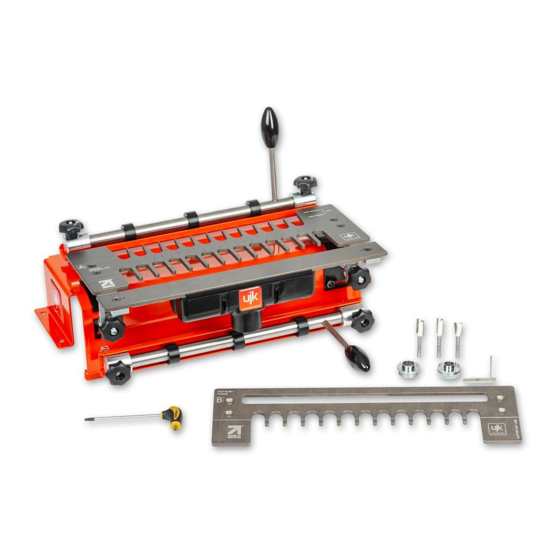
ANATOMY ‘Side Stop’ repositioned to support extraction nozzle when using Template B for ‘Sliding Dovetail’ joints. Horizontal clamp handle Comb Through Dovetail / Box Template A Horizontal cam clamp Comb support Dovetail mounting bracket Magnetic extraction Vertical cam clamp Router Vertical clamp extraction handle... -
Page 4: Dovetail Jig Assemby & Setup
DOVETAIL JIG ASSEMBLY & SETUP Assembly Comb Template Lower the comb template down & line up the counter- sink holes with the holes in the comb bar support arms (C). Secure in place using four countersink Hex screws (I) - Page 5 DOVETAIL JIG ASSEMBLY & SETUP Mounting the Jig Router Cutter Mount the jig onto a firm and stable workbench at a Supplied with three Axcaliber 1/4” shank cutters, comfortable height, remembering that the router sits on (7˚dovetail/ straight), see fig C. You can also purchase top of the jig.
-
Page 6: Half Blind Dovetails
HALF BLIND DOVETAILS Fig 04 • Max timber width - 300mm • Min timber thickness - 13mm • Max timber thickness - 25mm Parts needed - • Template B (half blind / sliding) • 13.55mm Dovetail cutter 3) Load in vertically the first board on the left of the jig •... - Page 7 HALF BLIND DOVETAILS Fig 08-09-10 Fig 14-15-16 Guide line 7) Remove both boards & try for fit. If the joint is too tight & won’t fit together with a light tap then raise the cutter very slightly (approx 0.5mm) and recut new boards, see fig 17.
-
Page 8: Groove / Housing Joints
GROOVE / HOUSING JOINTS Fig 03-04-05 Square Line • Max timber width - 290mm • Min timber thickness - 10mm • Max timber thickness - 25mm Parts needed - • Template B (sliding / half blind) • Any straight cutter up to 14.5mm in diameter •... - Page 9 GROOVE / HOUSING JOINTS Fig 09 Magnetic extraction 4) The cutter size will generally match the board to be 6) Start the cut at the right hand side of the jig moving slotted into the routed groove (eg 10mm board = 10mm the router from right to left, see fig 15-16.
-
Page 10: Sliding Dovetails
SLIDING DOVETAILS Fig 05-06-07-08 • Max timber width - 290mm • Min timber thickness - 13.5mm • Max timber thickness - 25mm Parts needed - • Template B (sliding / half blind) • Dovetail cutter • ¾” (19mm) Guide bush Dovetail slot boards are cut horizontally, the opposing tenon boards are cut vertically 3) Ensure that the comb is sat flat &... - Page 11 SLIDING DOVETAILS NB if working in very hard wood a stock removal cut may be wise, this is done by running a 6mm cutter through the slot first, with the cut depth a little less than the required dovetail cut, see fig 13-14. Fig 13-14 4) With the cutter set at the same depth as when cutting the dovetail slot (approx ⅔...
-
Page 12: Through Dovetails
THROUGH DOVETAILS Fig 03-04-05 Side Stop • Max timber width - 300mm • Min timber thickness - 10mm • Max timber thickness - 19mm (pin board) 25mm (tail board) Parts needed - Fig 06-07 • Template A (through / box) •... - Page 13 THROUGH DOVETAILS Fig 10-11 Fig 19-20 6) Slide or reattach the extraction, see fig 12 on the right & begin the cut working from left to right ensuring that the router stays flat on the comb at all time, see fig 13. Use the guide lines to help find the fingers, see fig 14 DO NOT LIFT THE ROUTER WHILST IT IS RUNNING! Fig 12-13-14...
- Page 14 THROUGH DOVETAILS Fig 25-26-27 Trouble shooting - • Joint too tight - move comb backwards & recut • Joint too loose - move fingers forward & recut new board • Gaps at one end of the joint - timber not square, comb not sat flat on timber, see fig 31 •...
-
Page 15: Box / Finger Joints
BOX / FINGER JOINTS Fig 03-04-05-06 Side Stop • Max timber width - 300mm • Min timber thickness - 6mm • Max timber thickness - 25mm Parts needed - • Template A (through / box) • 12.5mm Straight cutter • ¾” (19mm) Guide bush All boards are cut vertically 1) Attach comb A with the straight fingers at the front of the jig, see fig 01 &... - Page 16 BOX / FINGER JOINTS Fig 11-12-13 6) Slide or reattach the extraction & begin the cut working from left to right ensuring that the router stays flat on the comb at all times, see fig 14. Use the guide comb lines to help find the fingers, see fig 15. DO NOT 8) Slide side stop to the left to make contact with the LIFT THE ROUTER WHILST IT IS RUNNING! board &...
-
Page 17: Corner Dovetail Rebates
BOX / FINGER JOINTS 10) Cut from left to right at a slow steady pace & check Fig 26 for fit, see fig 24 Fig 24 Fig 27 Trouble shooting - • Box sides not in line - timber not centralised or timber not cut equally, see fig 25. - Page 18 CORNER DOVETAIL REBATES Fig 03-04 Fig 09-10 5) Start the cut at the right hand side of the jig moving the router from right to left in a slow, steady, continuous motion, see fig 11 DO NOT LIFT THE ROUTER AT ANY TIME DURING A CUT, see fig 12-13. Fig 11-12-13 3) Mark an 8mm line from the top edge on the side of the vertical board, see fig 05 then load in the vertical...
- Page 19 CORNER DOVETAIL REBATES 3) Use the wider part of the set gauge to position board edge to the centre of the comb slot, see fig 25-26. NB - The cutter will need to be loaded in through the Fig 25-26 base of the router with the ⅝"...
- Page 20 3) Start the cut at the right hand side of the jig moving the router from right to left in a slow steady continuous motion DO NOT LIFT THE ROUTER AT ANY TIME DURING A CUT, see fig 37. Axminster Tool Centre Ltd, Axminster, Devon EX13 5PH axminstertools.com/ujk...
Need help?
Do you have a question about the ujk 106843 and is the answer not in the manual?
Questions and answers