
Related Manuals for Axminster SIEG Super X2 Mill


Summary of Contents for Axminster SIEG Super X2 Mill
- Page 1 SIEG Super X2 Mill A X M I N S T E R W H I T E 2007 Axminster Reference No: Super X2 w w w. a x m i n s t e r. c o . u k...
-
Page 2: Table Of Contents
Index of Contents... Page No. Index of Contents..........................01 Declaration of Conformity………….………..……..…………..........02 What’s in the Box………….………..……..…………..............03 General Instructions for 230v Machines................04 Basic Safety for Machine Tools................... 05-06 Specifications….………..……..…………...................06 Definitions............................07 Initial Assembly..........................07 Parts Description......................... 08-09 Parts Illustration & Description....................10-11-12 Operating Instructions......................13-14-15 Collet Chuck Assembly (Optional)................ -
Page 3: Declaration Of Conformity
Declaration of Conformity... Copied from CE Certificate The undersigned, authorised by Shanghai SIEG Machinery Co., Ltd. No.555 Caofeng Rd. South to No.17 Bridge of Caoan Rd. Shanghai, P.R. China declares that this product: MILLING MACHINE manufactured by Shanghai SIEG Machinery Co. is in compliance with the following standards or standardisation documents in accordance with Council Directives... -
Page 4: What's In The Box
Having unpacked your machine and its accessories, please check the contents against the equipment list "What’s in the box", if there are any discrepancies, please contact Axminster Power Tool Centre using the procedures laid down in the catalogue. Please dispose of the packaging responsibly, much of the material is bio-degradable. -
Page 5: General Instructions For 230V Machines
General Instructions for 230v Machines... Good Working Practices/Safety The following suggestions will enable you to observe good working practices, keep yourself and fellow workers safe and maintain your tools and equipment in good working order. KEEP TOOLS AND EQUIPMENT OUT WARNING!! OF THE REACH OF YOUNG CHILDREN Mains Powered Tools... -
Page 6: Basic Safety For Machine Tools
Basic Safety for Machine Tools... KNOW YOUR MACHINE TOOL Read and understand the owner's manual and labels affixed to the tool. Learn its application and limitations as well as specific potential hazards peculiar to the tool. KEEP GUARDS IN PLACE Keep all guards in place. -
Page 7: Specifications
NEVER operate tools whilst under the influence of drugs, alcohol or after taking medication. USE THE CORRECT TOOL Do not force a tool or attachment to do a job for which it was not designed. This is dangerous workshop practice. Specification... Axminster No. 600858 (Super X2) Motor: Input 230V 50Hz 750W Motor Output:... -
Page 8: Definitions
Definitions... ‘X’ Axis. This is the axis described by the work table as it is moved side to side. Normally, movement that moves the tool to the right in the workpiece is referred to as +ve ‘X’, and movement that moves the tool to the left in the workpiece is referred to as –ve ‘X’. -
Page 9: Parts Description
Parts Description... Base casting This is the stand for the milling m/c. It is a square casting with a seated flange to the rear, which mounts the main tool post. There are four holes to each corner to be bolted to a bench or stand. There is a dovetail slide machined to the front service of the base, to mount the traverse slide of the work table. - Page 10 Parts Description... Milling head This is the ‘milling machine’ and the descriptions of its various parts and components are detailed as follows:- Milling head The main casting to which all the components are attached. The head has a casting dovetail housing machined at the rear, which allows the casting to be fitted to the Main Tool Post.
-
Page 11: Parts Illustration & Description
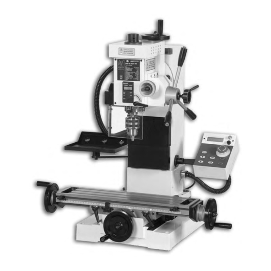
Parts Illustration & Description... Tilt housing Draw bar Typ. 3 Spindle automatic return Scale button Tri-lever feed Fine feed handle control knob (see page 14) D.R.O control (see page 13) Fine feed clutch knob Guard Pointer Fig 1 Control panel Work table (see page 12) Chuck... - Page 12 Parts Illustration & Description... Rise and fall handle Typ.2 Rise and fall clamps Tool post Fig 2 Typ. 6 Rise and fall gib strip adjusters Spindle lock handle Tool tray Main tool post Traverse slide clamps Traverse slide thimble Traverse slide gib strip adjusters...
-
Page 13: Parts Illustration & Description 10
Parts Illustration & Description... 10mm nut Rise & fall thimble Fig 3 90˚ Locking pin assembly Traverse slide stop Tilt housing clamps, two on each side of the milling head. -45˚ +45˚ Fig 4 Tilt housing assembly... -
Page 14: Operating Instructions
Operating Instructions... Control Panel 1. Make sure the correct fuse is in the fuse box and the power switch is off. Unlock the emergency stop button, connect the machine to mains and switch on. The power light on the control panel will come on. 2. - Page 15 Operating Instructions... D.R.O. Control Digital Read Out (DRO) (Fig 5) For normal drilling operations press the ON/OFF switch first, and then press the “ZERO” button. Press “mm/in” button to select metric or imperial readings. These two buttons can be effected regardless of the down feed handle position, then you can start drilling.
- Page 16 Operating Instructions... Engaging the fine feed control 1) Turn the fine feed clutch knob clockwise until it becomes tight (DO NOT OVERTIGHTEN), thus engaging the fine feed control mechanism (See fig 6). 2) Turn the fine feed control knob to lower or raise the spindle in gradual movements (See fig 7). 3) To disengage the fine feed control turn the clutch knob anti-clockwise until it is loose.
-
Page 17: Collet Chuck Assembly (Optional)
Collet Chuck Assembly (Optional)... The chuck can be removed and replaced with an optional collet chuck for milling operations. Please fol- low the instruction below for chuck removal. DISCONNECT THE MACHINE FROM THE MAINS SUPPLY 1) Unscrew the draw bar cover and safely put to one side (See fig 8). Turn the spindle lock handle clockwise to lock the spindle. -
Page 18: Maintenance
Collet Chuck Assembly (Optional)... Fig 13 4) Insert the collet chuck into the spindle taper and screw it onto the arbor shaft. Hold the collet chuck, using an adjustable or ‘C’ spanner (See fig 13). Insert the 8mm hex key into the recess on top of the arbor as shown in figs 8 &... - Page 19 Maintenance... Worktable and Traverse feed adjustment The worktable and the traverse feed are both mounted over dovetail sections. In order to maintain the ‘tightness’ of the fit; between the sloping surface of the component and its mating surface a gybe strip has been inserted. (At the front of the worktable, and to the left hand side of the traverse feed).
- Page 20 6. Wipe the quill outer sleeve clean and lightly oil, exercise the quill to spread the oil in the sleeve bushes. Monthly a) Give the motor a good ‘blow through’ to remove any dust, dirt etc. b) Check all the interlocks function correctly. Accessories There are numerous accessories for the machine listed in the Axminster catalogue.
-
Page 21: Troubleshooting
Troubleshooting... - Page 22 Troubleshooting...
-
Page 23: Parts Breakdown Part 1,2,3
Parts Breakdown Part 1... - Page 24 Parts Breakdown Part 2...
- Page 25 Parts Breakdown Part 3...
-
Page 26: Parts List
Parts List... - Page 27 Parts List...
- Page 28 Parts List...
- Page 29 Parts List...
- Page 30 Parts List...
-
Page 31: Notes
Notes... - Page 32 Axminster Reference No: Super X2 A X M I N S T E R W H I T E Axminster Devon EX13 5PH UK FREEPHONE 0800 371822 www.axminster.co.uk 2007...
Need help?
Do you have a question about the SIEG Super X2 Mill and is the answer not in the manual?
Questions and answers