
Related Manuals for Axminster PROFESSIONAL AP50UE


Summary of Contents for Axminster PROFESSIONAL AP50UE
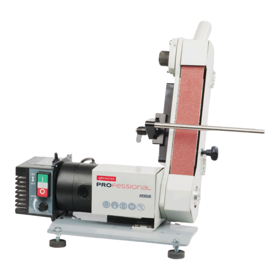
- Page 1 Code 107658 Original Instructions AP50UE Ultimate Edge Variable Speed Sharpening System Code 106686 Ultimate Edge Angle Gauge Included AT: 20/04/2022 BOOK VERSION: 7...
-
Page 2: Eu Declaration Of Conformity
Exploded Diagrams/List 24-25-26 Wiring Diagram Spindle Speed Digital Readout Troubleshooting EU DECLARATION OF CONFORMITY Cert No: DC-P50 EU Declaration of Conformity Axminster Tool Centre Ltd This machine complies with the following directives: Axminster Devon EX13 5PH UK axminstertools.com 2006/42/EC 2014/35/EU... -
Page 3: What's Included
WHAT’S INCLUDED Model Number AP50UE Quantity Item Part Ultimate Edge Variable Speed Sharpening System Abrasive Belt (Fitted) Adjustable Rubber Feet Graphite Pad (Self Adhisive) Long Hex Key 4mm Ultimate Edge Angle Gauge Code 103738 Support Bar with Dual Axis Adjustment •... -
Page 4: General Instructions For 230V Machines
GENERAL INSTRUCTIONS FOR 230V MACHINES The following will enable you to observe good working • Carry out a final check to the machine. practices, keep yourself and fellow workers safe and maintain your tools and equipment in good working order. •... - Page 5 ASSEMBLY Fig B Fig 03-04-05 Lock Unlock Press knob in and twist Control box assembly Threaded Rubber Feet Locate the four ‘Rubber Feet’ (C), remove one nut from each of the threaded feet and place aside. Slot each threaded foot through the four pre-drilled holes to each corner of the unit’s base.
- Page 6 ASSEMBLY Fig 06-07 3. Remove the belt and place safely aside, see fig 09. Fig 09 There are two options that can be fitted to the ‘Platen’ . • The ‘Platen’ on its own • The ‘Graphite Pad’ which is included Fig 08 For most applications we recommend the fitting of the graphite pad ,the graphite pad has a self adhesive backing and is stuck...
- Page 7 ASSEMBLY Fig 10-11-12 5. Slide the belt back on and centre the belt on the platen. Press the lever (2) down and hold in place, pull the locking ‘PIN’ (3) out and raise the platen to re-tension the belt, see fig 13. 6.
-
Page 8: Illustration & Parts Description
ILLUSTRATION & PARTS DESCRIPTION 32mm Upper dust extraction outlet Belt tension mechanism Belt Guard Locking pin Belt tracking knob Motor brush access cap Main ON/OFF switch Belt door Belt Locking knob 32mm Lower dust Motor Work table extraction outlet Control box Base plate Motor brush cap Adjustable rubber foot... - Page 9 ILLUSTRATION & PARTS DESCRIPTION Locking pin for tension mechanism (A), Tracking control knob Belt tension mechanism (B), Operating lever (C) to release the tenstion to the belt 32mm Lower dust extraction outlet (F) Foward/Reverse selector switch Belt speed (MPM) Meters Per Minute ON/OFF buttons Speed control dial Main ON/OFF switch...
- Page 10 SETUP/ADJUSTMENT Tracking the Belt CONNECT THE MACHINE TO THE MAINS SUPPLY! Switch ON 1. Press the main ON/OFF on switch to the ‘ON’ position, see fig 21. 2. Move the selector switch to the ‘Forward’ position, see fig 22. 3. Make sure the speed control dial is turned right down then press the ‘GREEN’...
- Page 11 SETUP/ADJUSTMENT Setting the Platen Angle 5. Turn the ‘Tracking Knob’ until the belt is centred on the platen, see fig 27-28-29. The platen can be pivoted to the required angle by loosening the two button Hex screw, see fig 31. Lower the platen to the NOTE: Don’t make sudden adjustments otherwise you required angle, see fig 32.
-
Page 12: Changing The Belt
CHANGING THE BELT DISCONNECT THE MACHINE FROM THE MAINS SUPPLY! Remove old belt Clean inside the drive belt assembly... - Page 13 CHANGING THE BELT Press down the lever and hold in place, pull the locking pin out and raise the roller assembly to re-tension the belt. Press down Pull locking pin Replace the belt and close the door. CHANGING MOTOR BRUSHES/ MAINTENANCE Check the condition of the motor brushes every 5-6 months.
- Page 14 SUPPORT BAR WITH DUAL AXIS ADJUSTMENT Support Bar Assembly Slot the bolt (B) through the elongated slot in the adjustable mounting plate (G). Position the plate (G) against the platen, line up the four holes, secure in position using the screws (C) &...
- Page 15 SETTING THE SUPPORT BAR Terminology of the Support Bar These are the striations, Support Bar we call them sharpening lines Loosen the two studs Platen Back Left Right Down Front Platen Grub screw B Grub screw A Grub screw C Grub screw D 0.5 to 1mm Clearance...
- Page 16 SETTING THE BAR TO THE PLATEN Method One Method Two Alternatively place a 90˚ square on the bar and check its in line Setting the Bar at 90˚ to the Platen with the edge of the platen and make adjustments accordantly. Linisher Square to the platen Using a digital leveling box check the suport bar is perpendicular...
- Page 17 ULTIMATE EDGE ACCESSORIES Axminster Honing Guide Assembly (code 105281) Universal Edge Gauge Setting (code 103730) As with all accurate sharpening, it’s all about the angles and our 18 piece set gives all angles from 90° through to 5°. The set is perfect for setting up sharpening guides as well as The Ultimate Edge Honing Guide is perfect for plane blades, checking ground angles.
- Page 18 White Super Fine Paste 103716 Flame Retardant Extraction Hose 25mm x 2m 103717 Axminster Profiled Honing Wheel Code 104737 Many of the Tormek® jigs work amazingly well on the 12mm bar of the Ultimate Edge and provide the user with extremely sharp and accurately ground tools.
- Page 19 Axminster Polishing and Honing Accessories A variety of 12mm bore accessories are available for use on the “Twist n Fix” 12mm arbor including a leather profiled wheel for carving tools, a rubberised wheel for polishing and traditional mops both stitched, loose leaf and sisal.
- Page 20 ULTIMATE EDGE ACCESSORIES Screw on the mop/honing wheel (not supplied) Detach assembly Mount the carrier using the three Hex Insert the tommy bars into screws the holes in the “Twist n Fix” assembly and tighten the Line up the bayonet fitting with the carrier pins, press in and ‘Twist’...
- Page 21 & Honing Paste 250g & Honing Paste 250g Polishing & Honing Paste 250g Code 103703 Code 103715 Code 103716 Acrylic Polish Axminster Yellow Polishing Compound Axminster Blue Polishing Compound Code 105761 Code 105921 Code 105924 Axminster Pink Polishing Compound Axminster Brown Polishing Compound...
- Page 22 POLISHING COMPOUND CHART...
-
Page 23: Other Accessories
This adaptor enables the 32mm Flame Retardant Extraction The all-steel container has a 25mm adaptor. Please note this Hose (106624) used to extract from the Axminster Trade extractor must be used with suitable heat resistant hose such Ultimate Edge Sharpening Machine to connect to the Numatic as product code 106624. - Page 24 EXPLODED DIAGRAMS/LIST...
- Page 25 EXPLODED DIAGRAMS/LIST PART NO DESCRIPTION SPECIFICATION MOTOR CORD CONTROL BOX MOTOR ROUND HEAD #10-24*5/16” BASE PLATE SCREW FOOT PAD STRAIN RELIEF 6P-4 3/8” BUSHING SPRING #10-24 WASHER VR KNOB BUTTON HEAD M8X12 ROUND HEAD M3X20MM SCREW SHEET METAL MOTOR PLATE SCREW FLAT HEAD M5X12...
-
Page 26: Wiring Diagram
EXPLODED DIAGRAMS/LIST BODY COVER STOP ROD ROUND HEAD M5X6 HANDLEBAR SCREW SPRING SIDE COVER COVER MOTOR LABLE WASHER I.D LABLE 02X12 WARNING BUTTOM M3X10 LABLE SCREW GRAPHITE PAD WASHER POM SET NYLON NUT SCREW LOCK HANDLE SET SCREW M6X15 WEAR PLATE BUTTOM HEAD M6x10 LONG REACH... - Page 27 SPINDLE SPEED DIGITAL READOUT TROUBLESHOOTING On occasions the spindle speed D.R.O may display error message codes. If your machine stops unexpectedly and shows an error code, look at the table below to determain what the code means and how to resolve the issue. ERROR Description Solution...
- Page 28 The packaging is suitable for recycling. Please dispose of it in a responsible manner. EU Countries Only Do not dispose of electric tools together with household waste material. By law they must be collected and recycled separately. Axminster Tools, Axminster Devon EX13 5PH axminstertools.com...
Need help?
Do you have a question about the PROFESSIONAL AP50UE and is the answer not in the manual?
Questions and answers