Table of Contents
Advertisement
Quick Links
Advertisement
Table of Contents

Related Manuals for Axminster Router Elevator


Summary of Contents for Axminster Router Elevator
- Page 1 Axminster Router Elevator w w w. a x m i n s t e r. c o . u k...
-
Page 2: Table Of Contents
Router Elevator Parts Drawing....................14 Router Elevator Parts List......................15 Copyright... This product has been wholly designed by Axminster Power Tool Centre Ltd who have exclusive use of the design. As such it should not be copied or reproduced. The symbols shown on the cover of this... -
Page 3: What's In The Box
What’s in the Box... Model Number: 210081 1 No. Axminster Router Elevator (with router mounting plate and Table Insert fitted) 1 No. Winding Handle 1 No. Floating Measurement Dial 1 No. Packet containing:- 6 No. M6 Grub Screws 2 No. M6 Countersunk Bolts 1 No. -
Page 4: Specifications
Having unpacked your machine and its accessories, please check the contents against the equipment list ”What’s in the box”, if there are any discrepancies, please contact Axminster Tool Centre using the procedures laid down in the catalogue. Please dispose of the packaging responsibly;... -
Page 5: Accessories
(410197) to be mounted to the assembly. These scales also have the provision to accept the Single Axis Remote Reader (210068). The machine table has been prepared to allow for the mounting of the Axminster Box Comb Jointer (Part No.700308). Machine table hard point Rise &... -
Page 6: Dimensions/Position Diagram
Dimensions/Position Diagram... Fig A www.axminster.co.uk... -
Page 7: Parts Description Of The Router Elevator
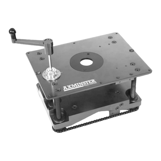
Parts Description of the Router Elevator... Machine table This is a 6mm alloy plate 306mm x 229mm, which mounts the threaded corner pillars and the rotating guide for the winding handle. In each corner of the plate there is a threaded M6 hole into which the supplied grub screws can be inserted to enable the table to be levelled (if the recess is not quite perfect?). -
Page 8: Illustration & Description Of The Router Elevator
Illustration & Description of the Router Elevator... Grub screw hole for levelling function Reference marker for the floating 38mm Table insert measurement dial Box comb jointer Typ. 2 grub screw Winding handle mounting holes holes for support Machine table functions... - Page 9 Illustration & Description of the Router Elevator... Nippled ‘Y’ wrench Lock Un-lock Table insert sprockets Hard point to mount Drive sprocket the digital read out Chain Universal router Typ. 4 clamping lugs Idler sprocket mounting plate...
-
Page 10: Set Up/Operating Instructions
Ensure you have identified all the parts of your Router Elevator. Place the Router Elevator into the prepared recess. See Fig A on page 06. Check that it is flush with the work platform surface. If this is not the case insert the supplied grub screws in the threaded corner holes and level the machine table. - Page 11 Allen Key Fig 3 Fig 4 Fitting the mounting plate to the router Removing the base plate from the router Router/mounting plate mounted in the router elevator Please note: Removing the router handles will prevent Fig 5 them from interfering with...
-
Page 12: Fitting The Accessory Digital Readout Scale
Using the same two screws loosely fasten the clamping plate to the hard point on the machine table of the router elevator, See Fig 8. Insert the end of the digital scale into the pocket created by the hard point and the clamping plate, set it as square as possible and clamp it in position by tightening the two screws. -
Page 13: Maintenance
(210068) whereby you can place the relayed digital readout where it is most convenient. Maintenance... The router elevator requires minimum maintenance, but you are advised to observe the following points:-. 1. Keep the elevator clean. Ensure that dust/chips etc., are cleaned away at the end of a work session. -
Page 14: Router Elevator Parts Drawing
Router Elevator Parts Drawing... -
Page 15: Router Elevator Parts List
Router Elevator Parts List... 0800 371822 FREEPHONE... - Page 16 Axminster Devon EX13 5PH UK FREEPHONE 0800 371822 www.axminster.co.uk...
Need help?
Do you have a question about the Router Elevator and is the answer not in the manual?
Questions and answers