Intel SR1500AL - Server System - 0 MB RAM User Manual
Server system
Hide thumbs
Also See for SR1500AL - Server System - 0 MB RAM:
- Specification (42 pages) ,
- Manual (87 pages)
Table of Contents
Advertisement
Quick Links
Download this manual
See also:
Manual
Advertisement
Table of Contents

Related Manuals for Intel SR1500AL - Server System - 0 MB RAM


Summary of Contents for Intel SR1500AL - Server System - 0 MB RAM
- Page 1 ® Intel Server System SR1500AL User’s Guide A Guide for Technically Qualified Assemblers of Intel® Identified Subassemblies/ Products Intel Order Number D31970-002...
- Page 2 Intel products are not designed, intended or authorized for use in any medical, life saving, or life sustaining applications or for any other application in which the failure of the Intel product could create a situation where personal injury or death may occur.
- Page 3 ® Intel Server System SR1500AL User’s Guide...
- Page 4 § ® Intel Server System SR1500AL User’s Guide...
-
Page 5: Preface
BIOS Setup screens, how to perform a BIOS update, and how to reset the password or ® CMOS. Information about the specific BIOS settings and screens is available in the Intel 5000 Series Chipsets Server Board Family Datasheet. See “Server System References”... -
Page 6: Intel ® Server System Sr1500Alsas Contents
® There are two versions of this server system: the Intel Server System SR1500ALSAS ® (SAS/SATA version) and the Intel Server System SR1500AL (SATA only version). The contents of each server system are listed below. ® Intel Server System SR1500ALSAS Contents ®... -
Page 7: Intel ® Server System Sr1500Al Contents
® Intel Server System SR1500AL Contents ® Your Intel Server System SR1500AL ships with the following items: ® • Intel Server Board S5000PAL, installed in the server system • One 600 W power supply module, installed in the server system •... - Page 8 ® viii Intel Server System SR1500AL User’s Guide...
-
Page 9: Safety Information
Safety Information Important Safety Instructions Read all caution and safety statements in this document before performing any of the instructions. See also Intel Server Boards and Server Chassis Safety Information on the ® Intel Server Deployment Toolkit 2.0 CD and/or at http://support.intel.com/support/... - Page 10 重要安全指导 在执行任何指令之前,请阅读本文档中的所有注意事项及安全声明。 和/或 上的 Intel http://support.intel.com/support/motherboards/server/sb/CS-010770.htm Server Boards and Server Chassis Safety Information(《Intel 服务器主板与服务器机箱安全信息》)。 ® Intel Server System SR1500AL User’s Guide...
- Page 11 Take care to grip with, but not squeeze, the pliers or other tool you use to remove a jumper, or you may bend or break the pins on the board. ® Intel Server System SR1500AL User’s Guide...
- Page 12 ® Intel Server System SR1500AL User’s Guide...
-
Page 13: Table Of Contents
Peripheral Devices .......................18 Hard Disk Drives ......................18 Slimline Optical Drive Carrier ..................19 Advanced Management Options ..................19 Intel® Remote Management Module ................19 Rack-Mounted Systems .......................19 Chapter 3: Hardware Installations and Upgrades ..........21 Before You Begin .........................21 Tools and Supplies Needed ..................21 System References .....................21... - Page 14 Installing and Removing the I/O Expansion Module(s) ............54 Installing the I/O Expansion Module(s) ............... 54 Removing the I/O Expansion Module(s) ..............55 ® ® Installing and Removing the Intel Remote Management Module and the Intel RMM NIC .. ® ® Installing the Intel RMM and Intel RMM NIC ............
- Page 15 Drive Activity Light Does Not Light ................90 CD-ROM Drive or DVD-ROM Drive Activity Light Does Not Light .......90 Cannot Connect to a Server ..................91 Problems with Network ....................91 System Boots when Installing PCI Card ..............92 ® Intel Server System SR1500AL User’s Guide...
- Page 16 Regulated Specified Components ................117 Restriction of Hazardous Substances (RoHS) Compliance ..........118 End-of-Life / Product Recycling ..................118 Appendix G: Warranty ....................119 Limited Warranty for Intel® Chassis Subassembly Products ..........119 Appendix H: Installation/Assembly Safety Instructions ........123 English ..........................123 Deutsch ..........................125 Français ..........................
- Page 17 Aplicaciones y usos previstos ..................152 Seleccién de la ubicación ..................152 Manipulacién del equipo ....................153 Advertencias de alimentacién y eléctricas ..............153 Advertencias sobre el cable de alimentación ............153 Advertencias el acceso al sistema ................154 ® Intel Server System SR1500AL User’s Guide xvii...
- Page 18 Advertencias sobre el montaje en bastidor ............... 155 Descarga electrostática (ESD) .................. 155 Otros riesgos ......................156 ® xviii Intel Server System SR1500AL User’s Guide...
- Page 19 Figure 13. Optional Peripherals....................18 Figure 14. Front View with Bezel supporting the Standard Control Panel ......24 ® Figure 15. Front View with Bezel supporting the Intel Local Control Panel ......24 Figure 16. Removing the Front Bezel..................25 Figure 17.
- Page 20 Figure 44. Installing the I/O Expansion Module to the Server Board ........54 Figure 45. Removing the I/O Expansion Module(s) from the Server Board......55 ® ® Figure 46. Installing the Intel RMM and the Intel RMM NIC Module to the Server System 56 ®...
- Page 21 Table 8. LED Information ......................94 Table 9. POST Error Beep Codes ...................94 ® Table 10. Error Beep Codes Generated by Intel Remote Management Module ....95 Table 11. POST Progress Code LED Example ..............101 Table 12. Diagnostic LED POST Code Decoder ..............102 Table 13.
- Page 22 ® xxii Intel Server System SR1500AL User’s Guide...
-
Page 23: Chapter 1: Server System References
A link to the SMaRT Tool is available under "Other Resources" at and interactive repair the right side of the screen at information http://support.intel.com/support/motherboards/server/chassis/ SR1500 Accessories or other Intel Spares and Configuration Guide server products Found: available from your Intel field representative or on the Server Configurator Tool at http://indigo.intel.com/ serverconfiguratortool/default.aspx... - Page 24 To make sure your system Power Budget Tool falls within the allowed Found at: power budget http://support.intel.com/support/motherboards/server/S5000PAL/ ® For software to manage Intel System Management Software ® your Intel server Found at: http://support.intel.com/support/motherboards/server/sysmgmt/ index.htm For diagnostics test Diagnostics software Found at: http://support.intel.com/support/motherboards/server/S5000PAL/ ®...
-
Page 25: Chapter 2: Server System Features
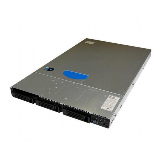
This chapter briefly describes the main features of the server system. This chapter provides illustrations of the product, a list of the server system features, and diagrams showing the location of important components and connections on the server system. TP02157 ® Figure 1. Intel Integrated Server System SR1500AL... -
Page 26: Table 2. Intel ® Server System Sr1500Al Feature Summary
31 pounds (14.1 kg) - max chassis weight ® Server Board Intel Server Board S5000PAL ® ® Processor Support for up to two Dual-Core Intel Xeon processors 5000 sequence • Memory Eight DIMM slots supporting stacked DDR2 533/667 MHz FBDIMM memory •... - Page 27 ® Table 2. Intel Server System SR1500AL Feature Summary Feature Description • Hard Drive Controller Three ESB2 3Gb/s SATA ports (Note: 6 SATA connectors are Options on the server board; only 3 SATA connectors are used in the system) •...
-
Page 28: Chassis Component Identification
M. Control panel (standard control panel shown) Server board Hard drive bays (drives not included) PCI card bracket (full height) Slimline Optical Drive Bay (drive not included) PCI add-in riser assembly Front bezel (optional) Figure 2. ChassisComponents ® Intel Server System SR1500AL User’s Guide... -
Page 29: Figure 3. Server Board Connector And Component Locations
Serial B Configuration Jumper System Fan 4 Header System Fan 3Header ® ® DIMM Sockets Intel 5000P MCH or Intel 5000X Processor 1 Socket Processor 2 Socket Processor Fan 1 Header Voltage Regulator Heat Sink Processor Fan 2 Header Bridge Board Connector... -
Page 30: Configuration Jumpers
If pins 1-2 are jumpered, the BIOS in the lower bank will be selected on the next reset. These pins should be jumpered on 2-3 for normal operation. Figure 4. BIOS Select Jumper ® Intel Server System SR1500AL User’s Guide... -
Page 31: Figure 5. Recovery Jumpers
These pins should be jumpered on 1-2 for normal operation. BMC Force Update Mode If pins 2-3 are jumpered, BMC Force Update Mode is enabled. These pins should be jumpered on 1-2 for normal operation. Figure 5. Recovery Jumpers ® Intel Server System SR1500AL User’s Guide... -
Page 32: Figure 6. Light Guided Diagnostic Leds
® Intel Light Guided Diagnostics The server board contains diagnostic LEDs to help you identify failed and failing components, and to help you identify the server from among several servers. Except for the ID LED, the status LED, and the 5V standby LED, the LEDs turn on (amber) only if a failure occurs. -
Page 33: Figure 7. Back Panel Connectors
No network connection Solid Amber Network connection in place Blinking Amber Transmit/receive activity Right 10 Mbps connection (if left LED is on or blinking) Solid Amber 100 Mbps connection Solid Green 1000 Mbps connection ® Intel Server System SR1500AL User’s Guide... -
Page 34: Figure 8. Active Backplane Components
Front Panel Connector SW RAID Activation Key Fan 1 Power Fan 5 Power Screw Bridge Board Connector Front Panel USB Fan 4 Power M. Backplane Connectors Fan 3 Power Figure 8. Active Backplane Components ® Intel Server System SR1500AL User’s Guide... -
Page 35: Raid Support
The Intel Server System SR1500AL provides an embedded SATA controller that ® supports both 1.5 and 3.0 Gbps data transfer rates. The Intel Server System SR1500ALSAS provides SAS and SATA support. Both systems can be configured for RAID 0, 1, and 10. -
Page 36: Standard Control Panel
Front of Server System Standard Control Panel The diagram below shows the features available on the standard control panel. Another ® option is the Intel Local Control Panel, which is discussed next. TP02160 Callout Feature Function NIC 2 Activity LED Continuous green light indicates a link between the system and the network to which it is connected. -
Page 37: Intel ® Local Control Panel
The front and rear video ports cannot be used at the same time. Figure 10. Standard Control Panel ® Intel Local Control Panel ® The diagram below shows the features available on the Intel Local Control Panel. M L K J TP02099 Callout Feature Function USB 2.0 Port... -
Page 38: Bezels
Two bezels are available. One fits a system that has the ® standard control panel installed. The other is used for a chassis with the other Intel Local Control Panel. Each bezel provides a lock to secure the hard drive and optical drive area. -
Page 39: Rear Of Server System
NIC 1 connector AC Power Receptacle NIC 2 connector Management Network Interface (optional) RJ45 serial B port IO module external connector (optional) M. PS2 keyboard connector USB 1 connector Figure 12. Server System Back ® Intel Server System SR1500AL User’s Guide... -
Page 40: Peripheral Devices
The server system ships with three drive carriers for installing three SAS or Serial ATA (SATA) hot-swap drives. ® Note: SAS drives are supported on the Intel Server System SR1500ALSAS only. One left drive bay can be converted to be used as a floppy bay. To use the bay for a floppy drive, the AXXFLOPHDDTRAY accessory kit must be used. -
Page 41: Slimline Optical Drive Carrier
Server System SR1500AL can be mounted into a rack. Intel provides three options to mount this server into a rack. When installing the chassis into a rack, Intel recommends you install systems from the bottom of the rack to the top. In other words, install the first system in the rack into the bottom position of the rack, the second system in the second position from the bottom, and so on. - Page 42 ® Intel Server System SR1500AL User’s Guide...
-
Page 43: Chapter 3: Hardware Installations And Upgrades
® ® Three Intel rack options are available to install the Intel Server System SR1500AL in a rack. The options are the fixed bracket kit, the basic rail kit, and the tool-less rail kit. Only the tool-less rail kit allows you to service the server system while installed in a rack. The other rack options require the system to be removed from the rack before servicing. -
Page 44: Fixed Bracket Rack Mount Installation
20. Attach the rear end of the outer rail to the rear bracket with at least one screw. If possible, attach at two places. 21. In the same manner, attach the other rail assembly to the other side. ® Intel Server System SR1500AL User’s Guide... -
Page 45: Basic Rail Rack Mount Removal
(attached to the rack). 9. Engage the matching rails and slide the server chassis into the rack until the two safety stops lock into position. 10. Depress the two safety locks (one on each side). ® Intel Server System SR1500AL User’s Guide... -
Page 46: Tool-Less Rail Rack Mount Servicing
Note: Beware of cables when re-installing the system into the rack so that the cables do not get pulled or interfered with. Removing and Installing the Front Bezel ® The front bezels are available as optional accessories for the Intel Server System SR1500AL. Two front bezel options are available. One is used for the standard control ®... -
Page 47: Removing The Front Bezel
Use the steps below if your system includes a front bezel. 1. Unlock the bezel. 2. Disconnect any cables attached to the control panel. 3. Pull the bezel from the server system. TP02199 Figure 16. Removing the Front Bezel ® Intel Server System SR1500AL User’s Guide... -
Page 48: Installing The Front Bezel
Use the steps below if your system includes either the standard front bezel or the front ® bezel for the Intel Local Control Panel. The front bezel is optional. 1. At each end of the bezel, line up the center notch on the bezel with the center guide on the rack handles. -
Page 49: Installing The System Cover
2. Slide the cover forward until it clicks into place (see letter “A”). 3. (Optional) Insert the safety screw at the center of the top cover (see letter “B”) if required. 4. Reconnect all peripheral devices and the AC power cord(s). ® Intel Server System SR1500AL User’s Guide... -
Page 50: Removing And Installing The Processor Air Duct
2. Power down the server and unplug all peripheral devices and the AC power cable. 3. Remove the server system cover. For instructions, see “Removing the System Cover”. 4. Lift the processor air duct from its location over the two processor sockets. ® Intel Server System SR1500AL User’s Guide... -
Page 51: Figure 20. Removing The Processor Air Duct
TP02201 Figure 20. Removing the Processor Air Duct ® Intel Server System SR1500AL User’s Guide... -
Page 52: Installing The Processor Air Duct
7. Install the server system cover. For instructions, see “Installing the System Cover”. 8. Plug all peripheral devices and the AC power cable(s) into the server. ® Intel Server System SR1500AL User’s Guide... -
Page 53: Installing And Removing Memory
2. Turn off all peripheral devices connected to the server. Turn off the server. 3. Disconnect the AC power cord(s) from the server. 4. Remove the system's cover. For instructions, see “Removing the System Cover”. 5. Locate the DIMM sockets (see Figure 23). ® Intel Server System SR1500AL User’s Guide... -
Page 54: Figure 23. Installing The Memory
10. When the DIMM is inserted, push down on the top edge of the DIMM until the retaining clips snap into place (see letter “C” in the figure above). Make sure the clips are firmly in place (see letter “D” in the figure above). ® Intel Server System SR1500AL User’s Guide... -
Page 55: Removing Dimms
1. Observe the safety and ESD precautions in “Safety Information”. 2. Turn off all peripheral devices connected to the server. Turn off the server. 3. Disconnect the AC power cord(s) from the server. ® Intel Server System SR1500AL User’s Guide... -
Page 56: Figure 24. Lifting The Processor Socket Handle
9. Line up the alignment marks on the processor and the socket, and insert the processor into the socket. Note: Make sure the alignment triangle mark and the alignment triangle cutout align correctly. ® Intel Server System SR1500AL User’s Guide... -
Page 57: Installing The Heat Sink(S)
2. Loosely screw in the captive screws on the heat sink corners in a diagonal manner. Do no fully tighten one screw before tightening another. 3. Gradually and equally tighten each captive screw until each is firmly tightened. ® Intel Server System SR1500AL User’s Guide... -
Page 58: Removing A Processor
7. Lift the heat sink from the processor. If it does not pull up easily, twist the heat sink again. Do not force the heat sink from the processor. Doing so could damage the processor. 8. Lift the processor lever. ® Intel Server System SR1500AL User’s Guide... -
Page 59: Removing And Installing The Small Air Baffle
Use these steps only when it is indicated as necessary for a component installation process. Always operate your server system with the small air baffle in place. The small air baffle is required for proper airflow within the server system. ® Intel Server System SR1500AL User’s Guide... -
Page 60: Removing The Small Air Baffle
TP02204 Figure 28. Removing the Small Air Baffle Installing the Small Air Baffle 1. Lower the baffle into the server system. 2. Snap the baffle into place as shown in the figure below. ® Intel Server System SR1500AL User’s Guide... -
Page 61: Installing And Removing A Hot-Swap Hard Drive
2. Open the latch at the front of the hard drive carrier. See letter "A" in the figure below. 3. Pull out on the black lever and slide the carrier from the server system. See letter "B" in the figure below. ® Intel Server System SR1500AL User’s Guide... -
Page 62: Figure 30. Removing Hot-Swap Disk Carrier From The Server System
8. Align the holes in the drive to the holes in the drive carrier and attach it to the carrier with the screws that were attached to the plastic retention device. ® Intel Server System SR1500AL User’s Guide... -
Page 63: Figure 32. Installing Hard Drive Into Carrier
11. Install the server system cover. For instructions, see “Installing the System Cover”. 12. (Optional) Install the front bezel. For instructions, see “Installing the Front Bezel”. 13. Plug all peripheral devices and the AC power cable(s) into the server. ® Intel Server System SR1500AL User’s Guide... -
Page 64: Removing A Sas Or Sata Hot-Swap Hard Disk Drive
AC power cord from the system or wall outlet. To maintain proper system cooling, a filler blank must be installed if you do not install a device at this location. ® Intel Server System SR1500AL User’s Guide... -
Page 65: Installing A Slimline Optical Drive Or Internal Usb Floppy
12. Obtain the cable from the accessory kit and install the cable to the interposer board and the server board. 13. (Optional) For installing the optional USB floppy drive, note the location of the backplane USB connector and refer to the documentation that came with the device. ® Intel Server System SR1500AL User’s Guide... -
Page 66: Removing A Slimline Optical Drive Or Internal Usb Floppy
5. If removing an internal USB floppy drive, unplug it from the backplane. 6. Press the blue release lever (see letter “A”) to unlock the optical drive tray and remove the slimline optical drive tray assembly from the server system as shown in Figure ® Intel Server System SR1500AL User’s Guide... -
Page 67: Figure 36. Removing The Slimline Optical Drive Assembly From The Server System
7. Press downward on the side of the tray (see letter “A”) and disengage the drive from the two metal tabs on the opposite side of the tray. 8. Slide the optical drive out (see letter “B”) to remove it from the tray. ® Intel Server System SR1500AL User’s Guide... -
Page 68: Filling Empty Server System Bays
• If you do not have an optical drive installed in the slimline bay, install the slimline filler panel. • Install empty hard drive carriers into any remaining empty hard drive bays. ® Intel Server System SR1500AL User’s Guide... -
Page 69: Installing And Removing The Pci Riser Assembly
6. Grasp both riser latches with thumb and forefinger (see letter “A”), and pull up to release riser assembly. 7. Lift riser assembly straight up (see letter “B”). AF000358 Figure 38. Removing PCI Riser Assembly from the Server System ® Intel Server System SR1500AL User’s Guide... -
Page 70: Installing The Pci Riser Assembly
7. Install the server system cover. For instructions, see “Installing the System Cover”. 8. (Optional) Install the front bezel. For instructions, see “Installing the Front Bezel”. 9. Plug all peripheral devices and the AC power cable(s) into the server. ® Intel Server System SR1500AL User’s Guide... -
Page 71: Replacing A Pci Riser Card
(see letter “B” in the figure below) and remove from the server system (see letter “C” in the figure below). ® Intel Server System SR1500AL User’s Guide... -
Page 72: Figure 40. Removing The Pci Express* Riser Card From The Server System
14. Re-install the processor air duct. For instructions, see “Installing the Processor Air Duct”. 15. Install the server system cover. For instructions, see “Installing the System Cover”. 16. Plug all peripheral devices and the AC power cable(s) into the server. ® Intel Server System SR1500AL User’s Guide... -
Page 73: Installing The Pci-X* Riser Card
14. Connect any cables to add-in cards that require them. See your add-in card documentation for information and add-in card requirements. 15. Re-install the processor air duct. For instructions, see “Installing the Processor Air Duct”. ® Intel Server System SR1500AL User’s Guide... -
Page 74: Installing And Removing A Pci Add-In Card
8. Insert add-in card until it seats in riser card connector (see letter “C”). AF000361 Figure 42. I Installing a Full Height Add-In Card 9. Close both retention clips. Note: Make sure that all empty add-in card slots have filler panels installed. ® Intel Server System SR1500AL User’s Guide... -
Page 75: Removing A Pci Add-In Card
8. Close both retention clips. Note: Make sure that all empty add-in card slots have filler panels installed. 9. Install the PCI riser assembly into the server system. For instructions, see “Installing the PCI Riser Assembly”. ® Intel Server System SR1500AL User’s Guide... -
Page 76: Installing And Removing The I/O Expansion Module(S)
I/O expansion module(s) to the server board (see letter “C” in the figure below). I/O Module (Dual Gigabit) I/O Module (External SAS) AF000746 Figure 44. Installing the I/O Expansion Module to the Server Board ® Intel Server System SR1500AL User’s Guide... -
Page 77: Removing The I/O Expansion Module(S)
AF000749 Figure 45. Removing the I/O Expansion Module(s) from the Server Board 8. Install the PCI riser assembly into the server system. For instructions, see “Installing the PCI Riser Assembly”. ® Intel Server System SR1500AL User’s Guide... -
Page 78: Rmm Nic
® 7. Insert the standoff into the hole labeled TH4 on the Intel RMM board (see letter ® “D” in the figure below). The standoff installs on the bottom side of the Intel RMM board. ® 8. Attach the Intel RMM board to the server board connector and snap the standoff into the matching hole on the server board. -
Page 79: Removing The Intel ® Rmm And Intel ® Rmm Nic
RMM NIC module cover into the system back panel (see letter “D” in the figure below). AF000900 ® ® Figure 47. Removing the Intel RMM and the Intel RMM NIC Module from the Server System 9. Install the PCI riser assembly into the server system. For instructions, see “Installing the PCI Riser... -
Page 80: Replacing The Backplane Board
(see letter “A” in the figure below), and lifting straight up (see letter “B” in the figure below) AF000373 Figure 48. Removing the Bridge Board from the Server System ® Intel Server System SR1500AL User’s Guide... -
Page 81: Installing The Backplane Board
(see letter “B”). 5. Slide the backplane board to the left (see letter “C”) to lock it in place and tighten the captive screw (see letter “D”). ® Intel Server System SR1500AL User’s Guide... -
Page 82: Figure 50. Installing The Backplane Into The Server System
AF000371 Figure 50. Installing the Backplane into the Server System 6. Connect cables as necessary to the backplane board. ® Intel Server System SR1500AL User’s Guide... -
Page 83: Figure 51. Installing The Bridge Board Into The Server System
Figure 51. Installing the Bridge Board into the Server System 8. Install the server system cover. For instructions, see “Installing the System Cover”. 9. Plug all peripheral devices and the AC power cable(s) into the server. ® Intel Server System SR1500AL User’s Guide... -
Page 84: Installing And Removing The Server Board
6. Place the server board into the server system as shown in the figure below (see letter “A”). 7. Attach the server board with six screws (see letter “B”). AF000379 Figure 52. Installing the Server Board ® Intel Server System SR1500AL User’s Guide... -
Page 85: Removing The Server Board
“Removing the PCI Riser Assembly”. 6. Remove the six screws from the server board (see letter “A”) and lift the server board from the server system (see letter “B”). AF000380 Figure 53. Removing the Server Board ® Intel Server System SR1500AL User’s Guide... -
Page 86: Replacing The Backup Battery
Varning: Explosionsfara vid felaktigt batteribyte. Använd samma batterityp eller en ekvivalent typ som rekommenderas av apparattillverkaren. Kassera använt batteri enligt fabrikantens instruktion. Varoitus: Paristo voi räjähtää, jos se on virheellisesti asennettu. Vaihda paristo ainoastaan laitevalmistajan suosittelemaan tyyppiin. Hävitä käytetty paristo valmistajan ohjeiden mukaisesti. ® Intel Server System SR1500AL User’s Guide... -
Page 87: Figure 54. Replacing The Backup Battery
8. Remove the new lithium battery from its package, and, being careful to observe the correct polarity, insert it in the battery socket. 9. Close the chassis. 10. Run Setup to restore the configuration settings to the RTC. ® Intel Server System SR1500AL User’s Guide... -
Page 88: Replacing The Power Supply
Figure 55. Removing Power Supply Module from the Server System 5. Insert the replacement power supply module into the power supply cage until it clicks into place. AF000367 Figure 56. Installing Power Supply Module into the Server System ® Intel Server System SR1500AL User’s Guide... -
Page 89: Replacing The Control Panel
7. Plug all peripheral devices and the AC power cable(s) into the server. Replacing the Control Panel ® The steps for replacing the standard control panel and the Intel Local Control Panel are nearly identical. Use the steps below for both varieties of the control panel. Where necessary, differences between the two control panels are noted. -
Page 90: Figure 57. Removing The Intel ® Local Control Panel Module
AF000381 ® Figure 57. Removing the Intel Local Control Panel Module 8. Slide the replacement control panel into the server system (see letter “A”) until it clicks into place. 9. Connect the front panel and USB cables to the connectors on the backplane (see letters “B”... -
Page 91: Replacing A System Fan
® The system fans at the front of the Intel Server System SR1500AL can be individually replaced if one of them fails. Use the steps below to replace either a dual rotor fan or a single rotor fan. -
Page 92: Installing And Removing The Rack Handles
4. Align the rack handle with the two holes on the side of the server system as shown in the figure below. 5. Attach the rack handle to the server system with two screws as shown in the figure below. ® Intel Server System SR1500AL User’s Guide... -
Page 93: Removing The Rack Handles
4. Remove the server system cover. For instructions, see “Removing the System Cover”. 5. Remove the two screws holding the rack handle in place, and remove the rack handle from the server system as shown in the figure below. ® Intel Server System SR1500AL User’s Guide... -
Page 94: Figure 62. I Removing The Rack Handle
Figure 62. I Removing the Rack Handle 6. Install the server system cover. For instructions, see “Installing the System Cover”. 7. Plug all peripheral devices and the AC power cable(s) into the server. ® Intel Server System SR1500AL User’s Guide... -
Page 95: Chapter 4: Server Utilities
You can run BIOS Setup with or without an operating system ® being present. See “Server System References” for a link to the Intel 5000 Series Chipsets Server Board Family Datasheet where you will find details about specific BIOS setup screens. -
Page 96: Table 4. Setup Menu Key Use
If "No" is selected and the <Enter> key is pressed, or if the <Esc> key is pressed, the user is returned to where they were before <F9> was pressed without affecting any existing field values. ® Intel Server System SR1500AL User’s Guide... -
Page 97: Upgrading The Bios
Press <F2> Key if you want to run SETUP 2. Write down the current settings in the BIOS Setup program. Note: Do not skip step 2. You will need these settings to configure your server at the end of the procedure. ® Intel Server System SR1500AL User’s Guide... -
Page 98: Upgrading The Bios
2. Open the server chassis. 3. Move the jumper from the normal operation position, Password Clear Protect, at pins 1 and 2 to the Password Clear Erase position, covering pins 2 and 3. ® Intel Server System SR1500AL User’s Guide... -
Page 99: Clearing The Cmos
2. Open the server. 3. Move the jumper from the normal operation position, CMOS Clear by BMC, at pins 1 and 2 to the CMOS Clear Force Erase position, covering pins 2 and 3. ® Intel Server System SR1500AL User’s Guide... -
Page 100: Figure 64. Clear Cmos Jumper
1 and 2. 6. Close the server chassis. 7. Reconnect the AC power and power up the system. 8. The CMOS is now cleared and can be reset by going into the BIOS setup. ® Intel Server System SR1500AL User’s Guide... -
Page 101: Appendix A: Technical Reference
Use caution to make sure no cables or wires are pinched and that the airflow from the fans is not blocked. Use the figures below to determine the correct cable routing. Intel ® Remote Management Module (optional) ®... -
Page 102: Sata Connections
SATA Connections Use the figure below to determine the proper SATA cabling. AF000375 Figure 66. Connecting SATA Cables ® Intel Server System SR1500AL User’s Guide... -
Page 103: 600W Single Power Supply Input Voltages
AF000376 Figure 67. Cabling Around the Small Air Baffle 600W Single Power Supply Input Voltages • 100-127V at 50/60 Hz; 8.55 A max. • 200-240V at 50/60 Hz; 4.3 A max. ® Intel Server System SR1500AL User’s Guide... -
Page 104: 600W Single Power Supply Output Voltages
Warning: Do not exceed a combined power output of 90 Watts for the +5 V and +3.3 V outputs. Exceeding a combined 90 Watts will overload the power subsystem and may cause the power supplies to overheat and malfunction. ® Intel Server System SR1500AL User’s Guide... -
Page 105: System Environmental Specifications
7 Bels in sound power for a typical office ambient temperature (65-75 °F). Your selection of peripherals may change the noise level. Electrostatic Tested to 15 kilovolts (kV); no component damage. discharge (ESD) ® Intel Server System SR1500AL User’s Guide... - Page 106 ® Intel Server System SR1500AL User’s Guide...
-
Page 107: Appendix B: Troubleshooting
In addition to the server firmware and files, also update any drivers used for components you have installed in your system, such as video drivers, network drivers, and SATA drivers. Intel provides a package called the "Platform Confidence Test" that may help with your diagnostics. See “Server System References”... -
Page 108: Problems Following Initial System Installation
• Are all integrated components from the tested components lists? Check the tested memory, and chassis lists, as well as the supported hardware and operating system list. See “Server System References” for links to the tested component lists. ® Intel Server System SR1500AL User’s Guide... -
Page 109: Hardware Diagnostic Testing
Once the system boots up, the operating system prompt appears on the screen. The prompt varies according to the operating system. If the operating system prompt does not appear, “No Characters Appear on Screen”. ® Intel Server System SR1500AL User’s Guide... -
Page 110: Specific Problems And Corrective Actions
Remove the processor(s) and re-seat them. • Make sure the chassis standoffs are installed only below mounting holes. Misplaced standoffs can contact the pins on the bottom of the server board and cause a short. ® Intel Server System SR1500AL User’s Guide... -
Page 111: No Characters Appear On Screen
Characters Are Distorted or Incorrect Check the following: • Are the brightness and contrast controls properly adjusted on the video monitor? See the manufacturer's documentation. • Are the video monitor's signal and power cables properly installed? ® Intel Server System SR1500AL User’s Guide... -
Page 112: System Cooling Fans Do Not Rotate Properly
Light Check the following: • Are the CD-ROM/DVD-ROM drive's power and signal cables properly installed? • Are all relevant switches and jumpers on the drive set correctly? • Is the drive properly configured? ® Intel Server System SR1500AL User’s Guide... -
Page 113: Cannot Connect To A Server
Make sure the other adapter supports shared interrupts. Make sure your operating system supports shared interrupts. • Try reseating the add-in adapter. The add-in adapter stopped working without apparent cause • Reseat the adater. • Put the adapter in a different slot. ® Intel Server System SR1500AL User’s Guide... -
Page 114: System Boots When Installing Pci Card
If you are running the software from a CD-ROM or DVD-ROM, try a different disk. • Check your system for a virus infection. • Uninstall and reinstall the software. Make sure all necessary files are installed. ® Intel Server System SR1500AL User’s Guide... -
Page 115: Devices Are Not Recognized Under Device Manager (Microsoft* Windows* Operating System)
(Microsoft* Windows* Operating System) The Microsoft* Windows* operating systems do not include all of the drivers for the ® Intel chipsets, onboard NICs, and other components. See “Server System References” for a link to the current drivers and chipset files. -
Page 116: Led Information
LED Information ® The Intel Server Board S5000PAL includes LEDs that can aid in troubleshooting your system. A table of these LEDs with a description of their use is listed below. Table 8. LED Information LED Name Function Location LED Color... -
Page 117: Table 10. Error Beep Codes Generated By Intel
® In addition to the beep codes above, additional beep codes are provided if an Intel ® Remote Management Module is installed. The Intel Remote Management Module provides the following additional beep codes. ® Table 10. Error Beep Codes Generated by Intel... - Page 118 ® Intel Server System SR1500AL User’s Guide...
-
Page 119: Appendix C: Intel ® Server Issue Report Form
Appendix C: Intel Server Issue Report Form Note: An on-line / automatic submission version of this form is available at http:// support.intel.com/support/motherboards/server/chassis/SR1500/. For the fastest service, please submit your form via the Internet. Date Submitted: _______________________________________________________ Company Name: ______________________________________________________ Contact Name: ________________________________________________________... -
Page 120: Operating System Information
Revision PCI-X* Top PCI Slot Middle PCI Slot Bottom PCI Slot PCIe* x4 Top PCI Slot Middle PCI Slot Bottom PCI Slot PCIe x8 Top PCI Slot Middle PCI Slot Bottom PCI Slot ® Intel Server System SR1500AL User’s Guide... - Page 121 Drive Type (SCSI, Hot-swap Make/Model SATA, etc) or Fixed Revision Management Information On-Board Platform Instrumentation only ___________________________________ ® Intel Remote Management Module _______________________________________ Control Panel Information Standard Control Panel _________________________________________________ ® Intel Local Control Panel_______________________________________________ ® Intel Server System SR1500AL User’s Guide...
- Page 122 Please also include any details on troubleshooting already done. ____________________________________________________________________ ____________________________________________________________________ ____________________________________________________________________ ____________________________________________________________________ ____________________________________________________________________ ____________________________________________________________________ ____________________________________________________________________ ____________________________________________________________________ ____________________________________________________________________ ____________________________________________________________________ ____________________________________________________________________ ____________________________________________________________________ ____________________________________________________________________ ____________________________________________________________________ ____________________________________________________________________ ____________________________________________________________________ ____________________________________________________________________ ____________________________________________________________________ ____________________________________________________________________ ____________________________________________________________________ ____________________________________________________________________ ® Intel Server System SR1500AL User’s Guide...
-
Page 123: Appendix D: Led Decoder
Appendix D: LED Decoder During the system boot process, BIOS executes a number of platform configuration processes, each of which is assigned a specific hex POST code number. As each configuration routine is started, BIOS will display the given POST code to the POST Code Diagnostic LEDs found on the back edge of the server board. -
Page 124: Figure 68. Diagnostic Led Placement Diagram
Detecting presence of memory 0x24h Programming timing parameters in the memory controller 0x25h Configuring memory parameters in the memory controller 0x26h Optimizing memory controller settings 0x27h Initializing memory, such as ECC init 0x28h Testing memory ® Intel Server System SR1500AL User’s Guide... - Page 125 Resetting the console controller 0x79h Disabling the console controller 0x7Ah Enabling the console controller Keyboard (PS2 or USB) 0x90h Resetting the keyboard 0x91h Disabling the keyboard 0x92h Detecting the presence of the keyboard ® Intel Server System SR1500AL User’s Guide...
- Page 126 Trying boot device selection 0xD4 Trying boot device selection 0xD5 Trying boot device selection 0xD6 Trying boot device selection 0xD7 Trying boot device selection 0xD8 Trying boot device selection 0xD9 Trying boot device selection ® Intel Server System SR1500AL User’s Guide...
- Page 127 Exiting Sleep state 0xF8h Operating system has requested EFI to close boot services (ExitBootServices ( ) has been called) 0xF9h Operating system has switched to virtual address mode (SetVirtualAddressMap ( ) has been called) ® Intel Server System SR1500AL User’s Guide...
- Page 128 Crisis recovery has been initiated because of a user request 0x31h Crisis recovery has been initiated by software (corrupt flash) 0x34h Loading crisis recovery capsule 0x35h Handing off control to the crisis recovery capsule 0x3Fh Unable to complete crisis recovery. ® Intel Server System SR1500AL User’s Guide...
-
Page 129: Appendix E: Getting Help
Telephone All calls are billed per incident, levied in local currency at the applicable credit card exchange rate plus applicable taxes. (Intel reserves the right to change the pricing for telephone support at any time without notice). ® Before calling, fill out an “Intel... -
Page 130: Latin America
Easter Island....Contact AT&T USA at 800 800 311. Once connected, dial 800 843 4481 Mainland and Juan .. Contact AT&T USA at 800 225 288. Once connected, dial 800 843 4481 ® Intel Server System SR1500AL User’s Guide... - Page 131 Panama..Contact AT&T USA at 00 800 001 0109. Once connected, dial 800 843 4481 Paraguay ... 001 916 377 0114 Peru ... 001 916 377 0114 Uruguay..001 916 377 0114 Venezuela... Contact AT&T USA at 0 800 2255 288. Once connected, dial 800 843 4481 ® Intel Server System SR1500AL User’s Guide...
- Page 132 ® Intel Server System SR1500AL User’s Guide...
-
Page 133: Appendix F: Regulatory And Compliance Information
(or higher) and operating at the same (or higher) speed as the microprocessor used on this server board. The final configuration of your end system product may require additional EMC compliance testing. For more information, please contact your local Intel representative. -
Page 134: Product Emc Compliance - Class A Compliance
This server system has been tested and verified to comply with the following electromagnetic compatibility (EMC) regulations when installed in a compatible Intel® host system. For information on compatible host system(s) refer to Intel's Server Builder Web site or contact your local Intel representative. -
Page 135: Certifications / Registrations / Declarations
IRAM Certification (Argentina) • CNCA Certification (China) • Ecology Declaration (International) Product Regulatory Compliance Markings ® This Intel server system product is provided with the following regulatory marks. Table 13. Product Regulatory Compliance Markings Regulatory Compliance Region Marking cULus Listing Marks... - Page 136 Marking C-Tick Mark Australia / New Zealand VCCI Marking (Class A) Japan BSMI Certification Taiwan Number & Class A Warning GOST R Marking Russia RRL MIC Mark Korea China Compulsory China Certification Mark ® Intel Server System SR1500AL User’s Guide...
-
Page 137: Electromagnetic Compatibility Notices
(1) this device may not cause harmful interference, and (2) this device must accept any interference received, including interference that may cause undesired operation. For questions related to the EMC performance of this product, contact: Intel Corporation 5200 N.E. Elam Young Parkway Hillsboro, OR 97124-6497 1-800-628-8686 This equipment has been tested and found to comply with the limits for a Class A digital device, pursuant to Part 15 of the FCC Rules. -
Page 138: Industry Canada (Ices-003)
Install and use the equipment according to the instruction manual. BSMI (Taiwan) The BSMI Certification Marking and EMC warning is located on the outside rear area of the product. ® Intel Server System SR1500AL User’s Guide... -
Page 139: Korean Compliance (Rrl)
Updated product information for configurations can be found on the Intel Server Builder Web site at the following URL: http://channel.intel.com/go/serverbuilder If you do not have access to Intel's Web address, please contact your local Intel representative. •... -
Page 140: Restriction Of Hazardous Substances (Rohs) Compliance
Restriction of Hazardous Substances (RoHS) Compliance Intel has a system in place to restrict the use of banned substances in accordance with the European Directive 2002/95/EC. Compliance is based on declaration that materials banned in the RoHS Directive are either (1) below all applicable substance threshold limits or (2) an approved/pending RoHS exemption applies. -
Page 141: Appendix G: Warranty
"as is" unless specifically provided for otherwise in any software license accompanying the software. If any Product furnished by Intel which is the subject of this Limited Warranty fails during the warranty period for reasons covered by this Limited Warranty, Intel, at its option, will: •... -
Page 142: Warranty Limitations And Exclusions
Limitations of Liability Intel's responsibility under this, or any other warranty, implied or expressed, is limited to repair, replacement, or refund, as set forth above. These remedies are the sole and exclusive remedies for any breach of warranty. -
Page 143: Telephone Support
Telephone Support If you cannot find the information you need on Intel's World Wide Web site (http:// www.intel.com/), call your local distributor or an Intel Customer Support representative. - Page 144 ® Intel Server System SR1500AL User’s Guide...
-
Page 145: Appendix H: Installation/Assembly Safety Instructions
5. Provide some electrostatic discharge (ESD) protection by wearing an antistatic wrist strap attached to chassis ground of the system-any unpainted metal surface-when handling components. 6. Do not operate the system with the chassis covers removed. ® Intel Server System SR1500AL User’s Guide... - Page 146 • Provided with a properly grounded wall outlet. • Provided with sufficient space to access the power supply cord(s), because they serve as the product's main power disconnect. ® Intel Server System SR1500AL User’s Guide...
-
Page 147: Deutsch
Anschlußkabel von den I/O Anschlüssen oder Ports ab. 5. Tragen Sie ein geerdetes Antistatik Gelenkband, um elektrostatische Ladungen (ESD) über blanke Metallstellen bei der Handhabung der Komponenten zu vermeiden. 6. Schalten Sie das System niemals ohne ordnungsgemäß montiertes Gehäuse ein. ® Intel Server System SR1500AL User’s Guide... - Page 148 Schutzhandschuhe tragen. Bei falschem Einsetzen einer neuen Batterie besteht Explosionsgefahr. Die Batterie darf nur durch denselben oder einen entsprechenden, vom Hersteller empfohlenen Batterietyp ersetzt werden. Entsorgen Sie verbrauchte Batterien den Anweisungen des Herstellers entsprechend. ® Intel Server System SR1500AL User’s Guide...
-
Page 149: Français
Notez que le commutateur CC de mise sous tension /hors tension du panneau avant n'éteint pas l'alimentation CA du système. Pour mettre le système hors tension, vous devez débrancher chaque câble d'alimentation de sa prise. ® Intel Server System SR1500AL User’s Guide... - Page 150 Le microprocesseur et le dissipateur de chaleur peuvent être chauds si le système a été sous tension. Faites également attention aux broches aiguës des cartes et aux bords tranchants du capot. Nous vous recommandons l'usage de gants de protection. ® Intel Server System SR1500AL User’s Guide...
-
Page 151: Español
No intente modificar ni usar el cable de alimentación de corriente alterna, si no corresponde exactamente con el tipo requerido. El número de cables suministrados se corresponden con el número de fuentes de alimentación de corriente alterna que tenga el producto ® Intel Server System SR1500AL User’s Guide... - Page 152 4. Inserte el bloqueo de seguridad en el sistema y bloquéelo para impedir que pueda accederse al mismo sin autorización. 5. Conecte todos los cables externos y los cables de alimentación CA al sistema. ® Intel Server System SR1500AL User’s Guide...
-
Page 153: Chinese
"Provisto de una toma de tierra correctamente instalada. • "Provisto de espacio suficiente como para acceder a los cables de alimentación, ya que éstos hacen de medio principal de desconexión del sistema. Chinese ® Intel Server System SR1500AL User’s Guide... -
Page 154: Italiano
1. Aprire e rimuovere il lucchetto dal retro del sistema qualora ve ne fosse uno installato. 2. Togliere e mettere in un posto sicuro tutte le viti delle coperture. 3. Togliere le coperture. ® Intel Server System SR1500AL User’s Guide... - Page 155 • "Dotata di una presa a muro correttamente installata. • "Dotata di spazio sufficiente ad accedere ai cavi di alimentazione, i quali rappresentano il mezzo principale di scollegamento del sistema. ® Intel Server System SR1500AL User’s Guide...
- Page 156 ® Intel Server System SR1500AL User’s Guide...
-
Page 157: Appendix I: Safety Information
To reduce the risk of bodily injury, electrical shock, fire, and equipment damage, read this document and observe all warnings and precautions in ® this guide before installing or maintaining your Intel server product. In the event of a conflict between the information in this document and information provided with the product or on the website for a particular product, the product documentation takes precedence. -
Page 158: Intended Application Uses
Conform to local occupational health and safety requirements when moving and lifting equipment. • Use mechanical assistance or other suitable assistance when moving and lifting equipment. • To reduce the weight for easier handling, remove any easily detachable components. ® Intel Server System SR1500AL User’s Guide... -
Page 159: Power And Electrical Warnings
Do not attempt to modify or use an AC power cord if it is not the exact type required. A separate AC cord is required for each system power supply. ® Some power supplies in Intel servers use Neutral Pole Fusing. To avoid risk of shock use caution when working with power supplies that use Neutral Pole Fusing. -
Page 160: System Access Warnings
To avoid risk of potential electric shock, a proper safety ground must be implemented for the rack and each piece of equipment installed in it. ® Intel Server System SR1500AL User’s Guide... -
Page 161: Electrostatic Discharge (Esd)
Caution: To avoid risk of radiation exposure and/or personal injury: • Do not open the enclosure of any laser peripheral or device • Laser peripherals or devices have are not user serviceable • Return to manufacturer for servicing ® Intel Server System SR1500AL User’s Guide... -
Page 162: Deutsch
Deutsch Sicherheitshinweise für den Server ® ® Das vorliegende Dokument bezieht sich auf Intel Serverplatinen, Intel Servergehäuse (Standfuß und Rack) sowie installierte Peripheriegeräte. Es enthält Warnungen und Vorsichtsmaßnahmen zur Vermeidung von Gefahren durch Verletzung, Stromschlag, Feuer und Beschädigungen von Geräten. Lesen Sie diese Dokument daher sorgfältig, ®... -
Page 163: Zielbenutzer Der Anwendung
Verwenden Sie mechanische oder andere geeignete Hilfsmittel zum Transportieren oder Anheben von Geräten. • Entfernen Sie alle Komponenten, die sich leicht abnehmen lassen, um das Gewicht zu reduzieren und die Handhabung zu erleichtern. ® Intel Server System SR1500AL User’s Guide... -
Page 164: Warnungen Zu Netzspannung Und Elektrizität
Typ entspricht. Jedes Netzteil im System muß über ein eigenes Netzkabel angeschlossen werden. Einige Netzteile von Intel Servern verwenden Nullleitersicherungen. Vorsicht ist geboten im Umgang mit Netzteilen, welche Nullleitersicherungen verwenden, um das Risiko eines elektrischen Schlages zu vermeiden Das Netzteil in diesem Produkt enthält keine Teile, die vom Benutzer gewartet werden... -
Page 165: Warnhinweise Für Den Systemzugang
Gehen Sie bei der Installation von Geräten im Rack immer von unten nach oben vor, und bauen Sie das schwerste Gerät an der untersten Position im Rack ein. Ziehen Sie jeweils immer nur ein Gerät aus dem Rack heraus. ® Intel Server System SR1500AL User’s Guide... -
Page 166: Elektrostatische Entladungen (Esd)
Inbetriebnahme des Systems ohne Abdeckung kann zur Beschädigung von Systemkomponenten führen. So bringen Sie die Abdeckung wieder an: • Vergewissern Sie sich zunächst, daß Sie keine Werkzeuge oder Teile im Gehäuse vergessen haben. ® Intel Server System SR1500AL User’s Guide... -
Page 167: Français
® d’installer ou de mettre à jour votre produit serveur Intel En cas de conflit entre les informations fournies dans ce document et celles livrées avec le produit ou publiées sur le site Web pour un produit particulier, la documentation du produit prime. -
Page 168: Domaines D'utilisation Prévus
Bien ventilé et à l’écart des sources de chaleur telles que la lumière directe du soleil et les radiateurs. • À l’écart des sources de vibration ou des chocs physiques. • Isolé des champs électromagnétiques importants produits par des appareils électriques. ® Intel Server System SR1500AL User’s Guide... -
Page 169: Pratiques De Manipulation De L'équipement
Vous devez les débrancher avant d’ouvrir le châssis, d’ajouter ou de supprimer un composant non connectable à chaud. Les alimentations de certains serveurs Intel sont munies de doubles fusibles pôle/neutre: veuillez observer les précautions d'usage afin d'éviter tout risque d'eléctrocution. -
Page 170: Avertissements Sur Le Cordon D'alimentation
Éteignez le système en appuyant sur le bouton d’alimentation. • Déconnectez l’alimentation secteur en débranchant tous les cordons d’alimentation secteur du système ou de la prise murale. • Déconnectez l’ensemble des câbles et lignes de télécommunication qui sont connectés au système. ® Intel Server System SR1500AL User’s Guide... -
Page 171: Avertissements Sur Le Montage En Rack
étiqueté comme contrôlant toute l’unité, et pas uniquement le ou les serveurs. Pour éviter tout risque d’électrocution, le rack et chaque élément de l’équipement installé dans le rack doivent être correctement reliés à la terre. ® Intel Server System SR1500AL User’s Guide... -
Page 172: Décharges Électrostatiques (Esd)
Vérifiez tout d’abord que vous n’avez pas oublié d’outils ou de composants détachés à l’intérieur du système. • Vérifiez que les câbles, les cartes d’extension et les autres composants sont correctement installés. • Fixez les panneaux au châssis en suivant les instructions du produit. ® Intel Server System SR1500AL User’s Guide... -
Page 173: Périphériques Laser
Español Información de seguridad del servidor Este documento se aplica a las tarjetas de servidor de Intel®, las carcasas de servidor de Intel® (montaje en bastidor y en pedestal) y los dispositivos periféricos. Para reducir el riesgo de daños corporales, descargas eléctricas, fuego y en el equipo, lea este documento y preste atención a todos las advertencias y precauciones de esta guía antes de instalar o... -
Page 174: Aplicaciones Y Usos Previstos
Provista de una toma de corriente alterna correctamente conectada a tierra. • Provista de espacio suficiente para acceder a los cables de la fuente de alimentación ya que constituyen la desconexión principal de la alimentación. ® Intel Server System SR1500AL User’s Guide... -
Page 175: Manipulacién Del Equipo
CA estén desenchufado antes de abrir la carcasa, agregar o extraer cualquier componente que no es de conexión en funcionamiento. Algunas fuentes de alimentación de electricidad de los servidores de Intel utilizan el polo neutral del fuselaje. Para evitar riesgos de choques electricos use precauciónes al trabajar con las fuentes de alimentación que utilizan el polo neutral de fuselaje. -
Page 176: Advertencias El Acceso Al Sistema
Devuélvala al fabricante para repararla. • Apague el servidor y desconecte todos los cables de alimentación antes de agregar o reemplazar cualquier componente que no es de conexión en funcionamiento. ® Intel Server System SR1500AL User’s Guide... -
Page 177: Advertencias Sobre El Montaje En Bastidor
Precaución: Las descargas electrostáticas pueden dañar las unidades de disco, las tarjetas y otros componentes. Recomendamos que realice todos los procedimientos en una estación de trabajo protegida contra descargas electrostáticas. En caso de que no haya una ® Intel Server System SR1500AL User’s Guide... -
Page 178: Otros Riesgos
Compruebe primero que no ha dejado herramientas o piezas sueltas dentro del sistema. • Compruebe que los cables, tarjetas adicionales y otros componentes están instalados correctamente. • Sujete las cubiertas a la carcasa siguiendo las instrucciones del producto. ® Intel Server System SR1500AL User’s Guide... - Page 179 Precaución Para evitar el riesgo de la exposición a radiaciones o de daños personales: • No abra la caja de ningún periférico o dispositivo láser • Los periféricos o dispositivos láser no pueden ser reparados por el usuario • Haga que el fabricante los repare ® Intel Server System SR1500AL User’s Guide...
- Page 180 ® Intel Server System SR1500AL User’s Guide...
Need help?
Do you have a question about the SR1500AL - Server System - 0 MB RAM and is the answer not in the manual?
Questions and answers