Table of Contents
Advertisement
Quick Links
Advertisement
Chapters
Table of Contents
Troubleshooting

Subscribe to Our Youtube Channel
Related Manuals for Omron 2D CODE READER


Summary of Contents for Omron 2D CODE READER
- Page 1 Cat. No. Z242-E1-03 V400-F050/250/350 2D Code Reader USER’S MANUAL...
- Page 2 Application Considerations (Read and understand this information first.) Studying the V400-F Section 1 Changing Reading Conditions Section 2 Setting RS-232C and Discrete I/O Communication Conditions Section 3 Other Settings Section 4 Communicating with PC and Programmable Controller Section 5 Troubleshooting...
- Page 3 The following are some examples of applications for which particular attention must be given. This is not intended to be an exhaustive list of all possible uses of the products, nor is it intended to imply that the uses listed may be suitable for the products: •...
- Page 4 FOR THE INTENDED USE WITHIN THE OVERALL EQUIPMENT OR SYSTEM. PERFORMANCE DATA Performance data given in this document is provided as a guide for the user in determining suitability and does not constitute a warranty. It may represent the result of OMRON’s test conditions, and the users must correlate it to actual application requirements.
-
Page 5: Introduction
Introduction Meanings of Signal Words In this manual, precautions are indicated using the following symbols and signal words to ensure safe V400-F050/250/350. The precautions indicated by these symbols and signal words use of the are important for safety and must be observed. -
Page 6: Regulations And Standards
• Do not use the product in environments with flammable or explosive gases. • Do not install outdoors. • Do not install the product close to high-voltage devices and power devices in order to secure the safety of operation and maintenance. -
Page 7: Precautions For Correct Use
• Locations subject to oil or chemical spray Ambient Temperature • Maintain a minimum clearance of 50 mm above and below the product to improve air circulation. • Do not install the product immediately above significant heat sources, such as heaters, transformers, or large-capacity resistors. - Page 8 • Do not connect or disconnect the cables while power is supplied. • Do not connect a cable to the 2D Code Reader if the other end of the cable is connected to a personal computer or a Programmable Controller.
-
Page 9: How To Use This Manual
Auto* The code type will be identified automatically. Shape Select the code shape. This item is effective only when [DataMatrix] is selected for [Code Type]. Square The code will be read as a square code. Rectangle The code will be read as a rectangular code. -
Page 10: Visual Aids
Introduction Visual Aids Indicates points that are important in using product functions or in application procedures. Indicates page numbers providing related information. Indicates helpful information when a problem occurs and explanations of technical terms. V400-F050/250/350 User’s Manual... -
Page 11: Table Of Contents
Setting Reading Conditions Manually Selecting the Bank to be Used Normally Copying a Bank Deleting the Content of a Bank Setting the Retry Method Section 3 Setting RS-232C and Discrete I/O Communication Conditions Setting RS-232C Communication Conditions V400-F050/250/350 User’s Manual... - Page 12 Section 4 Other Settings Setting Screen Display Viewing the Images Read in the Past Saving/Initializing All the Settings Displaying the Version Information Section 5 Communicating with PC and Programmable Controller RS-232C Communication Discrete I/O Communication Section 6 Troubleshooting Error Codes and Corrective Actions...
- Page 13 Introduction MEMO V400-F050/250/350 User’s Manual...
-
Page 14: Section 1 Studying The
Section 1 Studying the V400-F This section provides items, such as the V400-F is features, installation, connections and operation flow, with which the operator should be familiar to use the V400-F. Features and Functions of V400-F Compact and Easy-to-Operate Advanced Functions... -
Page 15: Features And Functions Of V400-F
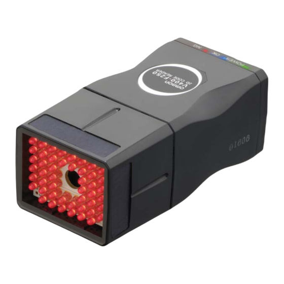
Studying the V400-F Features and Functions of V400-F This fixed type 2D code reader provides advanced reading functions and is designed for easy operation by anyone. It reads 2D codes directly marked on boards and metal materials. Two types of code reader are available: the V400-F250/350, whose lens and light are integrated into one compact body, and the V400-F050, to which a C-mount lens can be attached to enable use of various lights. - Page 16 Reading can be started without monitor. Programmable controller Various Retry Functions p.41) Retry can be performed not only with different exposure time, but also with Power two or more reading conditions that supply are switched automatically.
-
Page 17: Advanced Functions
Two condition switching methods are available: one which determines the order of the conditions to be used automatically according to the frequency of their use, and the other that switches them according to the registered order. Combining with the retry settings that are made for each reading condition enables various retry settings. -
Page 18: Other Features
Saves up to 28 past read images p.53) This allows you to identify the errors that occurred, by checking the saved past images. Supports NPN/PNP by simply exchanging the cable. Allows direct power supply to the monitor. Use of the monitor cable (V400-WM0) and LCD monitor (F150-M05L-2D) enables the V400-F to supply power to the monitor, making settings monitoring and maintenance easy. -
Page 19: Installing And Connecting The Code Reader
There are two mounting methods: “DIN track mounting” and “Base mounting”. Field of Vision and Distance from the Code • An accurate image will not be obtained if the installation distance is too long or too short. Always use the installation distance given below. - Page 20 2-M3 (Screw fitting length: 5 mm or less) Mounting the Mount Seat First mount the mount seat, then mount the reader to the seat with two M4 screws. The reader can also be mounted with one 1/4-20UNC screw. Mounting dimensions...
-
Page 21: Connecting Peripheral Devices
Peripheral devices may be damaged if the cable is connected or disconnected with the power ON. The connector (CN2) for the monitor is capped when the reader is shipped. The cap must be left on those connectors that are not used to protect them from dust, dirt and static electricity. - Page 22 Use a DC power supply with safety measures against high-voltage spikes (safety extra low- voltage circuits on the secondary side). If UL recognition is required for the overall system, use a UL Class II DC power supply.
-
Page 23: Simple Teaching
Section 1 Studying the V400-F Simple Teaching Use “Simple Teaching” to check whether codes on the work piece are readable. “Simple Teaching” enables you to set necessary reading conditions automatically by simple operations. To change reading conditions or set them in detail, use the setting mode. - Page 24 Studying the V400-F • The teaching results will be overwritten, registered to [Bank #00], and saved. • If [Cancel] is selected in the result display screen, the results will not be saved. Exiting Turn OFF the power to the power supply device and then to the monitor.
-
Page 25: Changing Settings
Section 1 Studying the V400-F Changing Settings The setting mode allows you to make changes to reading conditions and system settings. This section explains operations for the setting mode. Switch to the setting mode. Hold down the center button for more than two seconds. - Page 26 Select [Bank Setting] from [Setting Menu]. • Up to 10 reading conditions are available. • When a reading condition is selected, its settings will be displayed in the right area of the screen. • Select the desired reading condition from among the ten conditions, and set each condition item manually or by teaching.
-
Page 27: Reading Results
Reading was not completed within the specified period of time. Check the work piece and lighting condition, then perform teaching again. Increase the reading timeout value. If reading has failed, it may be possible that the cause can be identified by checking the read image. p.53 Highlighting Display The screen is enclosed in a frame whose color that indicates the reading status. - Page 28 “1” will be displayed if the code is contrast is the minimum readable level. Focus Evaluates the focus level of the image. If the code is out of focus, it can no longer be recognized. The more the code is out of focus, the smaller the value displayed. Cell Evaluates the number of recognition fails for each cell in the finder pattern, timing pattern and data.
-
Page 29: Rs-232C Communications Output
Number of read data digits Code quality Read data “Number of read data digits” and “Code quality” are output only if [Digit Data] and [Checker Data] are set to [ON] in the data format setting. p.46 When reading has failed By factory default, an error code is output in the following format. -
Page 30: Section 2 Changing Reading Conditions
Section 2 Changing Reading Conditions This section provides information required for changing reading conditions. Setting Reading Conditions by Teaching Setting Reading Conditions Manually Selecting the Bank to be Used Normally Copying a Bank Deleting the Content of a Bank Setting the Retry Method... -
Page 31: Setting Reading Conditions By Teaching
Section 2 Changing Reading Conditions Setting Reading Conditions by Teaching Teaching uses one sample to read it and sets a reading condition based on the results. Switch to the setting mode. STILL/LIVE MODE TRIG Hold down the center button for more than two seconds to EXECUTE DOWN activate the setting mode. - Page 32 The brightness is adjusted based on the exposure EXECUTE DOWN time. The longer the exposure time, the brighter Press the image but the image is easily blurred if the work piece is not stationary. p.91 Confirm the brightness. STILL/LIVE MODE TRIG Press the center button.
-
Page 33: Setting Reading Conditions Manually
This section explains how to set reading conditions manually. Switch to the setting mode. STILL/LIVE MODE TRIG Hold down the center button for more than two seconds to EXECUTE DOWN activate the setting mode. Hold down for more “Changing Settings” p.24 than two seconds. - Page 34 [Search Region] Set the image region to be read. The region enclosed by the red and green boundary lines will be the subject of reading. The region boundary lines move in Start Y real time as you change the setting.
- Page 35 Changing Reading Conditions [Filter] Set the image processing to be performed at completion of reading. This will lower the possibility of reading failure. Filtering can be performed in 3 steps (filter type can be selected from Smooth, Dilate, Erosion and Median).
- Page 36 Select the number of cells present for each side of the code. The size varies with the code. 10 × 10 to 64 × 64 This item can be selected only when [Square] is selected for [Shape]. 8 × 18 to 16 × 48 This item can be selected only when [Rectangle] is selected for [Shape].
- Page 37 Set the number of times (Times) capture is to be repeated. This item can be selected only when [Normal] is selected for [Retry]. The default settings are indicated with an asterisk (*). However, in the case of [Bank #00], [Exposure] will be set for [Retry] as the default. V400-F050/250/350...
-
Page 38: Selecting The Bank To Be Used Normally
If you select [Cancel], the operation menu will reappear without reflecting the changes. An asterisk (*) will appear at both right and left ends of the reading condition to be normally used. Save the settings. Select [Save] from [Setting Menu] to save the changes you have made to the reading condition. -
Page 39: Copying A Bank
Section 2 Changing Reading Conditions Copying a Bank This section explains how to copy the content of one bank to another bank. Switch to the setting mode. STILL/LIVE MODE TRIG Hold down the center button for more than two seconds to EXECUTE DOWN activate the setting mode. - Page 40 Section 2 Changing Reading Conditions A confirmation message will be displayed. Execute copy. Select [OK] to execute copy. This will bring you to the operation menu. If you select [Cancel], the previous menu will reappear without reflecting the changes. Save the settings.
-
Page 41: Deleting The Content Of A Bank
If you select [Cancel], the operation menu will reappear without deletion. The content of the selected bank will be deleted, and the default settings will be restored for that bank. Save the settings. Select [Save] from [Setting Menu] to save the settings. -
Page 42: Setting The Retry Method
Section 2 Changing Reading Conditions Setting the Retry Method This section explains how to set the retry method (to execute reading and then capture an image twice or more). Two retry methods are available: “Same bank” and “Bank Switching”. Item... - Page 43 #00 to #09, None* 5th Bank Total Timeout 1000 to 9999 (9999*) Set the time at which reading is to be stopped following start of bank switch retry in case of reading failure. Switch Order Select the reading condition switching method.
-
Page 44: Section 3 Setting Rs-232C And Discrete I/O Communication Conditions
Section 3 Setting RS-232C and Discrete I/O Communication Conditions This section explains how to set RS-232C and discrete I/O communication conditions. Setting RS-232C Communication Conditions Setting Communication Conditions Setting the Data Format Setting Discrete I/O Communication Conditions V400-F050/250/350 User’s Manual... -
Page 45: Setting Rs-232C Communication Conditions
Section 3 Setting RS-232C and Discrete I/O Communication Conditions Setting RS-232C Communication Conditions This section explains how to set RS-232C communication conditions and data format. Setting Communication Conditions Set RS-232C communication conditions as follows. Switch to the setting mode. STILL/LIVE MODE... - Page 46 The stop bit indicates the end of data. The default settings are indicated with an asterisk (*). Make the communication settings as follows when using save or load command (e.g. CB, CU). Parity: None, Data Length: 8, Stop Bit: 1 p.71...
-
Page 47: Setting The Data Format
Setting the Data Format Set the RS-232Cdata format as follows. Switch to the setting mode. STILL/LIVE MODE TRIG Hold down the center button for more than two seconds to EXECUTE DOWN activate the setting mode. Hold down for more “Changing Settings” p.24 than two seconds. - Page 48 Select whether to add a value that indicates the code quality when the data is output. Digit Data Select whether to add a value that indicates the number of read data digits when the data is output. OFF* No value will be added.
-
Page 49: Setting Discrete I/O Communication Conditions
Section 3 Setting RS-232C and Discrete I/O Communication Conditions Setting Discrete I/O Communication Conditions This section explains the procedure of setting the input/output of discrete I/O. Switch to the setting mode. STILL/LIVE MODE TRIG Hold down the center button for more than two seconds to EXECUTE DOWN activate the setting mode. - Page 50 Reading is performed continuously while the trigger signal is Trigger Error Select whether to output a discrete I/O error when a trigger is received during BUSY. A discrete I/O error will be output when a trigger is received during BUSY.
- Page 51 Section 3 Setting RS-232C and Discrete I/O Communication Conditions MEMO V400-F050/250/350 User’s Manual...
-
Page 52: Section 4 Other Settings
Section 4 Other Settings This section explains how to set screen display, operate images read in the past, save and initialize settings of the V400-F. Setting Screen Display Viewing the Images Read in the Past Viewing Stored Images Selecting the Images to be Stored... -
Page 53: Setting Screen Display
COM Monitor This screen displays the RS-232C communication history. Emphasis Highlights the reading state. Image State Select how the standby state is to be displayed at completion of start-up. STILL* Displays a still image. LIVE Displays a real-time image. The default settings are indicated with an asterisk (*). -
Page 54: Viewing The Images Read In The Past
This will help you analyze the causes of reading failures. Up to 28 images can be stored in the reader. If more than 28 images are taken, the stored images will be replaced with new ones, starting from the oldest image. These images will be deleted when the power is turned OFF. - Page 55 [Refer to Image] screen. The [Image Store] menu will be displayed. Select [Cancel] to close the [Image Store] menu. If the current setting for [Store Mode] is satisfactory, select [OK] to close the menu. The [System Setting] menu will be displayed. V400-F050/250/350...
-
Page 56: Selecting The Images To Be Stored
EXECUTE DOWN activate the setting mode. Hold down for more “Changing Settings” p.24 than two seconds. Select [System Setting] → [Image Store] → [Store Mode] from [Setting Menu]. Select the images to be stored. Setting item Settings Details Store Mode NG only* Only the reading-failed images will be stored. -
Page 57: Saving/Initializing All The Settings
Saving All the Settings Save all the settings including reading conditions and system settings to the internal ROM as follows. Once they are saved to the internal ROM, they will not be deleted even if the power is turned OFF. -
Page 58: Initializing All The Settings
Hold down for more “Changing Settings” p.24 than two seconds. Select [Initialize] from [Setting Menu]. A confirmation menu will appear. [Select [OK]. All the settings will be initialized to the factory settings, and the [Setting Menu] will reappear. V400-F050/250/350 User’s Manual... -
Page 59: Displaying The Version Information
Displaying the Version Information Display the software version as follows. Switch to the setting mode. STILL/LIVE MODE TRIG Hold down the center button for more than two seconds to EXECUTE DOWN activate the setting mode. Hold down for more “Changing Settings” p.24 than two seconds. -
Page 60: Section 5 Communicating With Pc And Programmable Controller
Section 5 Communicating with PC and Programmable Controller This section explains the commands required to make a connection and communicate with a PC or programmable controller via RS-232C or discrete I/O. RS-232C Communication Wiring Diagram List of Commands Discrete I/O Communication... -
Page 61: Rs-232C Communication
Communicating with PC and Programmable Controller RS-232C Communication It is possible to input a reading trigger and output reading results via RS-232C. This section explains connecting method and commands. For the setting method of communication mode and conditions, refer to “Setting Communication Conditions”... - Page 62 Communicating with PC and Programmable Controller Programmable Controller A D-SUB 9-pin connector (male) is used for the cable type V400-W23 (NPN type) and V400-W23P (PNP type). The connector is compatible with the connection port on OMRON CJ-series and CS-series Programmable Controller.
- Page 63 Performs teaching without changing the exposure time. p.70 Checks the software version. p.71 Commands that Save and Load Data Use the following commands to back up the settings you made to the code reader or Command Function Page Backs up the setting data to the PC.
- Page 64 Number of read data digits Code quality Read data • In the explanation of the format for each command, only “content of reply” when a command is executed correctly is given. • The content of reply when a command is not executed will be...
- Page 65 Communicating with PC and Programmable Controller Data Format for Each Command Function... Performs one reading. Reading is executed with the retry condition that is set when a trigger is input. “Number of read data digits” and “Code quality” are output only if they are set.
- Page 66 Section 5 Communicating with PC and Programmable Controller Function... Performs continuous reading. “Number of read data digits” and “code quality” are output only if they are set. p.47 Input • When reading is successful Output Read data • When reading has failed N G Error Code Data is output each time reading is executed.
- Page 67 Section 5 Communicating with PC and Programmable Controller Function 1... Checks the monitor image display mode (still image/real-time image). Input Output Image display state Image display Details state Switches to still image. Switches to real-time image. Function 2... Switches the monitor image display mode (still image/real-time image).
- Page 68 Only the mode is switched (no trigger is input). Input Trigger mode Set the desired trigger mode as shown below. Trigger mode Details One-shot trigger Continuous trigger Level trigger Output If the level trigger is selected, error code for reading failure will not be output. V400-F050/250/350 User’s Manual...
- Page 69 Function 1... Checks the currently used reading condition No. (Bank #00 to #09). Input Output Reading condition No. Function 2... Switches the reading condition No. (Bank #00 to #09) to be used. Input Reading condition No. Set a reading condition No. (0 to 9).
- Page 70 The light connected to the right The light is OFF. connector (R) is ON. The light is OFF. The light is OFF. Function 2... Switches the light to be turned ON from one to another. Input Light Specify the light to be turned ON. Details...
- Page 71 To automatically set the exposure time, enter "LT AUTO". Output The value specified with the LT command causes a difference of max. 0.04 msec. However, it will not affect the reading process. Function... Performs teaching without changing the exposure time.
- Page 72 B0 to 9 Corresponding reading condition data 00 to 27 Corresponding image No. Output After “READY” is output, the main unit switches to XMODEM communication automatically, and outputs when communication is completed successfully. Function... Loads the setting data from the PC.
- Page 73 Section 5 Communicating with PC and Programmable Controller Function... Saves the reading conditions and system settings to the flash memory of the reader. Input Output V400-F050/250/350 User’s Manual...
-
Page 74: Discrete I/O Communication
Communicating with PC and Programmable Controller Discrete I/O Communication It is possible to execute reading from the programmable controller and output reading result (OK/NG) via discrete I/O. For the setting method of communication mode and conditions necessary to communicate via discrete I/O, refer to “Setting Discrete I/O Communication Conditions”... - Page 75 (TRIG, RESET) *1: ON current/ON voltage This refers to the current or voltage values needed to shift from the OFF →ON state. The ON voltage value is the following potential difference. • NPN type: Potential difference between 24 V terminal and input terminal •...
- Page 76 Inputs a reading trigger from a photoelectric sensor etc. Make sure that the TRIG is ON for at least 0.5 ms. The interval at which the TRIG can be input depends on the reading time. The BUSY signal is output during reading process to disable input of the TRIG.
- Page 77 Selected for [OK/NG Output] The OK/NG signal is not output when reading has failed. • If [NG Pulse] is selected for [OK/NG Output], the OK/NG signal will not be output when reading is successful. • If [OFF] is selected for [NG Output], no outputs will be made via RS-232C when reading has failed.
- Page 78 The OK and NG signals are expressed as level signals. The signals are input when the BUSY signal switches from ON to OFF. If [OFF] is selected for [NG Output], no outputs will be made via RS-232C when reading has failed. Power ON...
- Page 79 If the TRIG signal is turned OFF before reading is successful, reading failure will result. Even if an item other than [NG Pulse] is selected for [OK/NG Output], this signal will perform the same operation as when [One Shot] is selected.
- Page 80 Reading and result output are repeated while the TRIG signal is ON. The BUSY signal will remain ON while reading is executed repeatedly. With this setting, correct detection is not possible if [Level] is selected for [OK/NG Output]. Set [OK Pulse] or [NG Pulse] for [OK/NG Output].
- Page 81 Section 5 Communicating with PC and Programmable Controller MEMO V400-F050/250/350 User’s Manual...
-
Page 82: Section 6 Troubleshooting
Section 6 Troubleshooting This section explains the countermeasures to take when reading cannot be executed correctly or when a problem occurs. Error Codes and Corrective Actions Troubleshooting Connection Errors Reading Errors Discrete I/O Errors RS-232C Errors V400-F050/250/350 User’s Manual... -
Page 83: Error Codes And Corrective Actions
Section 6 Troubleshooting Error Codes and Corrective Actions This section lists the error codes that may be displayed on the screen when reading fails, along with their corrective actions. They are given in error code order. Error Code Action ?E000 2D code cannot be found, possibly due to uneven background. - Page 84 Page Cannot communicate. • Is the cable connected correctly? p.20 p.44 • Do the communication specifications match those of the host device? p.45 • Is the correct communication mode selected? Communication status is • Switch to the communication display. p.52 unknown.
- Page 85 Section 6 Troubleshooting MEMO V400-F050/250/350 User’s Manual...
-
Page 86: Appendix
Line Speed and Reading Time/Exposure Time Exposure Time Reading Time Maintenance Handling the Code Reader Inspection Specifications and Dimensions ASCII Table Ladder Programming Example for Connecting to a PLC 100 FCS Check Program Example (BASIC) Data Capacity Table Menu Hierarchy V400-F050/250/350 User’s Manual... -
Page 87: Lens And Lighting
Appendix Lens and Lighting Please note that the field of vision and installation distance differ between V400-F250 and V400-F350. When choosing a lens and light for V400-F050, refer to the explanation given below. Light and Lens V400-F050 If V400-F250/350 do not meet the requirements of field of vision and installation distance, use V400-F050, which is a C-mount type and allows connection of an external light. - Page 88 Outer ring Emitting color diameter diameter angle MLRL-CR48 Ø48 Ø74 30° Coaxial light A stable image can be obtained with few shadows from uneven surfaces on workpieces. Model Emitting Box height Light path color (mm) extension distance (mm) MSCL-CR24 MSCL-CG24...
- Page 89 Setting the Field of Vision and Working Distance Refer to the following formula to calculate the field of vision and working distance. (Code size: C) + 2 × (Cell size: S) < (Field of vision: A) < 121 × (Cell size: S) Number of effective 640 (H) ×...
- Page 90 Model ML-3519 ML-5018 ML-7527 ML-10035 External dimensions Lock With focus/diaphragm lock mechanism mechanism Mount C-mount Extension tube Model Configuration ML-EXR Thickness: 7 rings/set (0.5 mm, 1 mm, 2 mm, 5 mm, 10 mm, 20 mm, 40 mm) V400-F050/250/350 User’s Manual...
- Page 91 614.0 400.1 Source: Lenses, lighting, and peripheral devices for image processing catalog from Moritex Note: Since values shown in the table are calculated values they may differ from actual measured values. They must be used as your reference. V400-F050/250/350 User’s Manual...
-
Page 92: Line Speed And Reading Time/Exposure Time
*2: The moving shift tolerance is 10% of the cell size. Example: When V = 60 mm/s, C = 1.6 mm, M = 16, A = 10 mm, N = 512, R = 300 ms and L = 30 mm The exposure time is calculated as follows, which will not cause problems with reading. -
Page 93: Reading Time
(Reading time: R) (Max. line speed: V) If the reading time does not meet this formula, the code will be outside the field of vision so the code cannot be read even if the requirement of exposure time is satisfied. -
Page 94: Maintenance
If they get dirty or scratched, image pickup will deteriorate, disabling code reading. •Do not touch the lens and light cover surface with your fingers or any pointed object. •The code reader must be used in a dust-free environment. -
Page 95: Specifications And Dimensions
Appendix Specifications and Dimensions Main unit V400-F050 (Unit: mm) Light connector Power/ (84.1) (R-CH) Monitor cable communication 75.3 connector connector Ø11.5 Ø11.5 Light connector (L-CH) 4-M3 1"-32UN-2A 26.8 25.4 Depth 5 (C-mount) (16.8) V400-F250/350 (Unit: mm) Power/ (105.9) communication Monitor cable connector 97.1... - Page 96 Burst continuation time: 15 ms; Period: 300 ms Applicable standards CE...EN61326: 1997,+A1: 1998+A2: 2001 (EMI: Class A) Vibration resistance 10 to 150 Hz at a single-amplitude of 0.35 mm (maximum acceleration: 50 m2/s), 10 times for 8 minutes each in 3 directions Shock resistance 150 m/ ;...
- Page 97 (Unit: mm) L (Note 1) 39.8 12-pin round connector D-sub 9-pin connector Vinyl insulated round cord Ø6.8, 12 cores Nameplate Note 1: The cable length (L1) must be as follows. Length L General specifications Model V400-W23/P V400-W24/P I/F connector D-sub 9-pin connector (male)
- Page 98 (See note 2.) Vinyl insulated round cord Ø6.5, 3 cores Nameplate Note 1: The cable length (L1) must be as follows. Length L Note 2: These two wires are for a 24-V output. Do not use them for input; doing so may result in malfunction.
- Page 99 20.4 to 26.4 VDC Current consumption 700 mA max. Vibration resistance 10 to 150 Hz at a single-amplitude of 0.1 mm (maximum acceleration: 15 m/s 10 times for 8 minutes each in 3 directions Shock resistance 150m/s ; 3 times each in 6 directions Ambient temperature Operating: 0 to +50°C;...
-
Page 100: Ascii Table
Appendix ASCII Table Data read using RS-232C is output as 2 ASCII characters. The ASCII characters correspond to the following characters. (Examples) •When the read data is A, 41 is output. •When the data read is T, 54 is output. -
Page 101: Ladder Programming Example For Connecting To A Plc
Appendix Ladder Programming Example for Connecting to a PLC Connections Used in this Example The following configuration is used in this example. Cable 2D code reader V400-W23 (NPN type) V400-F050/250/350 V400-W23P (PNP type) POWER STILL/LIVE MODE TRIG EXECUTE DOWN Programmable controller... - Page 102 Appendix CS/CJ-series PLC Settings Change the settings in the PLC Setup to those shown below using the CX-Programmer and then transfer the settings to the CPU Unit of the PLC. Communications Settings: Select the Custom Option and then set the baud rate to 9,600 and the format to “8,1,N”.
- Page 103 Appendix Sample Programming for CJ-series PLC Using a Software Trigger With the following programming, the V400-F will start reading when the Read Start Bit (CIO 0.00) turns ON. The reading results will be stored in DM200 to DM220. A200.11 MOV(021)
- Page 104 Appendix Sample Programming for CJ-series PLC Using a Hardware Trigger With the following programming, the results of reading using a hardware trigger will be stored in DM200 to DM220. A392.06 @BSET(071) Reception Clears the data from DM200 to Completed #0000 DM220.
-
Page 105: Fcs Check Program Example (Basic)
Sample data string Data length CODE$ Data character Exclusive OR '* * * * * CALCULATE FCS * * * * * '* FCSSET L = LEN (DATA$) A = 0 FOR J = 1 TO L CODE$ = MID$ (DATA$,J,1) - Page 106 The FCS can be attached to output data to improve the reliability of communications. Each time data is received, the PC calculates the FCS and checks it against the FCS attached to the sent data so that the send data can be checked for errors.
-
Page 107: Data Capacity Table
Appendix Data Capacity Table The maximum quantity of information that can be stored depends on the symbol size of the code. Also the maximum data capacity in relation to the amount of information carried by the code depends on the character type and the arrangement and combination of characters. The relation between the symbol size (number of cells) and data capacity is shown in the following table. - Page 108 Appendix QRCode QRCode (Model 2) In the following diagram, the symbol size is 21 × 21 (Version 1). 7 cells 7 cells 7 cells 7 cells 14 cells Data capacity Symbol size Error correction level Numeral Alphanumeric 8-bit byte Japanese...
- Page 109 Source: 2D Codes, Basic Specifications for QR Code (JIS X 0510) Maximum Data Capacity Even with the same 2D code, the maximum quantity of information that can be stored depends on the symbol size of the code. In other words, the symbol size must be increased to increase the data capacity.
-
Page 110: Menu Hierarchy
Checker Data p.47 Display Mode p.52 Display p.52 Digit Data p.47 Image State p.52 (Number of data digits) (Standby Image Display) NG Output p.47 Limit Data p.47 (Output data limit) Image Store p.53 Refer to Image p.53 Store Mode p.55... -
Page 111: Revision History
Revision History A manual revision code appears as a suffix to the catalog number at the bottom of the front and back covers. Z242-E1-03 Cat. No. Revision code Reprint code Date Revised contents Apr. 2006 Original production May 2006 Addition and slight correction of communication commands Page 18: “CHECK”... - Page 112 MEMO V400-F050/250/350 User’s Manual...
- Page 113 MEMO V400-F050/250/350 User’s Manual...
Need help?
Do you have a question about the 2D CODE READER and is the answer not in the manual?
Questions and answers