Table of Contents
Advertisement
Quick Links
Advertisement
Chapters
Table of Contents

Related Manuals for Omron V500-R521B2


Summary of Contents for Omron V500-R521B2
- Page 1 V500-R521B2/C2 User’s Manual Z253-E1-02 Cat. No.
- Page 2 Introduction Thank you for purchasing the OMRON V500-R521B2/C2. This manual describes the functions, performance, and application methods of the V500-R521B2/C2. This manual is intended for personnel with knowledge of electrical systems. Be sure to read and understand this manual thoroughly before using the product, and keep this manual in an easily accessible location for quick reference when required.
- Page 3 READ AND UNDERSTAND THIS DOCUMENT Introduction (Be sure to read this.) Product Overview Section 1 Wiring and Installation Section 2 Function Explanation Section 3 Setting Method Section 4 Example of System Configuration Section 5 Appendix Section 6 Bar Code Reader User’s Manual V500-R521B2 V500-R521C2...
- Page 4 PRODUCTS, WHETHER SUCH CLAIM IS BASED ON CONTRACT, WARRANTY, NEGLIGENCE, OR STRICT LIABILITY. In no event shall responsibility of OMRON for any act exceed the individual price of the product on which liability is asserted. IN NO EVENT SHALL OMRON BE RESPONSIBLE FOR WARRANTY, REPAIR, OR OTHER CLAIMS REGARDING THE PRODUCTS UNLESS OMRON’S ANALYSIS CONFIRMS THAT THE PRODUCTS...
- Page 5 Performance data given in this document is provided as a guide for the user in determining suitability and does not constitute a warranty. It may represent the result of OMRON’s test conditions, and the users must correlate it to actual application requirements. Actual performance is subject to the OMRON Warranty and Limitations of Liability.
-
Page 6: Introduction
Meanings of Signal Words In this manual, precautions are indicated using the following symbols and signal words to ensure safe use of the V500-R521B2/C2. The precautions indicated by these symbols and signal words are important for safety and must be observed. -
Page 7: For The Safety Use Of Laser Products
Do not disassemble this bar code reader. Laser beam may be scattered around when it is disassembled. This Bar Code Reader uses a laser as the light source. Lasers are classified on IEC standard (IEC 60825-1). V500-R521B2/R521C2 Wavelength 650 nm Peak power 1 mW max. -
Page 8: Precautions For Safe Use
■ Other Precautions • If the product becomes extremely hot, or abnormal odors or smoke occurs, stop using the product immediately, turn OFF the power, and consult with your OMRON representative. • Dispose of the product as industrial waste. -
Page 9: Precautions For Correct Use
• When high frequency wave such as ultrasonic welding machine is used, insulate it using auxiliary insulation plate to avoid malfunction due to induction current. • S82K-00705 (made by OMRON Corporation) is recommended for the driving power supply of the bar code reader. - Page 10 When there is any reflective object such as metal or mirror surface on the bar code beam-scanning surface, reading character may be deteriorate. Cover the reflective object with something or change the bar code position to avoid influence. V500-R521B2/C2 User’s Manual...
- Page 11 • Check for any dust or dirt on the reading window regularly. When it is dirty, wipe with a dry, soft and clean cloth. Do not use solutions such as thinner. • Handle with care, not to apply strong shock such as dropping. V500-R521B2/C2 User’s Manual...
-
Page 12: How To Use This Manual
Suffix 0D CR ETX, 0A LF, , or 0D0A CR+LF ON or The default settings are indicated with an asterisk. V500-R521B2/C2 User’s Manual V500-R521B2/C2 User’s Manual Procedure and additional explanations Information useful during the operation and reference pages are provided here with special marks to indicate the kind of information being provided. -
Page 13: Visual Aids
Introduction Visual Aids Indicates points that are important in using product functions or in application procedures. Indicates page numbers providing related information. Indicates helpful information when a problem occurs and explanations of technical terms. V500-R521B2/C2 User’s Manual... -
Page 14: Table Of Contents
Section 1 Product Overview Features Product Composition Part Names Rating/Performance Usage Flow Chart Section 2 Wiring and Installation Wiring Installation Section 3 Function Explanation Explanation of Reading System Operation Flow Chart Communication Data Format Test Reading Function V500-R521B2/C2 User’s Manual... - Page 15 Example of Connection with a PC Example of Connection with Programmable Controller (CS1) Example of Multi-drop Connection How to Use Command Link Unit V700-L12 Section 6 Appendix External Dimension Troubleshooting ASCII Code Table Explanation of Terms Corresponding Bar Code List Revision History V500-R521B2/C2 User’s Manual...
-
Page 16: Product Overview
Section 1 Product Overview This section explains about features and rating/performance of this bar code reader. Features Product Composition Part Names Rating/Performance Usage Flow Chart V500-R521B2/C2 User’s Manual... -
Page 17: Features
Simple function setting You can either set the function by reading a menu sheet or by inputting a command on the upper equipment. You can select the setting method according to the condition. p.52 V500-R521B2/C2 User’s Manual... - Page 18 Connect communication link unit V700-L12 to collect read data from plural bar code readers (max. 31) for one set of upper equipment. p.92 Communication link unit V700-L12 Communication converter Upper K3SC Bar code reader equipment V500-R521 Max. 31 sets V500-R521B2/C2 User’s Manual...
-
Page 19: Product Composition
There are two types in V500-R521 differing in connector shape as follows. Select according to connecting upper equipment. V500-R521B2 (Cable output type) Tip of the cable is loose end. Bar code reader PC (PC/AT compatible) V500-R521B2 p.88... -
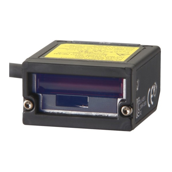
Page 20: Part Names
Laser alarm label (bottom side) Reading window Laser beam radiates from here Back side READ OK LED Illuminates when read correctly. TEST button Press it once to read once. Test Reading Function p.49 READ NG LED Illuminates when not read correctly. V500-R521B2/C2 User’s Manual... -
Page 21: Rating/Performance
Reading check Buzzer sound, indication LED Interface Communication specification RS-232C OK/NG output (Only V500-R521B2) NPN open collector output 24 VDC, 30 mA Function set method Menu sheet reading method or host command method Reading trigger External trigger (Transistor input) Trigger by command (RS-232C) - Page 22 80 to 150 mm 0.25 mm 60 to 170 mm 0.5 mm 60 to 230 mm 1.0 mm 60 to 270 mm Distance from the end of the case. Value at a reading angle 30 ° . V500-R521B2/C2 User’s Manual...
-
Page 23: Pitch Angle
Resolution = 0.25 mm, CODE39 (9 digits), MRD 63 % (PCS = 0.9) • Reading distance: 100 mm from the case end • Installation condition: Pitch angle α = 0 °, tilt angle γ = 0 °, curvature R = ∞ V500-R521B2/C2 User’s Manual... -
Page 24: Tilt Angle
Resolution = 0.26 mm, EAN, MRD 63 % (PCS = 0.9) • Reading distance: 100 mm from the case end • Installation condition: Pitch angle α = 0 °, skew angle β = 15 °, tilt angle γ = 0 ° V500-R521B2/C2 User’s Manual... -
Page 25: Usage Flow Chart
Check that the bar code in subject can be read. p.49 Test Reading Function Investigate the reading timing and moving speed. p.38 Operation Flow Chart Set the reading condition corresponding to the purpose. p.56 Menu Sheet/Command List V500-R521B2/C2 User’s Manual... - Page 26 Setting related to sorting read In case of trouble: A bar code cannot be read correctly. I don't know the communication specification. p.120 Troubleshooting p.46 Communication Data Format I can't understand the operation flow. p.38 Operation Flow Chart V500-R521B2/C2 User’s Manual...
-
Page 27: Wiring And Installation
Section 2 Wiring and Installation This section explains about the wiring method and installation method of the bar code reader. Wiring Installation V500-R521B2/C2 User’s Manual... - Page 28 • Turn off the power switch before connecting or disconnecting a connector. • Use a wrist strap etc. to avoid electrostatic charge when you touch terminals and signal lines, to avoid damage due to static electricity. Wiring diagram V500-R521B2 (Cable output type) Signal Signal direction Wiring color...
- Page 29 One-shot system READ OK/NG signal is turned on during the preset time (one-shot time). One-shot time can be set from 10 to 100 ms (in 10 ms interval). You can select positive logic/ negative logic. Setting method p.75 V500-R521B2/C2 User’s Manual...
-
Page 30: Power Supply
(HIGH active) Negative logic (LOW active) Setting method p.57 Trigger ON You can select the output logic of READ OK and READ NG signal. Power supply Recommended parts for the power supply Manufacturer Model OMRON Corporation S8VS-01505 V500-R521B2/C2 User’s Manual... - Page 31 Terminal voltage Von when a 1.3 V transistor is turned on Terminal voltage Voff when a 2.5 V transistor is turned off Output circuit of the READ OK/NG signal (Only V500-R521B2) OK/NG Internal circuit Item Specification Output system NPN open collector...
-
Page 32: Installation
Use the associated screw to install the insulation board. • Do not apply stress on the cable when installing or using. • Distance and angle allowed to read differs according the bar code. Check if the used bar code can be read actually, before installing. V500-R521B2/C2 User’s Manual... - Page 33 Dimension of mounting hole Bar code label Laser beam Insulation board (accessory) Material: Fabric bake (Unit: mm) 2-M5 holes When the associated mounting bracket and insulation board are not used, install it by referring to the outline dimension figure. p.114 V500-R521B2/C2 User’s Manual...
-
Page 34: Function Explanation
Section 3 Function Explanation This section explains about representative functions of the bar code reader. Explanation of Reading System Operation Flow Chart Communication Data Format Test Reading Function V500-R521B2/C2 User’s Manual... -
Page 35: Explanation Of Reading System
700 ms. E.g. 3: When you want to set the effective duration to 10.0 sec., set the effective duration to 10 sec. and the minor setting to 0 ms. Effective duration setting method p.70 V500-R521B2/C2 User’s Manual... - Page 36 In case of single reading and plural reading: When reading succeeded: OK signal is output. When reading failed: NG signal is output. In case of continuous reading: OK or NG signal after reading is not output. READ OK/NG signal output p.28 V500-R521B2/C2 User’s Manual...
-
Page 37: Operation Flow Chart
Process when reading succeeded When the trigger by a command is used, ignore this clause. In case of trigger controlled system (reads while the trigger is ON), consider that the reading effective duration is set to 0. V500-R521B2/C2 User’s Manual... - Page 38 Process when reading failed When the trigger by a command is used, ignore this clause. In case of trigger controlled system (reads while the trigger is ON), consider that the reading effective duration is set to 0. V500-R521B2/C2 User’s Manual...
- Page 39 Process when reading failed When the trigger by a command is used, ignore this clause. In case of trigger controlled system (reads while the trigger is ON), consider that the reading effective duration is set to 0. V500-R521B2/C2 User’s Manual...
- Page 40 When NAK (15H) 1 byte is received from the upper equipment data is transmitted again. When the time-up time comes which is set beforehand, the time-up buzzer sounds and the data transmission ends. Bar code reader V500-R521 Data Data Data Upper equipment V500-R521B2/C2 User’s Manual...
- Page 41 (Data length) + (1: In case when parity exists) + (Number of stop bit) (Number of digit of transmission data + Communication Number of header characters + time (ms) = (Communication speed) Number of footer characters) x 10 V500-R521B2/C2 User’s Manual...
- Page 42 (Data length) + (1: In case when parity exists) + (Number of digit of transmission data + Communication (Number of stop bit) Number of header characters + time (ms) = (Communication speed) Number of footer characters) x 10 V500-R521B2/C2 User’s Manual...
- Page 43 When the timing is too slow... The bar code is already passed and cannot read. Photoelectronic sensor Checking the tack timing In case when bar codes come continuously, calculate how close the bar codes may come, considering above two points. V500-R521B2/C2 User’s Manual...
- Page 44 Whole height of a bar code is scanned. In case of tall size label, this direction is stable. A part of the height of a bar code is scanned. In case of short size label, this direction is stable. V500-R521B2/C2 User’s Manual...
-
Page 45: Communication Data Format
Reading trigger command format is as shown below. Set command input Reading condition set command can be transmitted from the upper equipment. Format is as follows. Command (In case of one character, m1 only) For details of command, refer to Section 4. p.56 V500-R521B2/C2 User’s Manual... - Page 46 – [STX]?[ETX], [STX]>[ETX] is transferred When it is judged as no bar code >: In cases other than above ?[CR], >[CR] are transferred [CAN] [CR] are transferred – [STX] [CAN] [ETX] are transferred – Setting method p.68 V500-R521B2/C2 User’s Manual...
- Page 47 Add a control character "C1" (ASCII code 5D, 43, 31) which indicates EAN 128, at the head of the transfer data. Also, FNC1 character, as a separating character, is replaced to GS (ASCII code 1DH) character and transferred. Setting method p.63 V500-R521B2/C2 User’s Manual...
-
Page 48: Test Reading Function
(Reading rate of every one sec. is measured according to the reading condition of factory default.) To finish the reading rate measurement mode, enter reset command "Z1" or re-start the bar code reader. Return to the normal measurement mode. V500-R521B2/C2 User’s Manual... -
Page 49: Output Format
Reading is not stable. Check if there is no dirt or lack on the bar code. 0~25 % Check if the installation location and angle of the bar code reader is appropriate once more. LED indication : Lights out : Blink : Illuminate V500-R521B2/C2 User’s Manual... - Page 50 Section 4 Setting Method This section explains about setting methods using a menu sheet and entering command from the upper equipment. How to Use Menu Sheet/Command Menu Sheet/Command List V500-R521B2/C2 User’s Manual...
-
Page 51: Setting Method
Read the item on the menu sheet you want to change setting. Menu Sheet/Command List p.56 To finish setting, read "Z7" on the menu sheet for setting start/end, again. Buzzer sound stops and returns to normal mode. V500-R521B2/C2 User’s Manual... - Page 52 You can create a menu sheet using bar code creation software available in the market, as shown below. E.g.: When creating a menu sheet "A3" Create "* A3 *" and cut the parts of "*" with scissors to create the menu sheet "A3". Cutting off section Cutting off section V500-R521B2/C2 User’s Manual...
- Page 53 Transmits "Z2", in order to write the set data on the nonvolatile memory in the bar code reader. Be sure to write when a condition is set by inputting command from the upper equipment. When you turn off the power without writing the setting in the memory, the set content may be deleted. V500-R521B2/C2 User’s Manual...
- Page 54 E.g. 3: Reading number of digit is set to "8-digit" and "12-digit". Transmit the number of digit command "A". Transmit "8-digit". (Input in decimal number. Numbers are fix to 2-digit.) Transmit the number of digit command "B". Transmit "12-digit". (Input in decimal number. Numbers are fix to 2-digit.) V500-R521B2/C2 User’s Manual...
-
Page 55: Menu Sheet/Command List
Setting related to communication condition p.77 Setting related to communication protocol p.78 Setting for header, footer and number of reading digit p.79 Setting related to test reading p.79 Direct code designation p.80 Setting related to sorting read p.83 V500-R521B2/C2 User’s Manual... -
Page 56: Setting Start/End According To Menu Sheets
Command Reset Setting related to external trigger signal Select positive logic/negative logic of the external trigger signal. Menu sheet Command External trigger signal Positive logic (H active) External trigger signal Negative logic (L active) (Factory default setting) V500-R521B2/C2 User’s Manual... -
Page 57: Return To Factory Default Setting
Buzzer sound duration after decoding is 200 ms. W5 Buzzer sound volume Max. Buzzer frequency 3 kHz, 2 kHz External trigger signal Negative logic (L active) READ OK/NG signal output Output READ OK/NG signal output system Trigger synchronous system, positive logic (H active) V500-R521B2/C2 User’s Manual... -
Page 58: Collective Setting
Buzzer sound duration after decoding is 200 ms. W5 Buzzer sound volume Max. Buzzer frequency 3 kHz, 2 kHz External trigger signal Negative logic (L active) READ OK/NG signal output Output READ OK/NG signal output system Trigger synchronous system, positive logic (H active) V500-R521B2/C2 User’s Manual... - Page 59 Buzzer sound duration after decoding is 200 ms. W5 Buzzer sound volume Max. Buzzer frequency 3 kHz, 2 kHz External trigger signal Negative logic (L active) READ OK/NG signal output Output READ OK/NG signal output system Trigger synchronous system, positive logic (H active) V500-R521B2/C2 User’s Manual...
-
Page 60: Setting Of Reading Permission And Prohibition
Reading permission for NW-7 (Factory default setting) Reading permission only for ITF Reading permission for ITF (Factory default setting) Reading permission only for STF Reading permission for STF (Factory default setting) Reading permission only for CODE93 Reading permission for CODE93 V500-R521B2/C2 User’s Manual... - Page 61 Reading prohibition for EAN/UPC Reading prohibition for CODE39 Reading prohibition for NW-7 Reading prohibition for STF Reading prohibition for ITF Reading prohibition for CODE93 (Factory default setting) Reading prohibition for CODE128 (Factory default setting) Reading prohibition for all types V500-R521B2/C2 User’s Manual...
-
Page 62: Detail Setting For Reading Code
Output UPC-E in 6-digit (without 0 in the beginning) the beginning or C/D) CODE39 Menu sheet Command Menu sheet Command Invalid C/D of CODE39 Not transfer ST/SP of CODE39 (Factory default setting) Valid C/D of CODE39 Transfer ST/SP of CODE39 (Factory default setting) V500-R521B2/C2 User’s Manual... - Page 63 Valid C/D of NW-7 (modulus 16) Transfer ST/SP of NW-7 (abcd/abcd) (Factory default setting) Transfer C/D of NW-7 NW-7 1-digit reading permission (Factory default setting) Not transfer C/D of NW-7 NW-7 1-digit reading prohibition (Factory default setting) Not transfer ST/SP of NW-7 V500-R521B2/C2 User’s Manual...
- Page 64 After executing CODE128 reading permission command (B6), execute commands as shown below. Menu sheet Command Menu sheet Command All reading permission including Reading permission only for EAN128 in EAN128 CODE128 (Factory default setting) EAN128 (Reading specification) p.126 V500-R521B2/C2 User’s Manual...
-
Page 65: Setting For Reading Conformance
Command Reading conformance twice Reading conformance 5 times (Verification: once) (Verification: 4 times) (Factory default setting) Reading conformance 3 times Reading conformance 6 times (Verification: 2 times) (Verification: 5 times) Reading conformance 4 times (Verification: 3 times) V500-R521B2/C2 User’s Manual... -
Page 66: Setting For Reading System
Explanation of Reading System p.36 Reading system Menu sheet Command Menu sheet Command Full-time reading Trigger reading (Factory default setting) Reading operation Menu sheet Command Menu sheet Command Single reading Continuous reading (Factory default setting) Plural reading V500-R521B2/C2 User’s Manual... -
Page 67: V500-R521B2/C2
When reading failed: Transfer BR [CR] When reading failed: Transfer [CAN] [CR] When reading failed: Transfer When reading failed: Transfer [STX] [STX]?[ETX], [STX]>[ETX] (*) [CAN] [ETX] When it is judged as no bar code:? In cases other than above: > V500-R521B2/C2 User’s Manual... -
Page 68: V500-R521B2/C2
After reading this menu sheet, read the bar code of the number of digit you want to register twice, continuously. When the number of digit is one type, set A and B to the same setting. After transmitting this command, transmit the character string of the bar code you want to register, continuously. p.54 V500-R521B2/C2 User’s Manual... -
Page 69: V500-R521B2/C2
Trigger + 3 sec. Trigger + 150 ms (minor setting) Trigger + 4 sec. Trigger + 200 ms (minor setting) Trigger + 6 sec. Trigger + 250 ms (minor setting) Trigger + 8 sec. Trigger + 300 ms (minor setting) V500-R521B2/C2 User’s Manual... -
Page 70: V500-R521B2/C2
Trigger + 600 ms (minor setting) Trigger + 450 ms (minor setting) Trigger + 650 ms (minor setting) Trigger + 500 ms (minor setting) Trigger + 700 ms (minor setting) Trigger + 550 ms (minor setting) Trigger + 750 ms (minor setting) V500-R521B2/C2 User’s Manual... -
Page 71: Setting Related To Led
LED does not illuminate after decode. The LED illuminates for 400 ms after decoding. The LED illuminates for 100 ms after The LED illuminates for 800 ms after decoding. decoding. The LED illuminates for 200 ms after decoding. (Factory default setting) V500-R521B2/C2 User’s Manual... -
Page 72: Settings Related To Duration Of Buzzer Sound And Volume
Buzzer sound volume; middle or below T2 Buzzer sound duration after decoding; 100 ms Buzzer sound volume; min. Buzzer sound duration after decoding; 200 ms (Factory default setting) No buzzer sound after decoding Buzzer sound duration after decoding; 400 ms V500-R521B2/C2 User’s Manual... - Page 73 Setting Method Buzzer frequency Menu sheet Command Menu sheet Command Buzzer sound frequency after Buzzer sound frequency after decoding; 3 kHz decoding; 2 kHz, 3 kHz Buzzer sound frequency after decoding; 3 kHz, 2 kHz (Factory default setting) V500-R521B2/C2 User’s Manual...
-
Page 74: Setting Related To Read Ok/Ng Signal Output (Only When V500-R521B2 Is Used)
Section 4 Setting Method Setting related to READ OK/NG signal output (Only when V500-R521B2 is used) When you want to output reading succeeded/failed to READ OK/NG signal, set the conditions of output system and duration, then execute "signal output (8Q)". - Page 75 Section 4 Setting Method Menu sheet Command Menu sheet Command Signal output one-shot duration 20 ms Signal output one-shot duration; 100 ms V500-R521B2/C2 User’s Manual...
-
Page 76: Setting Related To Communication Condition
Parity uneven number Communication speed; 9600 bps Stop bit; 1-bit (Factory default setting) (Factory default setting) Communication speed; 19200 bps Stop bit; 2-bit Communication speed; 38400 bps Without RS/CS control (Factory default setting) With RS/CS control (BUSY/READY) V500-R521B2/C2 User’s Manual... -
Page 77: Setting Related To Communication Protocol
ACK/NAK response waiting time: CS waiting time: 200 ms Infinite (Factory default setting) ACK/NAK response waiting time: 100 ms I5 CS waiting time: 400 ms ACK/NAK response waiting time: 500 ms I6 ACK/NAK response waiting time: 1000 ms V500-R521B2/C2 User’s Manual... -
Page 78: Setting For Header, Footer And Number Of Reading Digit
Collective setting of footer (Applied to Number of reading digit is transferred all codes) (Applied to all codes) Setting related to test reading Test reading function p.49 Menu sheet Command Mode enters to reading rate measurement mode. (No menu sheet) V500-R521B2/C2 User’s Manual... -
Page 79: Direct Code Designation
"J" is set. "C" is set. "K" is set. "D" is set. "L" is set. "E" is set. "M" is set. "F" is set. "N" is set. "G" is set. "O" is set. "H" is set. "P" is set. V500-R521B2/C2 User’s Manual... - Page 80 "0" is set. '"S" is set. "1" is set. "T" is set. "2" is set. "U" is set. "3" is set. "V" is set. "5" is set. "W" is set. "6" is set. "Y" is set. "7" is set. V500-R521B2/C2 User’s Manual...
- Page 81 Section 4 Setting Method Menu sheet Command Menu sheet Command "8" is set. ETX (03H) is set. "9" is set. CR (ODH) is set. STX (02H) is set LF (0AH) is set. V500-R521B2/C2 User’s Manual...
-
Page 82: Setting Related To Sorting Read
Communication Stop bit length 1-bit condition Header None Footer Transfer number of digits Not transferred RS/CS control None CS waiting time Infinity Communication protocol No protocol system Process when reading is NG No process (Nothing is transferred) V500-R521B2/C2 User’s Manual... - Page 83 [^A] One character negation designation (One character that is not A) [^A|B] One character negation designation (One character that is not A nor B) [^A-D] One character negation designation (One character that is not A to D) V500-R521B2/C2 User’s Manual...
- Page 84 Designation of character string "Z (direct code)" # 5 D CR Designation of character string "] (5DH)" # 2 1 CR Designation of character string "[ ! (21H)" # 0 0 CR Character string separation # 0 0 CR End of command V500-R521B2/C2 User’s Manual...
-
Page 85: Example Of System Configuration
Example of System Configuration This section explains about connection method with upper equipment. Example of Connection with a PC Example of Connection with Programmable Controller (CS1) Example of Multi-drop Connection How to Use Command Link Unit V700-L12 V500-R521B2/C2 User’s Manual... -
Page 86: Example Of Connection With A Pc
Bar code reader V500-R521C2 PC/AT compatible PC Special cable V509-W011D AC 100 V Power supply for bar code S8VS-01505 Wire (When V500-R521B2 is used) Upper equipment side Bar code reader side (Example of PC/AT compatible PC) Wiring Signal Signal Pin No. -
Page 87: Example Of Connection With Programmable Controller (Cs1)
Section 5 Example of System Configuration Example of Connection with Programmable Controller (CS1) Connection with programmable controller CS1 (Made by OMRON) is explained. Input unit CPU unit Programming C200H-ID212 Bar code reader Power supply unit CS1H-CPU64-V1 console V500-R521C2 C200HW-PA204S C200H-PRO27... - Page 88 For detail setting method, refer to the operation manual of your programmable controller. Setting item Setting content Dip switch of CPU unit PC system setting 160[8300] 161[0000] 164[000D] 165[0100] DM setting Set [1B5A] to DM00100. (Memorize "Z" of ASCII code) V500-R521B2/C2 User’s Manual...
- Page 89 DM00200 and displays the content on the #0000 programming console. A393 MSG (46) &0 DM0200 For the program command, refer to the operation manual of your programming console. (Items related to communication method by RS-232C nonprocedural system.) V500-R521B2/C2 User’s Manual...
-
Page 90: Example Of Multi-Drop Connection
PC/AT compatible PC Communication converter K3SC RS-232C RS-485 Communication link unit RS-485 RS-485 Machine Machine Machine V700-L12 No. 01 No. 03 No. 02 Power supply 24 VDC S8VS-03024 External trigger Special cable Input terminal V509-W019 Bar code reader V500-R521C2 V500-R521B2/C2 User’s Manual... - Page 91 ON (*) SW10 is ON In case of connection example shown here, termination resistors of the machine No. 3 and the upper equipment (interface converter) are turned ON. Specification and wiring of the link unit p.93 V500-R521B2/C2 User’s Manual...
- Page 92 Stores data Polling Data export of Machine Link unit No. 1 Returns data Polling Data export of Machine Link unit No. 2 Returns data Polling Data export of Machine Link unit No. 3 Returns data Data export V500-R521B2/C2 User’s Manual...
-
Page 93: Communication Format
E.g.: When the read data is not accumulated (Machine No.) (Check code) Code indicating that there is no data When the bar code reader setting is changed from the upper equipment ESC (m1) (m2) (Check code) (Machine No.) Command character string V500-R521B2/C2 User’s Manual... -
Page 94: How To Use Command Link Unit V700-L12
Illuminate in the event of a failure during data communication with upper equipment or a bar code reader. GR (frame ground) terminal is in the multi-connection port. D type grounding (former type 3 grounding) should be performed. V500-R521B2/C2 User’s Manual... - Page 95 It does not transmit the received reply to the upper equipment. • When inputting data from the ID port, it transmits to the upper equipment immediately. RS-485 termination resistance OFF (invalid) ON (valid) DIP-SW is used for setting each function. V500-R521B2/C2 User’s Manual...
- Page 96 6.0 mm or less Connect 24 V power supply device. Recommended device Manufacturer Model OMRON Corporation S8VS-03024 Confirmation should be fully made if there is no mistake after wiring. Faulty wiring may be the cause of failure. V500-R521B2/C2 User’s Manual...
- Page 97 • Through procedure (immediate transmission system): ON RS-485 termination OFF (invalid) Set whether to make RS-485 termination resistance valid. Turn resistance on the link unit on both sides of transmission path. (When only one set is connected, turn it ON.) V500-R521B2/C2 User’s Manual...
- Page 98 Cable length Max. 15 m Communication system In compliance with RS-232C Synchronous system Asynchronous system Communication control system One-to-N procedure dedicated to OMRON Communication speed 4800/9600/19200/38400 bps (Set with DIP-SW) Character format (fixed) Start bit Data bit Parity bit Stop bit...
- Page 99 Cable length should be 15 m or less. Recommended parts Model Manufacturer Cable CO-MA-VV-SB 5PX28AWG Hitachi Cable, Ltd. Connector Socket XM2D-0901 OMRON Corporation Hood XM2S-0913 OMRON Corporation Wiring method 1 Link unit PC/AT compatible PC D-SUB 9 pin D-SUB 9 pin Signal Signal Pin No.
- Page 100 Cable length Total length: Max. 1 km Communication system In compliance with RS-485 Synchronous system Asynchronous system Communication control system One-to-N procedure dedicated to OMRON Communication speed 4800/9600/19200/38400 bps (Set with DIP-SW) Character format (fixed) Start bit Data bit Parity bit...
- Page 101 Front side Compact slotted screwdriver, Recommended driver its tip is constant in thickness Manufacturer Model OMRON Corporation XW4Z-00C 0.6 mm 3.5 mm Connect the connector to the link unit. Fit the direction of the connector on the link unit side and the cable, insert firmly to the end and tighten the fixing screws.
- Page 102 5 V ±5 % supply Communication Communication In compliance with RS-232C part system Synchronous Asynchronous system system Communication One-to-one procedure dedicated to OMRON control system Communication 9600 bps speed (fixed) Character format Total Start bit Data bit Parity bit Stop bit...
- Page 103 Example of System Configuration Command specification Command to control the link unit (in case of one-to-N procedure dedicated to OMRON) is explained in this section. Transmit so that distance between each character of the command is less than 200 ms. When the distance is 200 ms or more, it is recognized as separation of commands.
- Page 104 In case of "Through procedure (normal output procedure)", no response is output even if command is input. Resend request (R) The response sent before is transmitted again. Input command (Check code) (Machine No.) Response Communication data with the bar code (same as immediately before) (Check code) (Machine No.) V500-R521B2/C2 User’s Manual...
- Page 105 Communication frame with the bar code is as shown below. Communication data with the bar code reader Control code indicating frame start Control code indicating frame end However, it returns to default ([CR] mode) when the power is turned on or off. V500-R521B2/C2 User’s Manual...
- Page 106 DIP-SW 1 to 5: Set to machine No. 1 Set to machine No. 2 Set to machine No. 3 With termination DIP-SW10: No termination No termination No termination resistance (ON) resistance (OFF) resistance (OFF) resistance (OFF) Total length: Max. 1 km V500-R521B2/C2 User’s Manual...
- Page 107 (OFF) resistance (ON) resistance (OFF) resistance (OFF) Total length: Max. 1 km The upper equipment should be in data reception condition within 15 ms after data transmission. This control should be performed for normal operation. V500-R521B2/C2 User’s Manual...
- Page 108 • RS signal control of the upper equipment (Turns OFF before ending command transmission) (*2) • RS signal control of the upper equipment (RS signal is always ON) (*2) • 24 VDC power source line check Upper connection port p.100 V500-R521B2/C2 User’s Manual...
- Page 109 Bar code reader • Cable wiring of the bar code reader (effect of circumference communication malfunction noise) Bar code reader malfunction • Connection of the interface connector to the bar code reader • Bar code reader cable disconnection V500-R521B2/C2 User’s Manual...
-
Page 110: Appendix
Section 6 Appendix External Dimension Troubleshooting ASCII Code Table Explanation of Terms Corresponding Bar Code List V500-R521B2/C2 User’s Manual... - Page 111 Section 6 Appendix External Dimension Bar code reader V500-R521B2 (Unit: mm) Light axis 2-M3 Depth 4.5 or less Vinyl insulated round cord φ3.8 9-core Black Standard length 2 m Laser beam Bar code label V500-R521B2/C2 User’s Manual...
- Page 112 Section 6 Appendix Bar code reader V500-R521C2 (Unit: mm) Light axis Connector 2-M3 Depth 4.5 or less Vinyl insulated round cord φ3.8 9-core Black Standard length 2 m Laser beam Bar code label V500-R521B2/C2 User’s Manual...
- Page 113 Section 6 Appendix Cable for programmable controller connection made by OMRON V509-W011 (Unit: mm) Vinyl insulated round cord φ5.1 Vinyl insulated round cord φ3.8, 3-core (conductor section area: D-sub 9 pin 0.2 mm , diameter of insulation body: φ1.0 mm)
- Page 114 Pink (external trigger) Brown (+5V) Blue (0V) Upper equipment side Bar code reader side D-sub 9 pin DIN 8 pin Signal name Shield cable No. Signal name TRIG Connector Shield wire Cover Shielded (External trigger) (+5V) (0V) V500-R521B2/C2 User’s Manual...
- Page 115 , diameter of insulation body: φ1.0 mm) Pink (external trigger) Blue (0V) Upper equipment side D-sub 9 pin Bar code reader side Signal name DIN 8 pin Shield cable No. Signal name TRIG Connector Shield wire Cover Shielded (External trigger) (0V) V500-R521B2/C2 User’s Manual...
- Page 116 Section 6 Appendix Communication link unit V700-L12 (Unit: mm) 2-φ4.5 Dimension of mounting hole process 2-M4 or φ4.2 V500-R521B2/C2 User’s Manual...
- Page 117 1. Check the operation of the upper unit side and the of the upper equipment operation manual. side correct? Change the bar code reader. (Or send it back to the manufacturer.) Troubleshooting when communication link unit is used p.110 V500-R521B2/C2 User’s Manual...
- Page 118 Section 6 Appendix ASCII Code Table Data Data Data Data Character (Hexadecim Character (Hexadecim Character (Hexadecim Character (Hexadecim al number) al number) al number) al number) " & – < ¥(\) > V500-R521B2/C2 User’s Manual...
-
Page 119: Explanation Of Terms
"Parity check" is a data check system which adds 1 bit to data and to have the total bit of "1" either in even number or odd number. The added 1 bit at this time is called "parity bit". V500-R521B2/C2 User’s Manual... - Page 120 4 9 0 1 2 3 4 Even digit 4 = 10 10 x 3 = 30 Odd digit = 13 30 + 13 = 43 (1st digit is 3) 10 - 3 = 7•••Check digit Therefore, data with check character is "49012347". V500-R521B2/C2 User’s Manual...
- Page 121 Numerical conversion 12 + 24 + 13 + 14 + 38 + 3 + 9 = 113 113 / 43 = 2 Remainder 27 (Character of 27 is R) R ... Check digit Therefore, data with check character is "CODE39R". V500-R521B2/C2 User’s Manual...
- Page 122 Numerical conversion 16 + 3 + 7 + 8 + 5 + 9 +17 = 65 65 / 16 = 4 Remainder 1 (Character of 1 is +) + ... Check digit Therefore, data with check character is "A37859B+". V500-R521B2/C2 User’s Manual...
- Page 123 When "All reading allowed including EAN (G5)" is set, CODE128 other than this combination can be read. Start pattern of EAN128 is converted to "C1" (5Dh43h31h in ASCII code) and output. "FNC1" (separator) indicating data separation is converted to "GS" and output. V500-R521B2/C2 User’s Manual...
-
Page 124: Corresponding Bar Code List
Section 6 Appendix Corresponding Bar Code List EAN, UPC CODE39 NW-7 CODE93 CODE128 V500-R521B2/C2 User’s Manual... - Page 125 Nonprocedural system Effective duration Nonvolatile memory Effective duration designation Number of conformance system Number of reading digits External dimension figure Number of verification External trigger signal 29 One-shot system Flow chart Output circuit Footer Output format Full-time reading V500-R521B2/C2 User's Manual...
- Page 126 Reading time Reading trigger Reading window Regular expression Reset RS/CS control RS-232C command Setting end Setting start Single reading Skew angle Slim bar Sort reading ST/SP Start code Stop bit Stop code Termination resistance TEST button Test reading V500-R521B2/C2 User's Manual...
-
Page 127: Revision History
P30: Changed model number of recommended parts. P33: Added information to diagram for insulation board. July 2008 P88, 89: “Wire (When V500-R521B2 is used)” is changed. P95: Changed DLE to ESC in example. P101: “Wiring method 2” is changed. P111: Changed end code.
Need help?
Do you have a question about the V500-R521B2 and is the answer not in the manual?
Questions and answers