Table of Contents
Advertisement
Quick Links
Advertisement
Table of Contents
Troubleshooting

Related Manuals for Supermicro SuperServer SYS-211E-FRN13P


Summary of Contents for Supermicro SuperServer SYS-211E-FRN13P
- Page 1 SuperServer ® SYS-211E-FRN13P SYS-211E-FRDN13P USER’S MANUAL Revision 1.0...
- Page 2 State of California, USA. The State of California, County of Santa Clara shall be the exclusive venue for the resolution of any such disputes. Supermicro's total liability for all claims will not exceed the price paid for the hardware product.
- Page 3 If you have any questions, please contact our support team at: support@supermicro.com This manual may be periodically updated without notice. Please check the Supermicro website for possible updates to the manual revision level. Secure Data Deletion A secure data deletion tool designed to fully erase all data from storage devices can be found on our website: https://www.supermicro.com/about/policies/disclaimer.cfm?url=/wdl/utility/...
-
Page 4: Table Of Contents
Preface Contents Chapter 1 Introduction 1.1 Overview ..........................9 1.2 System Features ........................10 Front View .........................10 Control Panel .........................12 Rear View ..........................13 1.3 System Architecture ......................14 Main Components ......................14 1.4 Motherboard Layout ......................15 Quick Reference Table ......................16 Motherboard Block Diagram .....................18 Chapter 2 Server Installation 2.1 Overview ..........................19 2.2 Preparing for Setup ......................19... - Page 5 Preface Chapter 3 Maintenance and Component Installation 3.1 Removing Power ........................31 3.2 Accessing the System ......................32 3.3 Static-Sensitive Devices ......................33 Precautions ........................33 3.4 Processor and Heatsink Installation ...................34 The 5th/4th Generation Intel Xeon Scalable Processor ...........34 Overview of the Processor Carrier Assembly ..............35 Overview of the CPU Socket ....................35 Overview of the Processor Heatsink Module ..............36 Creating the Processor Carrier Assembly .................37...
- Page 6 Preface Chapter 4 Motherboard Connections 4.1 Power Connections ......................59 4.2 Headers ..........................60 4.3 Input/Output Ports ......................64 4.4 Front Control Panel ......................65 4.5 Jumpers ..........................68 How Jumpers Work ......................68 4.6 LED Indicators ........................71 Chapter 5 Software 5.1 Microsoft Windows OS Installation ..................72 5.2 Driver Installation ........................74 5.3 SuperDoctor 5 ........................75...
- Page 7 Preface 7.6 CMOS Clear ........................89 7.7 Where to Get Replacement Components ................90 7.8 Reporting an Issue ......................90 Technical Support Procedures ..................90 Returning Merchandise for Service ...................90 Vendor Support Filing System ..................91 7.9 Feedback ..........................91 Appendix A Standardized Warning Statements for AC Systems Appendix B Standardized Warning Statements for DC Systems DC Power Disconnection ....................130 Hazardous Voltage or Energy Present on DC Power Terminals ........132...
- Page 8 San Jose, CA 95131 U.S.A. Tel: +1 (408) 503-8000 Fax: +1 (408) 503-8008 Email: marketing@supermicro.com (General Information) Sales-USA@supermicro.com (Sales Inquiries) Government_Sales-USA@supermicro.com (Gov. Sales Inquiries) support@supermicro.com (Technical Support) RMA@supermicro.com (RMA Support) Webmaster@supermicro.com (Webmaster) Website: www.supermicro.com Europe Address: Super Micro Computer B.V.
-
Page 9: Chapter 1 Introduction
Form Factor 2U: 17.2 x 3.5 x 11.8 in. / 436.88 x 88.9 x 298.8 mm (WxHxD) Note: A Quick Reference Guide can be found on the product page of the Supermicro website. The following safety models associated with SYS-211E-FRN13P/SYS-211E-FRDN13P have... -
Page 10: System Features
Chapter 1: Introduction 1.2 System Features The following views of the system display the main features. Refer to Appendix C for additional specifications. Front View 800 W Power Supplies Shared IPMI LAN Port Server Handle (PSU1, PSU2) Control Panel UID Button USB Ports GNSS + 1PPS VGA Port... - Page 11 Chapter 1: Introduction Expansion Slot Locations Slot Description One PCIe 5.0 x8 (LP/FHHL) *Optional: PCIe 5.0 x16 (LP/FHHL) One PCIe 5.0 x8 (LP/FHHL) Notes: • *Adjustments to the BIOS and cables are required. • FHFL = full-height, full-length. FHHL = full-height, half-length. HHHL = half-height, half- length.
-
Page 12: Control Panel
Chapter 1: Introduction Control Panel Power Button BMC Reset Power LED Drive Activity LED NIC (LAN2) LED NIC (LAN1) LED Power Fail LED Information LED Figure 1-3. Control Panel Control Panel Features Feature Description The main power switch applies or removes primary power from the power supplies to the Power Button server but maintains standby power. -
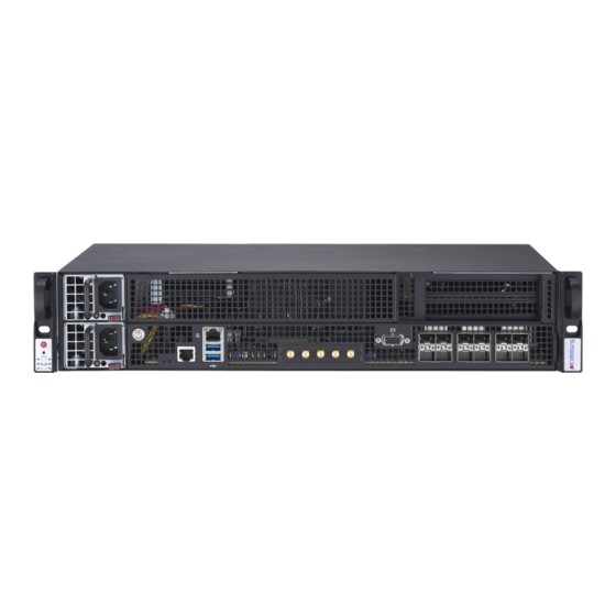
Page 13: Rear View
Chapter 1: Introduction Rear View Fans Figure 1-4. Rear View System Features: Rear Feature Description Fans Four (internal) 8-cm fans... -
Page 14: System Architecture
Chapter 1: Introduction 1.3 System Architecture This section shows the locations of the system's main components. Main Components System Fans Processor DIMM Slots Drive Bays Motherboard Riser Card Figure 1-5. Main Component Locations System Features: Top Feature Description System Fans Four internal fans (FAN-0220L4) Processor 5th/4th Gen Intel... -
Page 15: Motherboard Layout
Chapter 1: Introduction 1.4 Motherboard Layout Below is a layout of the X13SEVR-SP13F motherboard with the jumper, connector and LED locations shown. See the table on the following page for descriptions. For detailed descriptions, pinout information and jumper settings, refer to Chapter 4 or the Motherboard... -
Page 16: Quick Reference Table
Chapter 1: Introduction Quick Reference Table Jumper Description Default Setting JBT1 CMOS Clear Open (Normal) Pins 1-2 (Power Button On) JPF1 Power Force On Pins 2-3 (Force Power On) JPG1 VGA Enable/Disable Pins 1-2 (Enabled) JPL1 LAN1 Enable/Disable Pins 1-2 (Enabled) JPT1 Onboard TPM Module Enable/Disable Pins 1-2 (Enablled) - Page 17 Chapter 1: Introduction Connector Description MH1–MH5, MH8, MH10, Mounting Holes MH11 M.2_MH1 M.2 Mounting Hole SMA1 1PPS Input SMA2 10 MT/s Input SMA3 1PPS Output SMA4 10 MT/s Output SMA5 GNSS Antenna Input SRW1–SRW4 M.2 Mounting Holes...
-
Page 18: Motherboard Block Diagram
Chapter 1: Introduction Motherboard Block Diagram Front I/O SFP[0:3] SFP28 PCIe X8-Gen5 PCIe X8 E810-CAM1 MCIO x8 PE3[0–7] PE0[0–7] 25G*4 Front I/O SFP[0:3] SFP28 PCIe X8-Gen5 PCIe X8 E810-CAM1 PE3[8–15] PE1[0–7] 25G*4 MCIO x8 Front I/O PMD[0:3] SFP[0:3] SFP28 PCIe X4-Gen4 PCIe X8 E810-CAM1 PCIe x4 M.2... -
Page 19: Chapter 2 Server Installation
Chapter 2: Server Installation Chapter 2 Server Installation 2.1 Overview This chapter provides advice and instructions for mounting your system in a server rack. If your system is not already fully integrated with system memory etc., refer to Chapter 3 details on installing those specific components. -
Page 20: Server Precautions
Chapter 2: Server Installation • Always make sure the rack is stable before extending a server or other component from the rack. • You should extend only one server or component at a time - extending two or more simul- taneously may cause the rack to become unstable. -
Page 21: Mechanical Loading
Chapter 2: Server Installation Mechanical Loading Equipment should be mounted into a rack so that a hazardous condition does not arise due to uneven mechanical loading. Circuit Overloading Consideration should be given to the connection of the equipment to the power supply circuitry and the effect that any possible overloading of circuits might have on overcurrent protection and power supply wiring. -
Page 22: Installing The Rails
Chapter 2: Server Installation 2.3 Installing the Rails This section provides information on installing the SYS-211E-FRN13P/SYS-211E-FRDN13P into a rack unit with the rails provided. There are a variety of rack units on the market, which means that the assembly procedure will slightly differ from the instructions provided. You should also refer to the installation instructions that came with the rack unit you are using. - Page 23 Chapter 2: Server Installation Assembling the Inner and Outer Rails 1. Identify the left and right outer rails. Begin by assembling the left outer rail set. 2. Align the rear side of the long outer rail with the short outer rail. Ensure that the locking screw on the shorter rail fits between the longer rail.
-
Page 24: Locking Tabs
Chapter 2: Server Installation Locking Tab Figure 2-4. Identifying the Locking Tab on the Inner Rail Locking Tabs The inner rails have a locking tab. These tabs lock the server in place when fully extended from the rack. This prevents the server from coming completely out of the rack when you pull it out for servicing. -
Page 25: Installing The Inner Rails
Chapter 2: Server Installation 2.4 Installing the Inner Rails The inner rails can be installed onto the chassis without any tools. Inner Rail Holes Rear Front Figure 2-5. Installing the Inner Rails Installing the Inner Rails 1. Place the left inner rail on the side of the chassis aligning the hooks of the chassis with the inner rail holes. -
Page 26: Installing The Outer Rails To The Rack
Chapter 2: Server Installation 2.5 Installing the Outer Rails to the Rack Outer rails attach to the rack and hold the server in place. The outer rails for the chassis extend between 18 inches and 24 inches. Installing the Outer Rails to the Rack 1. -
Page 27: Installing The Server Into The Rack
Chapter 2: Server Installation 2.6 Installing the Server into the Rack Slide the chassis into the rack so that the bottom of the chassis slides onto the bottom lip of the rails, carefully aligning the left and right inner rails on the chassis to the matching outer rails on the rack. -
Page 28: Removing The Server From The Rack
Chapter 2: Server Installation Figure 2-8. Installing Front Screws onto the Rack Note: Figures are for illustrative purposes only. Always install servers to the bottom of a rack first. 2.7 Removing the Server from the Rack To remove the system from the rack, perform the installation steps in reverse. Removing the System 1. -
Page 29: Connecting Power And Ground In A Nebs Environment
Safety Ground, indicated by “Earth GND Symbol”. (Optional because Chassis GND stud is connected) • +Return, positive terminal (Battery Return, BR). Supermicro provides a cable for connection to the DC power supply. You should use the provided cable or an equivalent cable with the following specifications: • Positronic CBD connector. -
Page 30: Chassis Ground Stud Connections For Ac And Dc Systems
Chapter 2: Server Installation Chassis Ground Stud Connections for AC and DC Systems Both the AC and DC server products will include a chassis ground terminal as part of the chassis. This terminal is identified with the IEC 60417 #5019 Protective Earth Symbol. This equipment is designed to connect to the Common Bonding Network (CBN) of the facility in which it is installed. -
Page 31: Chapter 3 Maintenance And Component Installation
Chapter 3: Maintenance and Component Installation Chapter 3 Maintenance and Component Installation This chapter provides instructions on installing and replacing main system components. To prevent compatibility issues, only use components that match the specifications and/or part numbers given. Installation or replacement of most components require that power first be removed from the system. -
Page 32: Accessing The System
Chapter 3: Maintenance and Component Installation 3.2 Accessing the System The top cover is removable to access the system components. Removing the Top Cover 1. Remove the two screws. 2. Slide the cover back and off. Caution: Except for short periods of time, do not operate the server without the cover in place. The chassis cover must be in place to allow for proper airflow and to prevent overheating. -
Page 33: Static-Sensitive Devices
Chapter 3: Maintenance and Component Installation 3.3 Static-Sensitive Devices Electrostatic Discharge (ESD) can damage electronic components. To avoid damaging your motherboard, it is important to handle it very carefully. The following measures are generally sufficient to protect the system PCBs from ESD. Precautions •... -
Page 34: Processor And Heatsink Installation
Thermal grease is pre-applied on a new heatsink. No additional thermal grease is needed. • Refer to the Supermicro website for updates on processor support. • All graphics in this manual are for illustrations only. Your components may look different. -
Page 35: Overview Of The Processor Carrier Assembly
Chapter 3: Maintenance and Component Installation Overview of the Processor Carrier Assembly The processor carrier assembly contains the 5th/4th Generation Intel Xeon Scalable processor and a processor carrier. 1. Intel Xeon Scalable Processor 2. Processor Carrier Overview of the CPU Socket The CPU socket is protected by a plastic protective cover. -
Page 36: Overview Of The Processor Heatsink Module
Chapter 3: Maintenance and Component Installation Overview of the Processor Heatsink Module The Processor Heatsink Module (PHM) contains a heatsink, a processor carrier, and the 5th/4th Generation Intel Xeon Scalable processor. 1. Heatsink with Thermal Grease 2. Processor Carrier 3. Intel Xeon Scalable Processor Processor Heatsink Module (PHM) Bottom View... -
Page 37: Creating The Processor Carrier Assembly
Chapter 3: Maintenance and Component Installation Creating the Processor Carrier Assembly To install a processor into the processor carrier, follow the steps below: 1. Before installation, make sure the lever on the processor carrier is pressed down as shown below. 2. -
Page 38: Assembling The Processor Heatsink Module
Chapter 3: Maintenance and Component Installation Assembling the Processor Processor Carrier Assembly (Upside Down) Heatsink Module After creating the processor carrier Triangle on the CPU assembly for the processor, mount it onto the heatsink to create the processor heatsink module (PHM): 1. -
Page 39: Preparing The Cpu Socket For Installation
Chapter 3: Maintenance and Component Installation Preparing the CPU Socket for Installation This motherboard comes with a plastic protective cover installed on the CPU socket. Remove it from the socket to install the Processor Heatsink Module (PHM). Gently pull up one corner of the plastic protective cover to remove it. -
Page 40: Installing The Processor Heatsink Module
Chapter 3: Maintenance and Component Installation Installing the Processor Heatsink Module After assembling the Processor Heatsink Module (PHM), install it onto the CPU socket: 1. Align pin 1 of the PHM with the printed triangle on the CPU socket. See the left image below. -
Page 41: Removing The Processor Heatsink Module
Chapter 3: Maintenance and Component Installation Removing the Processor Heatsink Module Before removing the processor heatsink module (PHM) from the motherboard, shut down the system and then unplug the AC power cord from all power supplies. Then follow the steps below: 1. -
Page 42: Memory Support And Installation
Chapter 3: Maintenance and Component Installation 3.5 Memory Support and Installation Note: Check the Supermicro website for recommended memory modules. Important: Exercise extreme care when installing or removing DIMM modules to prevent any possible damage. Memory Support The X13SEVR-SP13F supports up to 2 TB of DDR5 ECC RDIMM (3DS) memory with speeds of up to 4800 MT/s in eight memory slots. -
Page 43: General Guidelines For Optimizing Memory Performance
Chapter 3: Maintenance and Component Installation General Guidelines for Optimizing Memory Performance • It's recommended to use DDR5 memory of the same type, size, and speed. • Mixed DIMM speeds can be installed. However, all DIMMs will run at the speed of the slowest DIMM. -
Page 44: Dimm Installation
Chapter 3: Maintenance and Component Installation DIMM Installation 1. Insert DIMM modules in the following order: DIMMA2, DIMMB2 and then DIMMA1, DIMMB1. 2. Push the release tabs outwards on both ends of the DIMM slot to unlock it. Notches 3. Align the key of the DIMM module with the receptive point on the memory slot. -
Page 45: Motherboard Battery
Chapter 3: Maintenance and Component Installation 3.6 Motherboard Battery The motherboard uses non-volatile memory to retain system information when system power is removed. This memory is powered by a lithium battery residing on the motherboard. Replacing the Battery Begin by removing the top cover from the system. 1. -
Page 46: Storage Drives
The CSE-221M chassis supports up to two 2.5" storage drives in drive carriers to simplify their removal from the chassis. These carriers also help promote proper airflow. Note: Enterprise level storage are recommended for use in Supermicro chassis and servers. For information on recommended storage, visit the Supermicro website at https://www. -
Page 47: Installing Drives
Chapter 3: Maintenance and Component Installation Installing Drives Removing Drive Carriers from the Chassis 1. Remove the top chassis cover as described in Section 3.2. 2. Remove the drive's top screws and pull the drive bracket out of the chassis. Figure 3-4. - Page 48 Chapter 3: Maintenance and Component Installation 4. Insert the SSD 2 in the bracket and tighten the four screws. Figure 3-6. Installing SSD 2 in the Bracket 5. Install the bracket back in the chassis, tighten the screws, and connect the SATA cables. Caution: Except for short periods of time (swapping drives), do not operate the server with the drive carriers removed from the bays, regardless of how many drives are installed, for proper airflow.
-
Page 49: Installing M.2 Solid State Drives
Chapter 3: Maintenance and Component Installation Installing M.2 Solid State Drives The X13SEVR-SP13F supports PCIe 5.0 x2 NVMe M.2 SSD 2280. The M.2 slot supports the 2280 form factor. Installing M.2 Drives 1. Remove power from the system and then remove the top cover as described in Sections 3.1 and 3.2. -
Page 50: Expansion Cards
Chapter 3: Maintenance and Component Installation 3.8 Expansion Cards The system supports one bracket to install an expansion card. Riser Card Figure 3-7. Expansion Bracket Locations Riser Card Part Number Feature Riser Card Part Number Riser Card RSC-S-68G5... -
Page 51: Installing Expansion Cards Inte The Bracket
Chapter 3: Maintenance and Component Installation Installing Expansion Cards inte the Bracket Both slots 1 and 2 can accommodate PCIe 5.0 x8 low-profile FHHL cards. Installing PCI Expansion Cards 1. Remove the top cover. 2. Remove the card bracket from the chassis by unscrewing the screw holding the bracket indicated in the figure below. - Page 52 Chapter 3: Maintenance and Component Installation Figure 3-9. PCIe Slots Slot and Cable Connection Configuration Bracket Slot MCIO Cable Riser Card Slot 1: PCIe 5.0 x8 CBL-MCIO-1218M5R JPCIE1A1 Default Setting Slot 2: PCIe 5.0 x8 CBL-MCIO-1213M5 JPCIE2A1 Slot 1: PCIe 5.0 x16 CBL-MCIO-1218M5R JPCIE1A1 Optional Setting...
-
Page 53: System Cooling
Chapter 3: Maintenance and Component Installation 3.9 System Cooling Four internal fans provide cooling to the system. Fan Replacement 1. Determine which fan is failing. If possible, use BMC. If not, remove the chassis cover while the power is on, and examine the fans to determine which one has failed. 2. -
Page 54: Air Shroud
Chapter 3: Maintenance and Component Installation Air Shroud The system requires air shrouds for each node to maximize airflow efficiency. Installing the Air Shroud 1. Turn off the power to the system, then remove the top cover as described in Sections 3.1 and 3.2. -
Page 55: Power Supply
The power supplies are auto-switching capable. If replacing a power supply, the system does not need to be powered down. New units can be ordered directly from Supermicro or authorized distributors. Replacing an AC Power Supply 1. - Page 56 Chapter 3: Maintenance and Component Installation Replacing a DC Power Supply 1. Use the system's remote management to find the failed power supply. 2. Check the power supply's LED. 3. Disconnect the power cord from the power strip or outlet. 4.
-
Page 57: Power Supply Leds
Blinking Amber: When blinking, indicates that the power supply has a warning condition and continues to operate. • Solid Amber: When illuminated, indicates that the power supply is plugged in, and is in an abnormal state. The system might need service. Please contact Supermicro technical support. Power Supply LED States LED Color... -
Page 58: Bmc Reset
Chapter 3: Maintenance and Component Installation 3.11 BMC Reset The BMC can be reset using the button on the front control panel or on the chassis rear. • Reset – Press and hold the button. After six seconds, the LED blinks at 2 Hz. The BMC resets and the reset duration is approximately 250 ms. -
Page 59: Chapter 4 Motherboard Connections
Chapter 4: Motherboard Connections Chapter 4 Motherboard Connections This section describes the connections on the motherboard and provides pinout definitions. Note that depending on how the system is configured, not all connections are required. The LEDs on the motherboard are also described here. A motherboard layout indicating component locations may be found in Chapter 1. -
Page 60: Headers
Port 80 connection. Use this header to enhance system performance and data security. Refer to the table below for pin definitions. Please go to the following link for more information on the TPM: http://www.supermicro.com/manuals/other/TPM.pdf. Trusted Platform Module Header Pin Definitions... - Page 61 Chapter 4: Motherboard Connections M.2 M-Key PCIe 4.0 Connector (2280) The motherboard has two M.2 slots at J11. M.2 was formerly known as Next Generation Form Factor (NGFF) and serves to replace mini PCIe. M.2 allows for a variety of card sizes, increased functionality, and spatial efficiency.
- Page 62 Chapter 4: Motherboard Connections COM Header The motherboard has one COM header that provides one serial connection (COM1) and supports RS-232 function. COM Port Pin Definitions Pin# Definition Pin# Definition Ground Standby Power The Standby Power header is located at JSTBY1 on the motherboard. You must have a card with a Standby Power connector and a cable to use this feature.
- Page 63 Chapter 4: Motherboard Connections Overheat LED Header Header JOH1 is used to connect to an LED indicator to provide warnings of chassis overheating and fan failure. This LED will blink when a fan failure occurs. Refer to the tables below for pin definitions. Overheat LED Header Overheat LED Header Status Pin Definitions...
-
Page 64: Input/Output Ports
Note: UID can also be triggered via IPMI on the motherboard. For more information on IPMI, please refer to the IPMI User's Guide posted on our website at https://www.supermicro.com/ support/manuals/. UID Button UID LED... -
Page 65: Front Control Panel
JF1 contains header pins for various buttons and indicators that are normally located on a control panel at the front of the chassis. These connectors are designed specifically for use with Supermicro chassis. See the figure below for the descriptions of the front control panel buttons and LED indicators. - Page 66 Chapter 4: Motherboard Connections Power Fail LED The Power Fail LED connection is located on pins 5 and 6 of JF1. Refer to the table below for pin definitions. Power Fail LED Pin Definitions (JF1) Pin# Definition 3.3 V Power Fail LED Overheat (OH)/Fan Fail and UID LED Connect an LED cable to pins 7 and 8 of the Front Control Panel to use the Overheat/Fan Fail LED connections.
- Page 67 Chapter 4: Motherboard Connections Power LED The Power LED connection is located on pins 15 and 16 of JF1. Refer to the table below for pin definitions. Power LED Pin Definitions (JF1) Pins Definition 3.3 Stby PWR LED NMI Button The non-maskable interrupt (NMI) button header is located on pins 19 and 20 of JF1.
-
Page 68: Jumpers
Chapter 4: Motherboard Connections 4.5 Jumpers How Jumpers Work To modify the operation of the motherboard, jumpers can be used to choose between optional settings. Jumpers create shorts between two pins to change the function of the connector. Pin 1 is identified with a square solder pad on the printed circuit board. Refer to the diagram below for an example of jumping pins 1 and 2. - Page 69 Chapter 4: Motherboard Connections LAN1 Enable/Disable Use jumper JPL1 to enable or disable LAN port 1. Refer to the table below for jumper settings. LAN1 Enable/Disable Jumper Settings Jumper Setting Definition Pins 1-2 Enabled (Default) Pins 2-3 Disabled TPM Enable Use JPT1 to enable or disable the onboard TPM2.0.
- Page 70 Chapter 4: Motherboard Connections SMA Voltage Level Selection Use jumper JSEL1 to select the SMA1–SMA4 voltage level. Refer to the table below for jumper settings. SMA Voltage Level Selection Jumper Settings Jumper Setting Definition Pins 1-2 3.3 V Pins 2-3...
-
Page 71: Led Indicators
Chapter 4: Motherboard Connections 4.6 LED Indicators Onboard Power LED LE1 is the onboard Power LED. When this LED is on, the system is on. Turn off the system and unplug the power cord before removing or installing components. Refer to the table below for more information. -
Page 72: Chapter 5 Software
1. Create a method to access the Microsoft Windows installation ISO file. That can be a USB flash, media drive, or the BMC KVM console. 2. Retrieve the proper RST/RSTe driver. Go to the Supermicro web page for your motherboard and click on "Download the Latest Drivers and Utilities", select the proper driver, and copy it to a USB flash drive. - Page 73 Chapter 5: Software 4. During Windows Setup, continue to the dialog where you select the drives on which to install Windows. If the disk you want to use is not listed, click on “Load driver” link at the bottom left corner. Figure 5-2.
-
Page 74: Driver Installation
The Supermicro website contains drivers and utilities for your system at https://www. supermicro.com/wdl/driver. Some of these must be installed, such as the chipset driver. After accessing the website, go into the CDR_Images (in the parent directory of the above link) and locate the ISO file for your motherboard. Download this file to a USB flash or media drive (you may also use a utility to extract the ISO file if preferred). -
Page 75: Superdoctor ® 5
5.3 SuperDoctor ® The Supermicro SuperDoctor 5 is a program that functions in a command-line or web-based interface for Windows and Linux operating systems. The program monitors such system health information as CPU temperature, system voltages, system power consumption, fan speed, and provides alerts via email or Simple Network Management Protocol (SNMP). -
Page 76: Bmc
There are several BIOS settings that are related to BMC. For general documentation and information on BMC, visit our website at: www.supermicro.com/en/solutions/management-software/bmc-resources BMC ADMIN User Password For security, each system is assigned a unique default BMC password for the ADMIN user. -
Page 77: Chapter 6 Optional Components
Chapter 6: Optional Components Chapter 6 Optional Components This chapter describes optional system components and installation procedures. 6.1 Optional Parts List Optional Parts List Description Part Number Cable for DB9 COM port CBL-CDAT-0605... -
Page 78: Chapter 7 Troubleshooting And Support
Chapter 7 Troubleshooting and Support 7.1 Information Resources Website A great deal of information is available on the Supermicro website, supermicro.com. Figure 7-1. Supermicro Website • Specifications for servers and other hardware are available by clicking the Products option. •... -
Page 79: Baseboard Management Controller (Bmc)
Security Center for recent security notices Supermicro Phone and Addresses 7.2 Baseboard Management Controller (BMC) The system supports the Baseboard Management Controller (BMC). BMC is used to provide remote access, monitoring and management. There are several BIOS settings that are related to BMC. -
Page 80: Troubleshooting Procedures
Chapter 7: Troubleshooting and Support 7.3 Troubleshooting Procedures Use the following procedures to troubleshoot your system. If you have followed all of the procedures below and still need assistance, refer to the Technical Support Procedures Returning Merchandise for Service section(s) in this chapter. Power down the system before changing any non hot-swap hardware components. -
Page 81: No Video
• Memory: Make sure that the memory modules are supported. Refer to the product page on our website at www.supermicro.com. Test the modules using memtest86 or a similar utility. • Storage drives: Make sure that all drives work properly. Replace if necessary. - Page 82 Also check the Control panel Overheat LED. • Adequate power supply: Make sure that the power supply provides adequate power to the system. Make sure that all power connectors are connected. Refer to the Supermicro website for the minimum power requirements. •...
-
Page 83: Crash Dump Using Bmc
In the event of a processor internal error (IERR) that crashes your system, you may want to provide information to support staff. You can download a crash dump of status information using BMC. The BMC manual is available at https://www.supermicro.com/en/solutions/ management-software/bmc-resources. Check BMC Error Log 1. -
Page 84: Uefi Bios Recovery
Warning: Do not upgrade the BIOS unless your system has a BIOS-related issue. Flashing the wrong BIOS can cause irreparable damage to the system. In no event shall Supermicro be liable for direct, indirect, special, incidental, or consequential damages arising from a BIOS update. - Page 85 USB flash or media drive.. Note 1: If you cannot locate the "Super.ROM" file in your drive disk, visit our website at www.supermicro.com to download the BIOS package. Extract the BIOS binary image into a USB flash device and rename it "Super.ROM" for the BIOS recovery use.
- Page 86 Chapter 7: Troubleshooting and Support Note: At this point, you may decide if you want to start the BIOS recovery. If you decide to proceed with BIOS recovery, follow the procedures below. 4. When the screen as shown above displays, use the arrow keys to select the item "Proceed with flash update"...
- Page 87 Chapter 7: Troubleshooting and Support 7. Press <Del> continuously during system boot to enter the BIOS Setup utility. From the top of the tool bar, select Boot to enter the submenu. From the submenu list, select Boot Option #1 as shown below. Then, set Boot Option #1 to [UEFI AP:UEFI: Built-in EFI Shell]. Press <F4>...
- Page 88 Chapter 7: Troubleshooting and Support Note: Do not interrupt this process until the BIOS flashing is complete. 9. The screen above indicates that the BIOS update process is complete. When you see the screen above, unplug the AC power cable from the power supply, clear CMOS, and plug the AC power cable in the power supply again to power on the system.
-
Page 89: Cmos Clear
Chapter 7: Troubleshooting and Support 7.6 CMOS Clear JBT1 is used to clear CMOS, which will also clear any passwords. Instead of pins, this jumper consists of contact pads to prevent accidentally clearing the contents of CMOS. To Clear CMOS 1. -
Page 90: Where To Get Replacement Components
7.7 Where to Get Replacement Components If you need replacement parts for your system, to ensure the highest level of professional service and technical support, purchase exclusively from our Supermicro Authorized Distributors/System Integrators/Resellers. A list can be found at: http://www.supermicro.com. -
Page 91: Vendor Support Filing System
For issues related to Red Hat Enterprise Linux, since it is a subscription based OS, contact your account representative. 7.9 Feedback Supermicro values your feedback as we strive to improve our customer experience in all facets of our business. Please email us at techwriterteam@supermicro.com to provide feedback on our manuals. -
Page 92: Appendix A Standardized Warning Statements For Ac Systems
Supermicro's Technical Support department for assistance. Only certified technicians should attempt to install or configure components. Read this appendix in its entirety before installing or configuring components in the Supermicro chassis. These warnings may also be found on our website at http://www.supermicro.com/about/... - Page 93 Appendix A: Warning Statements Warnung WICHTIGE SICHERHEITSHINWEISE Dieses Warnsymbol bedeutet Gefahr. Sie befinden sich in einer Situation, die zu Verletzungen führen kann. Machen Sie sich vor der Arbeit mit Geräten mit den Gefahren elektrischer Schaltungen und den üblichen Verfahren zur Vorbeugung vor Unfällen vertraut. Suchen Sie mit der am Ende jeder Warnung angegebenen Anweisungsnummer nach der jeweiligen Übersetzung in den übersetzten Sicherheitshinweisen, die zusammen mit diesem Gerät ausgeliefert wurden.
- Page 94 Appendix A: Warning Statements . ٌ ا ك ً ف حالة و ٌ يك أى تتسبب ف اصابة جسذ ة ٌ هذا الزهز ع ٌ خطز !تحذ ز قبل أى تعول عىل أي هعذات،يك عىل علن بالوخاطز ال ا ٌجوة عي الذوائز ٍ...
- Page 95 Appendix A: Warning Statements Warnung Vor dem Anschließen des Systems an die Stromquelle die Installationsanweisungen lesen. ¡Advertencia! Lea las instrucciones de instalación antes de conectar el sistema a la red de alimentación. Attention Avant de brancher le système sur la source d'alimentation, consulter les directives d'installation. .יש...
- Page 96 Appendix A: Warning Statements Warnung Dieses Produkt ist darauf angewiesen, dass im Gebäude ein Kurzschluss- bzw. Überstromschutz installiert ist. Stellen Sie sicher, dass der Nennwert der Schutzvorrichtung nicht mehr als: 250 V, 20 A beträgt. ¡Advertencia! Este equipo utiliza el sistema de protección contra cortocircuitos (o sobrecorrientes) del edificio.
- Page 97 Appendix A: Warning Statements Power Disconnection Warning Warning! The system must be disconnected from all sources of power and the power cord removed from the power supply module(s) before accessing the chassis interior to install or remove system components (except for hot-swap components). 電源切断の警告...
- Page 98 Appendix A: Warning Statements אזהרה מפני ניתוק חשמלי !אזהרה יש לנתק את המערכת מכל מקורות החשמל ויש להסיר את כבל החשמלי מהספק .לפני גישה לחלק הפנימי של המארז לצורך התקנת או הסרת רכיבים يجب فصم اننظاو من جميع مصادر انطاقت وإ ز انت سهك انكهرباء من وحدة امداد انطاقت...
- Page 99 Appendix A: Warning Statements Attention Seul le personnel autorisé et le personnel de maintenance qualifié doivent être autorisés à installer, remplacer ou entretenir cet équipement.. !אזהרה .יש לאפשר רק צוות מורשה ואנשי שירות מוסמכים להתקין, להחליף או לטפל בציוד זה .ينبغي...
- Page 100 Appendix A: Warning Statements Warnung Diese Einheit ist zur Installation in Bereichen mit beschränktem Zutritt vorgesehen. Der Zutritt zu derartigen Bereichen ist nur mit einem Spezialwerkzeug, Schloss und Schlüssel oder einer sonstigen Sicherheitsvorkehrung möglich. ¡Advertencia! Esta unidad ha sido diseñada para instalación en áreas de acceso restringido. Sólo puede obtenerse acceso a una de estas áreas mediante la utilización de una herramienta especial, cerradura con llave u otro medio de seguridad.
- Page 101 Appendix A: Warning Statements Battery Handling CAUTION: There is risk of explosion if the battery is replaced by an incorrect type. Replace the battery only with the same or equivalent type recommended by the manu- facturer. Dispose of used batteries according to the manufacturer's instructions 電池の取り扱い...
- Page 102 Appendix A: Warning Statements .هناك خطر االنفجار إذا تم استبدال البطارية بنوع غري صحيح اسحبذال البطارية فقط بنفس النىع أو ما يعادلها مام أوصث به الرشمة املصنعة جخلص من البطاريات املسحعملة وفقا لحعليامت الرشمة الصانعة 경고! 배터리를 잘못된 종류로 교체하면 폭발의 위험이 있습니다. 기존 배터리와 동일하거나 제조 사에서...
- Page 103 Appendix A: Warning Statements ¡Advertencia! Puede que esta unidad tenga más de una conexión para fuentes de alimentación. Para cortar por completo el suministro de energía, deben desconectarse todas las conexiones. Attention Cette unité peut avoir plus d'une connexion d'alimentation. Pour supprimer toute tension et tout courant électrique de l'unité, toutes les connexions d'alimentation doivent être débranchées.
- Page 104 Appendix A: Warning Statements Backplane Voltage Warning! Hazardous voltage or energy is present on the backplane when the system is operating. Use caution when servicing. バックプレーンの電圧 システムの稼働中は危険な電圧または電力が、 バックプレーン上にかかっています。 修理する際には注意く ださい。 警告 当系统正在进行时,背板上有很危险的电压或能量,进行维修时务必小心。 警告 當系統正在進行時,背板上有危險的電壓或能量,進行維修時務必小心。 Warnung Wenn das System in Betrieb ist, treten auf der Rückwandplatine gefährliche Spannungen oder Energien auf.
- Page 105 Appendix A: Warning Statements هناك خطز مه التيار الكهزبايئ أوالطاقة املىجىدة عىل اللىحة عندما يكىن النظام يعمل كه حذ ر ا عند خدمة هذا الجهاس 경고! 시스템이 동작 중일 때 후면판 (Backplane)에는 위험한 전압이나 에너지가 발생 합니다. 서비스 작업 시 주의하십시오. Waarschuwing Een gevaarlijke spanning of energie is aanwezig op de backplane wanneer het systeem in gebruik is.
- Page 106 Appendix A: Warning Statements תיאום חוקי החשמל הארצי !אזהרה .התקנת הציוד חייבת להיות תואמת לחוקי החשמל המקומיים והארציים تركيب املعدات الكهربائية يجب أن ميتثل للقىاويه املحلية والىطىية املتعلقة بالكهرباء 경고! 현 지역 및 국가의 전기 규정에 따라 장비를 설치해야 합니다. Waarschuwing Bij installatie van de apparatuur moet worden voldaan aan de lokale en nationale elektriciteitsvoorschriften.
- Page 107 Appendix A: Warning Statements Attention La mise au rebut ou le recyclage de ce produit sont généralement soumis à des lois et/ou directives de respect de l'environnement. Renseignez-vous auprès de l'organisme compétent. סילוק המוצר !אזהרה .סילוק סופי של מוצר זה חייב להיות בהתאם להנחיות וחוקי המדינה التخلص...
- Page 108 Appendix A: Warning Statements Warnung Gefährlich Bewegende Teile. Von den bewegenden Lüfterblätter fern halten. Die Lüfter drehen sich u. U. noch, wenn die Lüfterbaugruppe aus dem Chassis genommen wird. Halten Sie Finger, Schraubendreher und andere Gegenstände von den Öffnungen des Lüftergehäuses entfernt.
- Page 109 Verbindungskabeln, Stromkabeln und/oder Adapater, die Ihre örtlichen Sicherheitsstandards einhalten. Der Gebrauch von anderen Kabeln und Adapter können Fehlfunktionen oder Feuer verursachen. Die Richtlinien untersagen das Nutzen von UL oder CAS zertifizierten Kabeln (mit UL/CSA gekennzeichnet), an Geräten oder Produkten die nicht mit Supermicro gekennzeichnet sind.
- Page 110 .قيرح وأ لطع يف ببستي دق ىرخأ تالوحمو تالباك يأ مادختسا .ميلسلا سباقلاو لصوملا مجح لبق نم ةدمتعملا تالباكلا مادختسا تادعملاو ةيئابرهكلا ةزهجألل ةمالسلا نوناق رظحيUL وأCSA ( ةمالع لمحت يتلاوUL/CSA) لبق نم ةددحملاو ةينعملا تاجتنملا ريغ ىرخأ تادعم يأ عمSupermicro.
- Page 111 사항을 준수하여 제공되거나 지정된 연결 혹은 구매 케이블, 전원 케이블 및 AC 어댑터를 사용하십시오. 다른 케이블이나 어댑터를 사용하면 오작동이나 화재가 발생할 수 있습니다. 전기 용품 안전법은 UL 또는 CSA 인증 케이블 (코드에 UL / CSA가 표시된 케이블)을 Supermicro 가 지정한 제품 이외의 전기 장치에 사용하는 것을 금지합니다. Stroomkabel en AC-Adapter...
-
Page 112: Appendix B Standardized Warning Statements For Dc Systems
Supermicro's Technical Support department for assistance. Only certified technicians should attempt to install or configure components. Read this appendix in its entirety before installing or configuring components in the Supermicro chassis. These warnings may also be found on our website at http://www.supermicro.com/about/... - Page 113 Appendix B: Standardized Warning Statements Warnung WICHTIGE SICHERHEITSHINWEISE Dieses Warnsymbol bedeutet Gefahr. Sie befinden sich in einer Situation, die zu Verletzungen führen kann. Machen Sie sich vor der Arbeit mit Geräten mit den Gefahren elektrischer Schaltungen und den üblichen Verfahren zur Vorbeugung vor Unfällen vertraut. Suchen Sie mit der am Ende jeder Warnung angegebenen Anweisungsnummer nach der jeweiligen Übersetzung in den übersetzten Sicherheitshinweisen, die zusammen mit diesem Gerät ausgeliefert wurden.
- Page 114 Appendix B: Standardized Warning Statements . ٌ ا ك ً ف حالة و ٌ يك أى تتسبب ف اصابة جسذ ة ٌ هذا الزهز ع ٌ خطز !تحذ ز قبل أى تعول عىل أي هعذات،يك عىل علن بالوخاطز ال ا ٌجوة عي الذوائز ٍ...
- Page 115 Appendix B: Standardized Warning Statements Warnung Vor dem Anschließen des Systems an die Stromquelle die Installationsanweisungen lesen. ¡Advertencia! Lea las instrucciones de instalación antes de conectar el sistema a la red de alimentación. Attention Avant de brancher le système sur la source d'alimentation, consulter les directives d'installation. .יש...
- Page 116 Appendix B: Standardized Warning Statements Warnung Dieses Produkt ist darauf angewiesen, dass im Gebäude ein Kurzschluss- bzw. Überstromschutz installiert ist. Stellen Sie sicher, dass der Nennwert der Schutzvorrichtung nicht mehr als: 60VDC, 20A beträgt. ¡Advertencia! Este equipo utiliza el sistema de protección contra cortocircuitos (o sobrecorrientes) del edificio.
- Page 117 Appendix B: Standardized Warning Statements Power Disconnection Warning Warning! The system must be disconnected from all sources of power and the power cord removed from the power supply module(s) before accessing the chassis interior to install or remove system components (except for hot-swap components). 電源切断の警告...
- Page 118 Appendix B: Standardized Warning Statements يجب فصم اننظاو من جميع مصادر انطاقت وإ ز انت سهك انكهرباء من وحدة امداد انطاقت قبم انىصىل إىن امنناطق انداخهيت نههيكم نتثبيج أو إ ز انت مكىناث الجهاز 경고! 시스템에 부품들을 장착하거나 제거하기 위해서는 섀시 내부에 접근하기 전에 반드시 전원 공급장치로부터...
- Page 119 Appendix B: Standardized Warning Statements Attention Il est vivement recommandé de confier l'installation, le remplacement et la maintenance de ces équipements à des personnels qualifiés et expérimentés. !אזהרה .צוות מוסמך בלבד רשאי להתקין, להחליף את הציוד או לתת שירות עבור הציוד واملدربيه...
- Page 120 Appendix B: Standardized Warning Statements Warnung Diese Einheit ist zur Installation in Bereichen mit beschränktem Zutritt vorgesehen. Der Zutritt zu derartigen Bereichen ist nur mit einem Spezialwerkzeug, Schloss und Schlüssel oder einer sonstigen Sicherheitsvorkehrung möglich. ¡Advertencia! Esta unidad ha sido diseñada para instalación en áreas de acceso restringido. Sólo puede obtenerse acceso a una de estas áreas mediante la utilización de una herramienta especial, cerradura con llave u otro medio de seguridad.
- Page 121 Appendix B: Standardized Warning Statements Battery Handling CAUTION: There is risk of explosion if the battery is replaced by an incorrect type. Replace the battery only with the same or equivalent type recommended by the manu- facturer. Dispose of used batteries according to the manufacturer's instructions 電池の取り扱い...
- Page 122 Appendix B: Standardized Warning Statements .هناك خطر االنفجار إذا تم استبدال البطارية بنوع غري صحيح اسحبذال البطارية فقط بنفس النىع أو ما يعادلها مام أوصث به الرشمة املصنعة جخلص من البطاريات املسحعملة وفقا لحعليامت الرشمة الصانعة 경고! 배터리를 잘못된 종류로 교체하면 폭발의 위험이 있습니다. 기존 배터리와 동일하거나 제조 사에서...
- Page 123 Appendix B: Standardized Warning Statements ¡Advertencia! Puede que esta unidad tenga más de una conexión para fuentes de alimentación. Para cortar por completo el suministro de energía, deben desconectarse todas las conexiones. Attention Cette unité peut avoir plus d'une connexion d'alimentation. Pour supprimer toute tension et tout courant électrique de l'unité, toutes les connexions d'alimentation doivent être débranchées.
- Page 124 Appendix B: Standardized Warning Statements Backplane Voltage Warning! Hazardous voltage or energy is present on the backplane when the system is operating. Use caution when servicing. バックプレーンの電圧 システムの稼働中は危険な電圧または電力が、 バックプレーン上にかかっています。 修理する際には注意く ださい。 警告 当系统正在进行时,背板上有很危险的电压或能量,进行维修时务必小心。 警告 當系統正在進行時,背板上有危險的電壓或能量,進行維修時務必小心。 Warnung Wenn das System in Betrieb ist, treten auf der Rückwandplatine gefährliche Spannungen oder Energien auf.
- Page 125 Appendix B: Standardized Warning Statements هناك خطز مه التيار الكهزبايئ أوالطاقة املىجىدة عىل اللىحة عندما يكىن النظام يعمل كه حذ ر ا عند خدمة هذا الجهاس 경고! 시스템이 동작 중일 때 후면판 (Backplane)에는 위험한 전압이나 에너지가 발생 합니다. 서비스 작업 시 주의하십시오. Waarschuwing Een gevaarlijke spanning of energie is aanwezig op de backplane wanneer het systeem in gebruik is.
- Page 126 Appendix B: Standardized Warning Statements תיאום חוקי החשמל הארצי !אזהרה .התקנת הציוד חייבת להיות תואמת לחוקי החשמל המקומיים והארציים تركيب املعدات الكهربائية يجب أن ميتثل للقىاويه املحلية والىطىية املتعلقة بالكهرباء 경고! 현 지역 및 국가의 전기 규정에 따라 장비를 설치해야 합니다. Waarschuwing Bij installatie van de apparatuur moet worden voldaan aan de lokale en nationale elektriciteitsvoorschriften.
- Page 127 Appendix B: Standardized Warning Statements Attention La mise au rebut ou le recyclage de ce produit sont généralement soumis à des lois et/ou directives de respect de l'environnement. Renseignez-vous auprès de l'organisme compétent. סילוק המוצר !אזהרה .סילוק סופי של מוצר זה חייב להיות בהתאם להנחיות וחוקי המדינה التخلص...
- Page 128 Appendix B: Standardized Warning Statements Warnung Gefährlich Bewegende Teile. Von den bewegenden Lüfterblätter fern halten. Die Lüfter drehen sich u. U. noch, wenn die Lüfterbaugruppe aus dem Chassis genommen wird. Halten Sie Finger, Schraubendreher und andere Gegenstände von den Öffnungen des Lüftergehäuses entfernt.
- Page 129 Appendix B: Standardized Warning Statements DC Power Supply Warning! When stranded wiring is required, use approved wiring terminations, such as closedloop or spade-type with upturned lugs. These terminations should be the appropriate size for the wires and should clamp both the insulation and conductor. 警告...
-
Page 130: Dc Power Disconnection
Appendix B: Standardized Warning Statements وأ ةقلغم ةقلح لثم ،اهيلع ةقفاوملا ءاهنإ كالسألا مادختساو ،لبسلا مهب تعطقت نيذلا كالسألا ابولطم نوكي امدنع بجيو كالسألل بسانملا مجحلا نوكي تاءاهنإلا هذهل يغبنيو .ةبولقم تاورعلا عم عونلا ةيقيقحلا اهئامسأب ءايشألا .لصومو لزعلا نم لك حبك 주의! 꼬인... - Page 131 Appendix B: Standardized Warning Statements Warnung Vor Ausführung der folgenden Vorgänge ist sicherzustellen, daß die Gleichstromschaltung keinen Strom erhält. ¡Advertencia! Antes de proceder con los siguientes pasos, comprobar que la alimentación del circuito de corriente continua (CC) esté cortada (OFF). Attention Avant de pratiquer l'une quelconque des procédures ci-dessous, vérifier que le circuit en courant continu n'est plus sous tension.
-
Page 132: Hazardous Voltage Or Energy Present On Dc Power Terminals
Appendix B: Standardized Warning Statements Hazardous Voltage or Energy Present on DC Power Terminals Warning! Hazardous voltage or energy may be present on DC power terminals. Always replace cover when terminals are not in service. Be sure uninsulated conductors are not accessible when cover is in place. - Page 133 Appendix B: Standardized Warning Statements امدنع امئاد ءاطغ لادبتسا .ةمصاعلا ةقاطلا تاطحم ىلع ةدوجوم نوكت ةقاطلا وأ ةرطخلا دهجلا دق ءاطغلا امدنع اهيلإ لوصولا نكمي ال لوزعم ريغ تالصوملا هيف كش ال امم .ةمدخلا يف تسيل تاطحملا .هناكم يف 주의! DC전원...
-
Page 134: Appendix C System Specifications
Appendix C: System Specifications Appendix C System Specifications Processors Single 5th/4th Generation Intel Xeon Scalable processors in a Socket E (LGA-4677), supports up to 225 W TDP ® ® Chipset Intel C741 ® BIOS AMI 256 MB SPI Flash Memory Eight DIMM slots (1 DCP), up to 2 TB DDR5 5600 MT/s ECC RDIMM/LRDIMM Storage Drives Two 2.5”... - Page 135 Appendix C: System Specifications Operating Environment Operating Temperature: 0º to 40º C (32º to 104º F) Non-operating Temperature: -40º to 70º C (-40º to 158º F) Operating Relative Humidity: 8% to 90% (non-condensing) Non-operating Relative Humidity: 5% to 95% (non-condensing) Regulatory Compliance FCC, ICES, CE, VCCI, RCM, UKCA, NRTL, CB Applied Directives, Standards...
Need help?
Do you have a question about the SuperServer SYS-211E-FRN13P and is the answer not in the manual?
Questions and answers