Table of Contents
Advertisement
Quick Links
Advertisement
Table of Contents
Troubleshooting

Related Manuals for Supermicro SuperServer SYS-211TP-HPTR


Summary of Contents for Supermicro SuperServer SYS-211TP-HPTR
- Page 1 SuperServer ® SYS-211TP-HPTR SYS-211TP-HPTRD USER’S MANUAL Revision 1.0...
- Page 2 State of California, USA. The State of California, County of Santa Clara shall be the exclusive venue for the resolution of any such disputes. Supermicro's total liability for all claims will not exceed the price paid for the hardware product.
- Page 3 If you have any questions, please contact our support team at: support@supermicro.com This manual may be periodically updated without notice. Please check the Supermicro website for possible updates to the manual revision level. Secure Data Deletion A secure data deletion tool designed to fully erase all data from storage devices can be found on our website: https://www.supermicro.com/about/policies/disclaimer.cfm?url=/wdl/utility/...
-
Page 4: Table Of Contents
Preface Contents Contacting Supermicro ......................9 Chapter 1 Introduction 1.1 Overview ..........................10 1.2 System Features ........................11 Front View .........................11 Drive Carrier Indicators ....................11 Control Panel .........................12 Rear View ..........................13 Power Supply Indicator ....................14 Expansion Slots and Riser Cards .................14 LAN Speed Indicator .....................14 Top View: Node .........................15... - Page 5 Preface 2.4 Installing the Rails ......................25 Identifying the Rails ......................25 Releasing the Inner Rail....................26 Installing the Inner Rails on the Chassis ................27 Installing the Outer Rails onto the Rack ................28 2.5 Installing the Chassis into a Rack ..................29 Removing the Chassis from the Rack ................30 Chapter 3 Maintenance and Component Installation 3.1 Removing Power .......................31 3.2 Accessing the System ......................32...
- Page 6 Preface 3.6 Storage Drives ........................52 Installing Drives .........................52 Removing Drive Carriers from the Chassis ..............52 Mounting a Drive in a Drive Carrier ................54 Removing a Drive from a Drive Carrier .................54 Drive Carrier Indicators ....................55 3.7 System Cooling ........................56 Fans ..........................56 Changing a System Fan ....................56 Air Shrouds ........................58 Installing the Standard Air Shrouds ................58...
- Page 7 Memory Configuration Tables for SGX Support ............81 Processor Requirements ....................82 Software Requirements ....................82 Supermicro Platform Support ..................82 Step 1: Entering the UEFI BIOS Utility to Enable TME Support ........83 Step 2: Disabling Mirror Mode, ADDDC Sparing*, and Patrol Scrub Support in the Memory-RAS Configuration Submenu ................84...
- Page 8 Technical Support Procedures ..................103 7.9 Returning Merchandise for Service ..................104 Vendor Support Filing System ..................104 7.10 Feedback .........................104 7.11 Contacting Supermicro .....................105 Appendix A Standardized Warning Statements for AC Systems Appendix BStandardized Warning Statements for DC Systems DC Power Disconnection ....................144 Hazardous Voltage or Energy Present on DC Power Terminals ........146...
-
Page 9: Contacting Supermicro
San Jose, CA 95131 U.S.A. Tel: +1 (408) 503-8000 Fax: +1 (408) 503-8008 Email: marketing@supermicro.com (General Information) Sales-USA@supermicro.com (Sales Inquiries) Government_Sales-USA@supermicro.com (Gov. Sales Inquiries) support@supermicro.com (Technical Support) RMA@supermicro.com (RMA Support) Webmaster@supermicro.com (Webmaster) Website: www.supermicro.com Europe Address: Super Micro Computer B.V. -
Page 10: Chapter 1 Introduction
2U rackmount; (W x H x D) 17.25” x 3.5” x 28.75” (438 x 88 x 730 mm) *Quantity shown is per node Notes: A link to the Quick Reference Guide can be found on the product pages of the Supermicro website. The following safety models associated with the SYS-211TP-HPTR/HPTRD have... -
Page 11: System Features
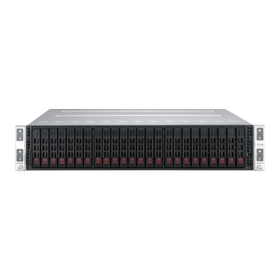
Chapter 1: Introduction 1.2 System Features The following views of the system display the main features. Refer to Appendix C for additional specifications. Front View Node A Node B Node C Node D Figure 1-1. Front View Logical Storage Drive Numbers Item Description 0 - 5... -
Page 12: Control Panel
Chapter 1: Introduction Control Panel Power Button NIC LED Information LED UID Button/LED BMC Reset Figure 1-2. Control Panel Control Panel Features Feature Description The main power switch applies or removes primary power from the power supply to the Power Button associated node but maintains standby power. -
Page 13: Rear View
Chapter 1: Introduction Rear View Two SFP + 10GbE Ports PWS1 Two USB 3.0 Ports PWS2 BMC LAN UID LED/BMC Reset Two SFP + 10GbE Ports PWS1 PWS2 Two USB 3.0 Ports BMC LAN UID LED/BMC Reset Figure 1-3. System: Rear View (SYS-211TP-HPTR top, SYS-211TP-HPTRD bottom) System Features: Rear (per Node) Feature Description... -
Page 14: Power Supply Indicator
Indicates that the power supply has a warning condition and continues to operate. Indicates that the power supply is plugged in, and is in an abnormal state. The Solid Amber system might need service. Please contact Supermicro technical support. No AC power to modules Expansion Slots and Riser Cards This system offers options for riser cards that provide custom PCIe 5.0 capabilities. -
Page 15: Top View: Node
Chapter 1: Introduction Top View: Node Storage Adapter Two M.2 NVMe (2280/22110) Single Intel® Xeon® Scalable Processor PCIe 5.0 x16 Riser Card Eight DDR5 DIMM Slots PCIe 5.0 x16 Riser Card Dual SFP+ 10G Ports BMC Password Sticker Figure 1-4. Node: Top View, SYS-211TP-HPTR/HPTRD BMC Password Each node has a unique password for ADMIN user access to the BMC. -
Page 16: System Architecture
Chapter 1: Introduction 1.3 System Architecture This section shows the locations of the main components of a node. Main Components: Node Storage Adapter Motherboard M.2-NVMe Adapter Eight DIMM Slots Processor Add-on Card Add-on Card Riser Card 2 Riser Card 1 Figure 1-5. -
Page 17: Main Components: System Backplane
Chapter 1: Introduction Main Components: System Backplane Storage Backplane Figure 1-6. Backplane Location... -
Page 18: Motherboard Layout
Chapter 1: Introduction 1.4 Motherboard Layout Below is a layout of the X13SET-PT motherboard with jumper, connector and LED locations shown. See the table on the following page for descriptions. For detailed descriptions, pinout information and jumper settings, refer to Chapter 4 or the Motherboard... -
Page 19: Quick Reference Table
Intel PCH Powered SATA 3.0 Ports with support for SuperDOM (Disk on Module) devices SXB1 Six SATA connections (SATA0–5) supported by PCH SXB3 PCIe 5.0 x16 Slot supported by CPU for the Supermicro proprietary riser card Note: The table is continued on next page. - Page 20 Chapter 1: Introduction SXB4 PCIe 5.0 x16 Slot supported by CPU for the Supermicro proprietary riser card USB0, USB1 Rear I/O USB Ports (USB 3.2 Gen 1) Rear VGA Port on the I/O back panel Note 1: For details on how to configure Network Interface Card (NIC) settings, refer to the Network Interface Card Configuration User's Guide posted on our website under the link: http://www.supermicro.com/support/manuals/.
-
Page 21: Motherboard Block Diagram
Chapter 1: Introduction Motherboard Block Diagram Note: DIMM Layout Impleme CPU 1 CPU 1 PE0[0–15] PE2[0–15] PE1[8–15] PE3[4–7] PE3[0–3] Up to 4800 MT/s Up to 4800 MT/s PCIe 5.0 x16 PCIe 5.0 x4 GENZ SXB4 1ST M.2 PCIe 5.0 x16 PCIe 5.0 x4 2ND M.2 SXB3... -
Page 22: Chapter 2 Server Installation
Chapter 2: Server Installation Chapter 2 Server Installation 2.1 Overview This chapter provides advice and instructions for mounting your system in a server rack. If your system is not already fully integrated with processors, system memory etc., refer to Chapter 3 for details on installing those specific components. -
Page 23: Rack Precautions
Chapter 2: Server Installation • This product is not suitable for use with visual display workplace devices according to §2 of the German Ordinance for Work with Visual Display Units. Rack Precautions • Ensure that the leveling jacks on the bottom of the rack are extended to the floor so that the full weight of the rack rests on them. -
Page 24: Airflow
Chapter 2: Server Installation Airflow Equipment should be mounted into a rack so that the amount of airflow required for safe operation is not compromised. Mechanical Loading Equipment should be mounted into a rack so that a hazardous condition does not arise due to uneven mechanical loading. -
Page 25: Installing The Rails
Chapter 2: Server Installation 2.4 Installing the Rails There are a variety of rack units on the market, which may require a slightly different assembly procedure. This rail set fits a rack between 26.8" and 36.4" deep. The following is a basic guideline for installing the system into a rack with the rack mounting hardware provided. -
Page 26: Releasing The Inner Rail
Chapter 2: Server Installation Releasing the Inner Rail Each inner rail has a locking latch. This latch prevents the server from coming completely out of the rack when when the chassis is pulled out for servicing. To mount the rail onto the chassis, first release the inner rail from the outer rails. 1. -
Page 27: Installing The Inner Rails On The Chassis
Chapter 2: Server Installation Installing the Inner Rails on the Chassis Installing the Inner Rails 1. Identify the left and right inner rails. They are labeled. 2. Place the inner rail firmly against the side of the chassis, aligning the hooks on the side of the chassis with the holes in the inner rail. -
Page 28: Installing The Outer Rails Onto The Rack
Chapter 2: Server Installation Installing the Outer Rails onto the Rack Each end of the assembled outer rail includes a bracket with hooks and square, spring-loaded pegs to fit into the square holes in your rack. Installing the Outer Rail 1. -
Page 29: Installing The Chassis Into A Rack
Chapter 2: Server Installation 2.5 Installing the Chassis into a Rack Once rails are attached to the chassis and the rack, you can install the server. Warning: Mounting the system into the rack requires at least two people to support the chassis during installation. -
Page 30: Removing The Chassis From The Rack
Chapter 2: Server Installation Removing the Chassis from the Rack Caution! It is dangerous for a single person to off-load the heavy chassis from the rack without assistance. Be sure to have sufficient assistance supporting the chassis when removing it from the rack. -
Page 31: Chapter 3 Maintenance And Component Installation
Chapter 3: Maintenance and Component Installation Chapter 3 Maintenance and Component Installation This chapter provides instructions on installing and replacing main system components. To prevent compatibility issues, only use components that match the specifications and/or part numbers given. Installation or replacement of most components require that power first be removed from the system. -
Page 32: Accessing The System
Chapter 3: Maintenance and Component Installation 3.2 Accessing the System Removing a Node Compute nodes can be removed while the other nodes continue operating. Power down the node, remove the cables, then pull the node out using the handles Figure 3-1. Removing the Compute Node... -
Page 33: Removing The Top Cover
Chapter 3: Maintenance and Component Installation Removing the Top Cover The system features a removable top cover, which allows access to the inside of the system. • Remove the two top screws and lift the top cover up. Check that all ventilation openings on the top cover and the top of the system are clear and unobstructed. -
Page 34: Processor And Heatsink Installation
• Installing the PHM to the motherboard socket requires a Torx T30 screwdriver. • Refer to the Supermicro website for updates on processor support. • All graphics in this manual are for illustration purposes only. Your components may look different. -
Page 35: Installation Overview
Chapter 3: Maintenance and Component Installation Installation Overview Four steps to install the processor and heatsink onto the motherboard. 1. Attach the processor to a plastic carrier to create the processor carrier assembly. 2. Attach the processor carrier assembly to the heatsink to create the processor heatsink module (PHM). -
Page 36: Create The Processor Carrier Assembly
Chapter 3: Maintenance and Component Installation Create the Processor Carrier Assembly Processor Carrier Assembly 1. Hold the processor with the gold pins (LGA lands) facing down. Locate the gold triangle at the corner of the processor and the corresponding hollowed triangle on the processor carrier as shown below. - Page 37 Chapter 3: Maintenance and Component Installation 2. Turn the processor over with the gold pins up. Locate the CPU keys on the processor and the four latches on the carrier as shown below. SP XCC Latch CPU Key Latch CPU Key Latch Latch SP MCC...
- Page 38 Chapter 3: Maintenance and Component Installation 3. Locate the lever on the CPU socket and press it down as shown below. Lever Lever Carrier E1B Carrier E1A 4. Using Pin 1 as a guide, carefully align the CPU keys (A and B) on the processor against the CPU keys on the carrier (a and b).
- Page 39 Chapter 3: Maintenance and Component Installation 6. After the processor is placed inside the carrier, examine the four sides of the processor, making sure that the processor is properly seated on the carrier. SP XCC (Top View) (Component View) CPU Carrier Assembly SP MCC (Component View) (Top View)
-
Page 40: Creating The Phm
Chapter 3: Maintenance and Component Installation Creating the PHM After creating the processor carrier assembly, follow the instructions below to mount the processor carrier into the heatsink to form the PHM. Note: If this is a new heatsink, the thermal grease has been pre-applied on the underside. Otherwise, apply the proper amount of thermal grease. - Page 41 Chapter 3: Maintenance and Component Installation CPU Carrier Assembly (CPU Component Side and Heatsink Bottom Side) SP XCC SP MCC Pin 1 Pin 1 Processor Heatsink Module (PHM)
-
Page 42: Preparing The Cpu Socket For Installation
Chapter 3: Maintenance and Component Installation Preparing the CPU Socket for Installation This motherboard comes with a plastic protective cover installed on the CPU socket. Remove it from the socket by following the instructions below: 1. Press the tabs inward. 2. -
Page 43: Installing The Phm Into The Cpu Socket
Chapter 3: Maintenance and Component Installation Installing the PHM into the CPU Socket 1. Locate four threaded fasteners on the CPU socket. 2. Follow the illustration to align PEEK nuts A, B, C, and D of the heatsink with threaded fasteners a, b, c, and d on the CPU socket. -
Page 44: Removing The Phm From The Cpu Socket
Chapter 3: Maintenance and Component Installation Removing the PHM from the CPU Socket Before removing the PHM from the motherboard, be sure to shut down the system and unplug the power cables from the power supply. Then follow the steps below: 1. -
Page 45: Removing The Processor Carrier Assembly From The Phm
Chapter 3: Maintenance and Component Installation Removing the Processor Carrier Assembly from the PHM To remove the processor carrier assembly from the PHM, please follow the steps below: 1. Detach the four plastic clips (marked a, b, c, d) on the processor carrier assembly from the four corners of the heatsink (marked A, B, C, D) as shown in the drawings below. -
Page 46: Removing The Processor From The Processor Carrier Assembly
Chapter 3: Maintenance and Component Installation Removing the Processor from the Processor Carrier Assembly Once you have removed the processor carrier assembly from the PHM, you are ready to remove the processor from the processor carrier by following the steps below. 1. -
Page 47: Memory
Chapter 3: Maintenance and Component Installation 3.4 Memory Note: Check the Supermicro website for recommended memory modules. Important: Exercise extreme care when installing or removing DIMM modules to prevent any possible damage. Memory Support The X13SET-PT motherboard supports up to 2 TB of ECC RDIMM/RDIMM 3DS DDR5 memory with speeds of 4800 MT/s in eight memory slots. - Page 48 Chapter 3: Maintenance and Component Installation DDR5 Memory Support for the 4th Generation Intel Xeon Scalable Processors-SP Speed (MT/s) DIMM Capacity (GB) One DIMM per Two DIMMs per Ranks Per DIMM Channel Channel Type and Data Width (Stack) Memory Memory Density Density 1.1 Volts...
-
Page 49: General Guidelines For Optimizing Memory Performance
Chapter 3: Maintenance and Component Installation General Guidelines for Optimizing Memory Performance • It is recommended to use DDR5 memory of the same type, size, and speed. • Mixed DIMM speeds can be installed. However, all DIMMs will run at the speed of the slowest DIMM. -
Page 50: Dimm Installation
Chapter 3: Maintenance and Component Installation DIMM Installation UID-SW JUIDB1 UID_LED1 BMC_LAN PRESS FIT JSTBY1 JSTBY1: 5 V STBY POWER 1. Insert the desired number of DIMMs JIPMB1 FAN3 SXB3 LAN2 LAN1 into the memory slots based on the X710 Recommended Memory Population Guide JNCSI1 tables on... -
Page 51: Motherboard Battery
Chapter 3: Maintenance and Component Installation 3.5 Motherboard Battery The motherboard uses non-volatile memory to retain system information when system power is removed. This memory is powered by a lithium battery residing on the motherboard. Replacing the Battery Begin by removing power from the system. -
Page 52: Storage Drives
The system supports 24 hot-swap 2.5" hybrid storage drive bays, six per node. The drives are mounted in drive carriers that simplify their removal from the chassis. These carriers also help promote proper airflow. Note: Enterprise level drives are recommended for use in Supermicro servers. For compatible drives, see the X13SET-PT motherboard page. - Page 53 Chapter 3: Maintenance and Component Installation Figure 3-6. Removing Drives...
-
Page 54: Mounting A Drive In A Drive Carrier
Chapter 3: Maintenance and Component Installation Mounting a Drive in a Drive Carrier 1. To add a new drive, install it into the carrier with the printed circuit board side facing down so that the mounting holes align with those in the carrier. 2. -
Page 55: Drive Carrier Indicators
Chapter 3: Maintenance and Component Installation Drive Carrier Indicators Each drive carrier has two LED indicators: an activity indicator and a status indicator. For RAID configurations using a controller, the meaning of the status indicator is described in the table below. -
Page 56: System Cooling
Chapter 3: Maintenance and Component Installation 3.7 System Cooling Fans The chassis contains four 8-cm high-performance fans. Fan speed is controlled by the BMC depending on the system temperature. If a fan fails, the remaining fans will ramp up to full speed. - Page 57 5. Push the fan up from the bottom and out of the top of the housing. 6. Replace the failed fan with an identical fan, available from Supermicro. Push the new fan into the housing, making sure the air flow direction is the same.
-
Page 58: Air Shrouds
Chapter 3: Maintenance and Component Installation Air Shrouds Air shrouds concentrate airflow to maximize cooling efficiency. Installing the Standard Air Shrouds 1. Screw the guide pins into the sled as shown below. 2. Position the air shrouds and drop them onto the guide pins and into place. Figure 3-14. -
Page 59: Power Supply
• Solid Amber: When illuminated, indicates that the power supply is plugged in, and is in an abnormal state. The system might need service. Please contact Supermicro technical support. Changing the Power Supply Module 1. Unplug the power cord from the module to be replaced. - Page 60 Chapter 3: Maintenance and Component Installation PWS1 Release Tab PWS2 Figure 3-15. System Power Supply (SYS-211TP-HPTR) PWS1 Release Tab PWS2 Figure 3-16. System Power Supply (SYS-211TP-HPTRD) 2000W -48V DC Input Power Supply Cable Connection Information Guide Power Supply Part Number: PWS-2K03D-1R Input Cable Part Number: CBL-PWEX-1058 Power...
-
Page 61: Pci Expansion Slots
Chapter 3: Maintenance and Component Installation 3.9 PCI Expansion Slots Each node offers options for riser cards that provide custom PCIe capabilities—one right- facing WIO riser card, and one left-facing WIO card. Figure 3-17. Expansion Card Chassis Slots Expansion Slots and Riser Cards This system offers options for riser cards that provide custom PCIe 5.0 capabilities. - Page 62 Chapter 3: Maintenance and Component Installation Riser Card Bracket Riser Card PCI Slot Shield Figure 3-18. Installing an Expansion Card...
-
Page 63: Chapter 4 Motherboard Connections
Chapter 4: Motherboard Connections Chapter 4 Motherboard Connections This section describes the connections on the motherboard and provides pinout definitions. Note that depending on how the system is configured, not all connections are required. The LEDs on the motherboard are also described here. A motherboard layout indicating component locations may be found in Chapter 1. -
Page 64: Headers And Connectors
Chapter 4: Motherboard Connections 4.2 Headers and Connectors 4-pin BMC External I2C Header A System Management Bus header for BMC is located at JIPMB1. Connect the appropriate cable here to use the IPMB I2C connection on your system. Refer to the table below for pin definitions. - Page 65 These SATA ports are supported by the Intel® C741 chipset. SATA6 and SATA7 can be used with Supermicro SuperDOMs, which are orange SATA DOM connectors with power pins built in and do not require external power cables. SATA0–5 are supported by PCH and are connected to Supermicro storage backplane.
- Page 66 The JTPM1 connector is used to connect a Trusted Platform Module (TPM)/Port 80, which is available from Supermicro (optional). A TPM/Port 80 connector is a security device that supports encryption and authentication in hard drives. It allows the motherboard to deny access if the TPM associated with the hard drive is not installed in the system.
-
Page 67: Input/Output Ports
Chapter 4: Motherboard Connections 4.3 Input/Output Ports See the figure below for the locations and descriptions of the I/O ports on the rear of the motherboard. Rear I/O Ports Description Description Description LED1 LED2 UID Switch / BMC Reset Button LAN1 USB0 (3.2 Gen 1) VGA Port... - Page 68 Chapter 4: Motherboard Connections COM Port Header One COM (communication) port header (COM1) that supports serial link interface is on this motherboard. COM1 is located next to VGA port. VGA Connection There is one VGA connection in your system. The VGA port is located on the rear I/O panel. The VGA connection provides analog interface support between the computer and the video displays.
- Page 69 BMC on the motherboard. For more details on the UID LEDs and BMC LEDs, refer to the tables below. Also, refer to the BMC User's Guide posted on our website at www. supermicro.com for more information on BMC. UID/BMC Reset Switch (JUIDB1)
- Page 70 Chapter 4: Motherboard Connections Universal Serial Bus (USB) Ports Two USB ports (USB0/1, USB 3.2 Gen 1) located on the rear I/O panel. The USB ports can be used for USB support via USB cables (not included). Back Panel USB0/1 (USB 3.2 Gen 1) Pin Definitions Pin# Definition...
-
Page 71: Jumpers
Chapter 4: Motherboard Connections 4.4 Jumpers How Jumpers Work To modify the operation of the motherboard, jumpers can be used to choose between optional settings. Jumpers create shorts between two pins to change the function of the connector. Pin 1 is identified with a square solder pad on the printed circuit board. See the diagram below for an example of jumping pins 1 and 2. - Page 72 Chapter 4: Motherboard Connections LAN Port Enable/Disable JPTG1 allows you to enable/disable the onboard LAN ports. The default setting is pins 1-2 to enable the connection. Refer to the table below for jumper settings. LAN Enable/Disable Jumper Settings Jumper Setting Definition Pins 1-2 Enabled...
-
Page 73: Led Indicators
Chapter 4: Motherboard Connections 4.5 LED Indicators BMC Heartbeat LED LEDM1 is the BMC heartbeat LED. When the LED is blinking green, BMC is functioning normally. Refer to the table below for the LED status. BMC Heartbeat LED Indicator LED Color Definition Blinking Green BMC Normal... - Page 74 Chapter 4: Motherboard Connections SFP+ LAN Link/Activity LEDs Two SFP+ LAN Link/Activity LED indicators (LED1 for LAN1, LED2 for LAN2) are located on the rear I/O panel of the motherboard. Each SFP+ LAN port has two LEDs. The green LED indicates activity, while the other Link LED may be green, yellow, or off to indicate the speed of the connection.
-
Page 75: Chapter 5 Software
1. Create a method to access the MS Windows installation ISO file. That can be a USB flash or media drive, or the BMC KVM console. 2. Retrieve the proper RST/RSTe driver. Go to the Supermicro web page for your motherboard and click on "Download the Latest Drivers and Utilities", select the proper driver, and copy it to a USB flash drive. - Page 76 Chapter 5: Software 4. During Windows Setup, continue to the dialog where you select the drives on which to install Windows. If the disk you want to use is not listed, click on “Load driver” link at the bottom left corner. To load the driver, browse the USB flash drive for the proper driver files.
-
Page 77: Driver Installation
The Supermicro website contains drivers and utilities for your system at https://www. supermicro.com/wdl/driver. Some of these must be installed, such as the chipset driver. After accessing the website, go into the CDR_Images (in the parent directory of the above link) and locate the ISO file for your motherboard. Download this file to a USB flash drive or media drive. -
Page 78: Superdoctor ® 5
5.3 SuperDoctor ® The Supermicro SuperDoctor 5 is a program that functions in a command-line or web-based interface for Windows and Linux operating systems. The program monitors such system health information as CPU temperature, system voltages, system power consumption, fan speed, and provides alerts via email or Simple Network Management Protocol (SNMP). -
Page 79: Bmc
Figure 5-3. BMC Password Label When logging in to the BMC for the first time, use the unique password provided by Supermicro to log in. You can change the unique password to a user name and password of your choice for subsequent logins. -
Page 80: Chapter 6 Optional Components
It enables the motherboard to deny access if the TPM associated with the hard drive is not installed in the system. Details and installation procedures are at: http://www.supermicro.com/manuals/other/TPM.pdf. • AOM-TPM-9670H •... -
Page 81: Enabling Intel Sgx In The Uefi Bios Setup Utility
Chapter 6: Optional Components 6.3 Enabling Intel SGX in the UEFI BIOS Setup Utility This section provides instructions to enable Intel Software Guide Extensions support on the UEFI BIOS. Requirements To ensure that Intel SGX is supported by your system, be sure to meet the following requirements: •... -
Page 82: Processor Requirements
• A standalone Intel SGX PSW for Windows OS is also available. (Please refer to Intel's website.) Note: Depending on Windows version, PSW and drivers may already be automatically installed. Supermicro Platform Support • Supermicro systems based on X13SET-PT motherboard. -
Page 83: Step 1: Entering The Uefi Bios Utility To Enable Tme Support
Chapter 6: Optional Components Step 1: Entering the UEFI BIOS Utility to Enable TME Support To enable Intel SGX support on the BIOS setting, enter the BIOS Setup utility by following the instructions below: 1. Press <Del> during system boot to enter the BIOS Setup utility. 2. -
Page 84: Step 2: Disabling Mirror Mode, Adddc Sparing*, And Patrol Scrub Support In The Memory-Ras Configuration Submenu
Without required DRAMs present, this feature will not be activated but remains dormant, hidden from the user's view. For ADDDC memory support, refer to the Memory RAS Configuration User's Guide posted on our website at: https://www.supermicro.com/manuals/ other/Memory_RAS_Configuration_User_Guide.pdf. Note 2: If ADDDC Sparing does not appear on your BIOS screen, this feature is inactive and masked off by default, and you will not need to disable it manually. - Page 85 Chapter 6: Optional Components 6. Scroll down to check if the feature ADDDC Sparing displays on your screen. If ADDDC Sparing does not appear on your screen, this feature is not activated, and you do not need to disable it manually. If ADDDC Sparing is displayed on your screen, use the arrow keys to select it and press <Enter>.
-
Page 86: Step 3: Enabling Numa And Disabling Uma-Based Clustering Support In The Acpi Submenu
Chapter 6: Optional Components Step 3: Enabling NUMA and Disabling UMA-Based Clustering Support in the ACPI Submenu For Intel SGX to function properly, please enable NUMA (Non-Uniform Memory Access) and disable UMA-Based Clustering support in the ACPI submenu by following the instructions below. -
Page 87: Step 4: Enabling Sgx Support In The Cpu Configuration Settings
Chapter 6: Optional Components Step 4: Enabling SGX Support in the CPU Configuration Settings After configuring the memory-related features in the UEFI BIOS utility as instructed above, your system is ready to support Intel Software Guard Extensions. To use SGX, follow the instructions below. -
Page 88: Intel Virtual Raid On Cpu (Vroc)
Chapter 6: Optional Components 6.4 Intel Virtual RAID on CPU (VROC) Intel Virtual RAID on CPU (Intel VROC) is an enterprise RAID solution for NVMe SSDs ® directly attached to Intel Xeon Scalable processors. Intel Volume Management Device (VMD) is an integrated controller inside the CPU PCIe root complex. Strip sizes are 4K, 8K, 16K, 32K, 64K, 128K. -
Page 89: Additional Information
Chapter 6: Optional Components Additional Information Additional information is available on the product page for the Supermicro add-on card and the linked manuals. www.supermicro.com/products/accessories/addon/AOC-VROCxxxMOD.cfm Hardware Key The Intel VROC hardware key is a license key that detects the Intel VROC SKU and activates the function accordingly. -
Page 90: Configuring Nvme Raid Manually
Chapter 6: Optional Components Configuring NVMe RAID Manually RAID for NVMe SSDs is enabled by default when Intel VROC Raid Key is populated. It may be managed manually through the UEFI BIOS. 1. Reboot the server and press [DEL] key to access the BIOS options. 2. - Page 91 Chapter 6: Optional Components Figure 6-3. BIOS, Manual Mode (Example—your server may look different.) 3. Select the desired PStack# to Enable or Disable the corresponding Intel VMD controller Figure 6-4. BIOS, Enabling VMD for Pstack0...
- Page 92 Chapter 6: Optional Components 4. Select the desired PCIe slot to Enable or Disable Intel VMD functionality according to the current hardware configuration being used. Hot Plug Capability can also be Enabled or Disabled. Figure 6-5. BIOS, Enabling VMD Functionality per Slot 5.
- Page 93 Chapter 6: Optional Components Figure 6-7. BIOS, Enabling CPU2 Example 6. Press [F4] to save the configuration and reboot the system and press [DEL] to enter BIOS. Note: Disabling the VMD controller without first deleting the associated existing RAID volume can lead to unexpected behavior. This action is strongly not recommended. Note: The effects of physically changing or swapping a CPU on the VMD controller enablement has not yet been thoroughly tested or documented.
-
Page 94: Related Information Links
Chapter 6: Optional Components 10. If cross-controller RAID is required, select Enable RAID spanned over VMD Controller. 11. Select specific disks for RAID with an [X]. Figure 6-8. Created Volume without Figure 6-9. Created Volume with enabling RAID spanned over VMD enabling RAID spanned over VMD controller controller... -
Page 95: Chapter 7 Troubleshooting And Support
Chapter 7 Troubleshooting and Support 7.1 Information Resources Website A great deal of information is available on the Supermicro website, supermicro.com. Figure 7-1. Supermicro Website • Specifications for servers and other hardware are available by clicking the Products option. •... -
Page 96: Bmc Interface
Security Center for recent security notices Supermicro Phone and Addresses 7.2 BMC Interface The system supports a Baseboard Management Controller (BMC) interface. It provides remote access, monitoring and management. There are several BIOS settings related to the BMC. -
Page 97: Troubleshooting Procedures
Chapter 7: Troubleshooting and Support 7.3 Troubleshooting Procedures Use the following procedures to troubleshoot your system. If you have followed all of the procedures below and still need assistance, refer to the ‘Technical Support Procedures’ and/ or ‘Returning Merchandise for Service’ section(s) in this chapter. Always disconnect the AC power cord before adding, changing or installing any non hot-swap hardware components. -
Page 98: System Boot Failure
Chapter 7: Troubleshooting and Support System Boot Failure If the system does not display Power-On-Self-Test (POST) or does not respond after the power is turned on, check the following: 1. Remove all components from the motherboard, especially the DIMM modules. 2. -
Page 99: When The System Becomes Unstable
Chapter 7: Troubleshooting and Support When the System Becomes Unstable A. If the system becomes unstable during or after OS installation, check the following: 1. CPU/BIOS support: Make sure that your CPU is supported and that you have the latest BIOS installed in your system. -
Page 100: Bios Post Codes
BIOS before downloading. Note: The SPI BIOS chip used on this motherboard cannot be removed. Send your motherboard back to our RMA Department at Supermicro for repair. For BIOS Recovery instructions, refer to the AMI BIOS Recovery Instructions posted at http://www.supermicro. - Page 101 Chapter 7: Troubleshooting and Support 4. The FLASH.NSH script will compare the Flash Descriptor Table (FDT) code in the new BIOS with the existing one in the motherboard: a. If a different FDT is found • A new file, STARTUP.NSH, will be created, and the system will automatically reboot in 10 seconds without you pressing any key.
-
Page 102: Battery Removal And Installation
Chapter 7: Troubleshooting and Support 7.6 Battery Removal and Installation Battery Removal To remove the onboard battery, follow the steps below: 1. Power off your system and unplug your power cable. 2. Locate the onboard battery as shown below. 3. Using a tool such as a pen or a small screwdriver, push the battery lock outwards to unlock it. -
Page 103: Where To Get Replacement Components
Before contacting Technical Support, take the following steps. Also, note that as a motherboard manufacturer, Supermicro also sells motherboards through its channels, so it is best to first check with your distributor or reseller for troubleshooting services. They should know of any possible problems with the specific system configuration that was sold to you. -
Page 104: Returning Merchandise For Service
For issues related to Red Hat Enterprise Linux, since it is a subscription based OS, contact your account representative. 7.10 Feedback Supermicro values your feedback as we strive to improve our customer experience in all facets of our business. To provide feedback on our manuals, please email us at techwriterteam@... -
Page 105: Contacting Supermicro
San Jose, CA 95131 U.S.A. Tel: +1 (408) 503-8000 Fax: +1 (408) 503-8008 Email: marketing@supermicro.com (General Information) Sales-USA@supermicro.com (Sales Inquiries) Government_Sales-USA@supermicro.com (Gov. Sales Inquiries) support@supermicro.com (Technical Support) RMA@supermicro.com (RMA Support) Webmaster@supermicro.com (Webmaster) Website: www.supermicro.com Europe Address: Super Micro Computer B.V. -
Page 106: Appendix A Standardized Warning Statements For Ac Systems
Supermicro's Technical Support department for assistance. Only certified technicians should attempt to install or configure components. Read this appendix in its entirety before installing or configuring components in the Supermicro chassis. These warnings may also be found on our website at http://www.supermicro.com/about/... - Page 107 Appendix A: Standardized Warning Statements Warnung WICHTIGE SICHERHEITSHINWEISE Dieses Warnsymbol bedeutet Gefahr. Sie befinden sich in einer Situation, die zu Verletzungen führen kann. Machen Sie sich vor der Arbeit mit Geräten mit den Gefahren elektrischer Schaltungen und den üblichen Verfahren zur Vorbeugung vor Unfällen vertraut. Suchen Sie mit der am Ende jeder Warnung angegebenen Anweisungsnummer nach der jeweiligen Übersetzung in den übersetzten Sicherheitshinweisen, die zusammen mit diesem Gerät ausgeliefert wurden.
- Page 108 Appendix A: Standardized Warning Statements . ٌ ا ك ً ف حالة و ٌ يك أى تتسبب ف اصابة جسذ ة ٌ هذا الزهز ع ٌ خطز !تحذ ز قبل أى تعول عىل أي هعذات،يك عىل علن بالوخاطز ال ا ٌجوة عي الذوائز ٍ...
- Page 109 Appendix A: Standardized Warning Statements Warnung Vor dem Anschließen des Systems an die Stromquelle die Installationsanweisungen lesen. ¡Advertencia! Lea las instrucciones de instalación antes de conectar el sistema a la red de alimentación. Attention Avant de brancher le système sur la source d'alimentation, consulter les directives d'installation. .יש...
- Page 110 Appendix A: Standardized Warning Statements Warnung Dieses Produkt ist darauf angewiesen, dass im Gebäude ein Kurzschluss- bzw. Überstromschutz installiert ist. Stellen Sie sicher, dass der Nennwert der Schutzvorrichtung nicht mehr als: 250 V, 20 A beträgt. ¡Advertencia! Este equipo utiliza el sistema de protección contra cortocircuitos (o sobrecorrientes) del edificio.
- Page 111 Appendix A: Standardized Warning Statements Power Disconnection Warning Warning! The system must be disconnected from all sources of power and the power cord removed from the power supply module(s) before accessing the chassis interior to install or remove system components (except for hot-swap components). 電源切断の警告...
- Page 112 Appendix A: Standardized Warning Statements אזהרה מפני ניתוק חשמלי !אזהרה יש לנתק את המערכת מכל מקורות החשמל ויש להסיר את כבל החשמלי מהספק .לפני גישה לחלק הפנימי של המארז לצורך התקנת או הסרת רכיבים يجب فصم اننظاو من جميع مصادر انطاقت وإ ز انت سهك انكهرباء من وحدة امداد انطاقت...
- Page 113 Appendix A: Standardized Warning Statements Attention Seul le personnel autorisé et le personnel de maintenance qualifié doivent être autorisés à installer, remplacer ou entretenir cet équipement.. !אזהרה .יש לאפשר רק צוות מורשה ואנשי שירות מוסמכים להתקין, להחליף או לטפל בציוד זה .ينبغي...
- Page 114 Appendix A: Standardized Warning Statements Warnung Diese Einheit ist zur Installation in Bereichen mit beschränktem Zutritt vorgesehen. Der Zutritt zu derartigen Bereichen ist nur mit einem Spezialwerkzeug, Schloss und Schlüssel oder einer sonstigen Sicherheitsvorkehrung möglich. ¡Advertencia! Esta unidad ha sido diseñada para instalación en áreas de acceso restringido. Sólo puede obtenerse acceso a una de estas áreas mediante la utilización de una herramienta especial, cerradura con llave u otro medio de seguridad.
- Page 115 Appendix A: Standardized Warning Statements Battery Handling Warning! There is the danger of explosion if the battery is replaced incorrectly. Replace the battery only with the same or equivalent type recommended by the manufacturer. Dispose of used batteries according to the manufacturer's instructions 電池の取り扱い...
- Page 116 Appendix A: Standardized Warning Statements هناك خطر من انفجار يف حالة اسحبذال البطارية بطريقة غري صحيحة فعليل اسحبذال البطارية فقط بنفس النىع أو ما يعادلها مام أوصث به الرشمة املصنعة جخلص من البطاريات املسحعملة وفقا لحعليامت الرشمة الصانعة 경고! 배터리가 올바르게 교체되지 않으면 폭발의 위험이 있습니다. 기존 배터리와 동일하거나 제 조사에서...
- Page 117 Appendix A: Standardized Warning Statements ¡Advertencia! Puede que esta unidad tenga más de una conexión para fuentes de alimentación. Para cortar por completo el suministro de energía, deben desconectarse todas las conexiones. Attention Cette unité peut avoir plus d'une connexion d'alimentation. Pour supprimer toute tension et tout courant électrique de l'unité, toutes les connexions d'alimentation doivent être débranchées.
- Page 118 Appendix A: Standardized Warning Statements Backplane Voltage Warning! Hazardous voltage or energy is present on the backplane when the system is operating. Use caution when servicing. バックプレーンの電圧 システムの稼働中は危険な電圧または電力が、 バックプレーン上にかかっています。 修理する際には注意く ださい。 警告 当系统正在进行时,背板上有很危险的电压或能量,进行维修时务必小心。 警告 當系統正在進行時,背板上有危險的電壓或能量,進行維修時務必小心。 Warnung Wenn das System in Betrieb ist, treten auf der Rückwandplatine gefährliche Spannungen oder Energien auf.
- Page 119 Appendix A: Standardized Warning Statements هناك خطز مه التيار الكهزبايئ أوالطاقة املىجىدة عىل اللىحة عندما يكىن النظام يعمل كه حذ ر ا عند خدمة هذا الجهاس 경고! 시스템이 동작 중일 때 후면판 (Backplane)에는 위험한 전압이나 에너지가 발생 합니다. 서비스 작업 시 주의하십시오. Waarschuwing Een gevaarlijke spanning of energie is aanwezig op de backplane wanneer het systeem in gebruik is.
- Page 120 Appendix A: Standardized Warning Statements תיאום חוקי החשמל הארצי !אזהרה .התקנת הציוד חייבת להיות תואמת לחוקי החשמל המקומיים והארציים تركيب املعدات الكهربائية يجب أن ميتثل للقىاويه املحلية والىطىية املتعلقة بالكهرباء 경고! 현 지역 및 국가의 전기 규정에 따라 장비를 설치해야 합니다. Waarschuwing Bij installatie van de apparatuur moet worden voldaan aan de lokale en nationale elektriciteitsvoorschriften.
- Page 121 Appendix A: Standardized Warning Statements Attention La mise au rebut ou le recyclage de ce produit sont généralement soumis à des lois et/ou directives de respect de l'environnement. Renseignez-vous auprès de l'organisme compétent. סילוק המוצר !אזהרה .סילוק סופי של מוצר זה חייב להיות בהתאם להנחיות וחוקי המדינה التخلص...
- Page 122 Appendix A: Standardized Warning Statements Warnung Gefährlich Bewegende Teile. Von den bewegenden Lüfterblätter fern halten. Die Lüfter drehen sich u. U. noch, wenn die Lüfterbaugruppe aus dem Chassis genommen wird. Halten Sie Finger, Schraubendreher und andere Gegenstände von den Öffnungen des Lüftergehäuses entfernt.
- Page 123 Verbindungskabeln, Stromkabeln und/oder Adapater, die Ihre örtlichen Sicherheitsstandards einhalten. Der Gebrauch von anderen Kabeln und Adapter können Fehlfunktionen oder Feuer verursachen. Die Richtlinien untersagen das Nutzen von UL oder CAS zertifizierten Kabeln (mit UL/CSA gekennzeichnet), an Geräten oder Produkten die nicht mit Supermicro gekennzeichnet sind.
- Page 124 .قيرح وأ لطع يف ببستي دق ىرخأ تالوحمو تالباك يأ مادختسا .ميلسلا سباقلاو لصوملا مجح لبق نم ةدمتعملا تالباكلا مادختسا تادعملاو ةيئابرهكلا ةزهجألل ةمالسلا نوناق رظحيUL وأCSA ( ةمالع لمحت يتلاوUL/CSA) لبق نم ةددحملاو ةينعملا تاجتنملا ريغ ىرخأ تادعم يأ عمSupermicro.
- Page 125 사항을 준수하여 제공되거나 지정된 연결 혹은 구매 케이블, 전원 케이블 및 AC 어댑터를 사용하십시오. 다른 케이블이나 어댑터를 사용하면 오작동이나 화재가 발생할 수 있습니다. 전기 용품 안전법은 UL 또는 CSA 인증 케이블 (코드에 UL / CSA가 표시된 케이블)을 Supermicro 가 지정한 제품 이외의 전기 장치에 사용하는 것을 금지합니다. Stroomkabel en AC-Adapter...
- Page 126 Supermicro's Technical Support department for assistance. Only certified technicians should attempt to install or configure components. Read this appendix in its entirety before installing or configuring components in the Supermicro chassis. These warnings may also be found on our website at http://www.supermicro.com/about/...
- Page 127 Appendix B: Standardized Warning Statements Warnung WICHTIGE SICHERHEITSHINWEISE Dieses Warnsymbol bedeutet Gefahr. Sie befinden sich in einer Situation, die zu Verletzungen führen kann. Machen Sie sich vor der Arbeit mit Geräten mit den Gefahren elektrischer Schaltungen und den üblichen Verfahren zur Vorbeugung vor Unfällen vertraut. Suchen Sie mit der am Ende jeder Warnung angegebenen Anweisungsnummer nach der jeweiligen Übersetzung in den übersetzten Sicherheitshinweisen, die zusammen mit diesem Gerät ausgeliefert wurden.
- Page 128 Appendix B: Standardized Warning Statements . ٌ ا ك ً ف حالة و ٌ يك أى تتسبب ف اصابة جسذ ة ٌ هذا الزهز ع ٌ خطز !تحذ ز قبل أى تعول عىل أي هعذات،يك عىل علن بالوخاطز ال ا ٌجوة عي الذوائز ٍ...
- Page 129 Appendix B: Standardized Warning Statements Warnung Vor dem Anschließen des Systems an die Stromquelle die Installationsanweisungen lesen. ¡Advertencia! Lea las instrucciones de instalación antes de conectar el sistema a la red de alimentación. Attention Avant de brancher le système sur la source d'alimentation, consulter les directives d'installation. .יש...
- Page 130 Appendix B: Standardized Warning Statements Warnung Dieses Produkt ist darauf angewiesen, dass im Gebäude ein Kurzschluss- bzw. Überstromschutz installiert ist. Stellen Sie sicher, dass der Nennwert der Schutzvorrichtung nicht mehr als: 60VDC, 20A beträgt. ¡Advertencia! Este equipo utiliza el sistema de protección contra cortocircuitos (o sobrecorrientes) del edificio.
- Page 131 Appendix B: Standardized Warning Statements Power Disconnection Warning Warning! The system must be disconnected from all sources of power and the power cord removed from the power supply module(s) before accessing the chassis interior to install or remove system components (except for hot-swap components). 電源切断の警告...
- Page 132 Appendix B: Standardized Warning Statements يجب فصم اننظاو من جميع مصادر انطاقت وإ ز انت سهك انكهرباء من وحدة امداد انطاقت قبم انىصىل إىن امنناطق انداخهيت نههيكم نتثبيج أو إ ز انت مكىناث الجهاز 경고! 시스템에 부품들을 장착하거나 제거하기 위해서는 섀시 내부에 접근하기 전에 반드시 전원 공급장치로부터...
- Page 133 Appendix B: Standardized Warning Statements Attention Il est vivement recommandé de confier l'installation, le remplacement et la maintenance de ces équipements à des personnels qualifiés et expérimentés. !אזהרה .צוות מוסמך בלבד רשאי להתקין, להחליף את הציוד או לתת שירות עבור הציוד واملدربيه...
- Page 134 Appendix B: Standardized Warning Statements Warnung Diese Einheit ist zur Installation in Bereichen mit beschränktem Zutritt vorgesehen. Der Zutritt zu derartigen Bereichen ist nur mit einem Spezialwerkzeug, Schloss und Schlüssel oder einer sonstigen Sicherheitsvorkehrung möglich. ¡Advertencia! Esta unidad ha sido diseñada para instalación en áreas de acceso restringido. Sólo puede obtenerse acceso a una de estas áreas mediante la utilización de una herramienta especial, cerradura con llave u otro medio de seguridad.
- Page 135 Appendix B: Standardized Warning Statements Battery Handling Warning! There is the danger of explosion if the battery is replaced incorrectly. Replace the battery only with the same or equivalent type recommended by the manufacturer. Dispose of used batteries according to the manufacturer's instructions 電池の取り扱い...
- Page 136 Appendix B: Standardized Warning Statements هناك خطر من انفجار يف حالة اسحبذال البطارية بطريقة غري صحيحة فعليل اسحبذال البطارية فقط بنفس النىع أو ما يعادلها مام أوصث به الرشمة املصنعة جخلص من البطاريات املسحعملة وفقا لحعليامت الرشمة الصانعة 경고! 배터리가 올바르게 교체되지 않으면 폭발의 위험이 있습니다. 기존 배터리와 동일하거나 제 조사에서...
- Page 137 Appendix B: Standardized Warning Statements ¡Advertencia! Puede que esta unidad tenga más de una conexión para fuentes de alimentación. Para cortar por completo el suministro de energía, deben desconectarse todas las conexiones. Attention Cette unité peut avoir plus d'une connexion d'alimentation. Pour supprimer toute tension et tout courant électrique de l'unité, toutes les connexions d'alimentation doivent être débranchées.
- Page 138 Appendix B: Standardized Warning Statements Backplane Voltage Warning! Hazardous voltage or energy is present on the backplane when the system is operating. Use caution when servicing. バックプレーンの電圧 システムの稼働中は危険な電圧または電力が、 バックプレーン上にかかっています。 修理する際には注意く ださい。 警告 当系统正在进行时,背板上有很危险的电压或能量,进行维修时务必小心。 警告 當系統正在進行時,背板上有危險的電壓或能量,進行維修時務必小心。 Warnung Wenn das System in Betrieb ist, treten auf der Rückwandplatine gefährliche Spannungen oder Energien auf.
- Page 139 Appendix B: Standardized Warning Statements هناك خطز مه التيار الكهزبايئ أوالطاقة املىجىدة عىل اللىحة عندما يكىن النظام يعمل كه حذ ر ا عند خدمة هذا الجهاس 경고! 시스템이 동작 중일 때 후면판 (Backplane)에는 위험한 전압이나 에너지가 발생 합니다. 서비스 작업 시 주의하십시오. Waarschuwing Een gevaarlijke spanning of energie is aanwezig op de backplane wanneer het systeem in gebruik is.
- Page 140 Appendix B: Standardized Warning Statements תיאום חוקי החשמל הארצי !אזהרה .התקנת הציוד חייבת להיות תואמת לחוקי החשמל המקומיים והארציים تركيب املعدات الكهربائية يجب أن ميتثل للقىاويه املحلية والىطىية املتعلقة بالكهرباء 경고! 현 지역 및 국가의 전기 규정에 따라 장비를 설치해야 합니다. Waarschuwing Bij installatie van de apparatuur moet worden voldaan aan de lokale en nationale elektriciteitsvoorschriften.
- Page 141 Appendix B: Standardized Warning Statements Attention La mise au rebut ou le recyclage de ce produit sont généralement soumis à des lois et/ou directives de respect de l'environnement. Renseignez-vous auprès de l'organisme compétent. סילוק המוצר !אזהרה .סילוק סופי של מוצר זה חייב להיות בהתאם להנחיות וחוקי המדינה التخلص...
- Page 142 Appendix B: Standardized Warning Statements Warnung Gefährlich Bewegende Teile. Von den bewegenden Lüfterblätter fern halten. Die Lüfter drehen sich u. U. noch, wenn die Lüfterbaugruppe aus dem Chassis genommen wird. Halten Sie Finger, Schraubendreher und andere Gegenstände von den Öffnungen des Lüftergehäuses entfernt.
- Page 143 Appendix B: Standardized Warning Statements DC Power Supply Warning! When stranded wiring is required, use approved wiring terminations, such as closedloop or spade-type with upturned lugs. These terminations should be the appropriate size for the wires and should clamp both the insulation and conductor. 警告...
- Page 144 Appendix B: Standardized Warning Statements وأ ةقلغم ةقلح لثم ،اهيلع ةقفاوملا ءاهنإ كالسألا مادختساو ،لبسلا مهب تعطقت نيذلا كالسألا ابولطم نوكي امدنع بجيو كالسألل بسانملا مجحلا نوكي تاءاهنإلا هذهل يغبنيو .ةبولقم تاورعلا عم عونلا ةيقيقحلا اهئامسأب ءايشألا .لصومو لزعلا نم لك حبك 주의! 꼬인...
- Page 145 Appendix B: Standardized Warning Statements Warnung Vor Ausführung der folgenden Vorgänge ist sicherzustellen, daß die Gleichstromschaltung keinen Strom erhält. ¡Advertencia! Antes de proceder con los siguientes pasos, comprobar que la alimentación del circuito de corriente continua (CC) esté cortada (OFF). Attention Avant de pratiquer l'une quelconque des procédures ci-dessous, vérifier que le circuit en courant continu n'est plus sous tension.
- Page 146 Appendix B: Standardized Warning Statements Hazardous Voltage or Energy Present on DC Power Terminals Warning! Hazardous voltage or energy may be present on DC power terminals. Always replace cover when terminals are not in service. Be sure uninsulated conductors are not accessible when cover is in place.
- Page 147 Appendix B: Standardized Warning Statements امدنع امئاد ءاطغ لادبتسا .ةمصاعلا ةقاطلا تاطحم ىلع ةدوجوم نوكت ةقاطلا وأ ةرطخلا دهجلا دق ءاطغلا امدنع اهيلإ لوصولا نكمي ال لوزعم ريغ تالصوملا هيف كش ال امم .ةمدخلا يف تسيل تاطحملا .هناكم يف 주의! DC전원...
- Page 148 Appendix C: System Specifications Appendix C System Specifications Processors Single 4th Gen Intel Xeon Scalable processor, LGA 4677 in Socket E; up to 52 cores and a thermal design power (TDP) of up to 270 W Chipset Intel® C741 BIOS AMI BIOS ACPI 6.0 or later, PCI firmware 4.0 support, SPI dual/quad speed support, Real Time Clock (RTC) wake up, riser card auto detection support, and SMBIOS 3.0 or later...
- Page 149 Appendix C: System Specifications Power Supply SYS-211TP-HPTR Model: PWS-2K04A-1R, 2000 W dual redundant modules, 80Plus Titanium level AC Input 1000 W: 100-127 Vac / 50-60 Hz 1800 W: 200-220 Vac / 50-60 Hz 2000 W: 200-240 Vac / 50-60 Hz (for UL/cUL only) 1980 W: 220-230 Vac / 50-60 Hz 2000 W: 230-240 Vac / 50-60 Hz +12 V...
- Page 150 Appendix C: System Specifications Applied Directives, Standards EMC/EMI: 2014/30/EU (EMC Directive) CLASS A Electromagnetic Compatibility Regulations 2016 FCC Part 15 Subpart B ICES-003 VCCI-CISPR 32 AS/NZS CISPR 32 BS/EN55032 BS/EN55035 CISPR 32 BS/EN 61000-3-2 BS/EN 61000-3-3 BS/EN 61000-4-2 BS/EN 61000-4-3 BS/EN 61000-4-4 BS/EN 61000-4-5 BS/EN 61000-4-6...
Need help?
Do you have a question about the SuperServer SYS-211TP-HPTR and is the answer not in the manual?
Questions and answers