
Related Manuals for Ruijie RG-MAP852-SF-M


Summary of Contents for Ruijie RG-MAP852-SF-M
- Page 1 Ruijie RG-MAP852-SF-M Access Point Hardware Installation and Reference Guide Document Version: V1.2 Date: August 28, 2023 Copyright © 2023 Ruijie Networks...
- Page 2 Due to product version upgrades or other reasons, the content of this document will be updated from time to time. Ruijie Networks reserves the right to modify the content of the document without any notice or prompt.
-
Page 3: Preface
Preface Intended Audience This document is intended for: Network engineers Technical support and servicing engineers Network administrators Technical Support Ruijie Networks Website: https://www.ruijienetworks.com/ Technical Support Website: https://ruijienetworks.com/support Case Portal: https://caseportal.ruijienetworks.com Community: https://community.ruijienetworks.com Technical Support Email: service_rj@ruijienetworks.com Skype: service_rj@ruijienetworks.com Conventions Conversions... - Page 4 Double slashes at the beginning of a line of code indicate a comment line. Signs The signs used in this document are described as follows: Warning An alert that calls attention to important rules and information that if not understood or followed can result in data loss or equipment damage.
-
Page 5: Table Of Contents
Contents Preface ..............................I 1 Product Introduction ........................1 1.1 Product Overview ........................1 1.2 Product Appearance ........................ 1 1.3 Package Contents ........................6 1.4 Technical Specifications ......................7 1.4.1 Dimensions and Weight....................7 1.4.2 RF Specifications ......................8 1.4.3 Port Specifications ...................... 10 1.4.4 Power Supply and Consumption ................ - Page 6 2.2.2 Ventilation Requirements ..................16 2.2.3 Space Requirements ....................16 2.2.4 Temperature/Humidity Requirements ..............16 2.2.5 Cleanliness Requirements ..................17 2.2.6 Anti-interference Requirements ................18 2.3 Tools ............................18 3 Installation ............................20 3.1 Installation Procedure ......................20 3.2 Checking Before Installation ....................21 3.3 Precautions ..........................
- Page 7 4.1 Establishing the Configuration Environment ..............32 4.2 Powering on the AP ........................ 32 4.2.1 Checklist Before Power-on ..................32 4.2.2 Checking the Environment After Power-on ............. 32 5 Monitoring and Maintenance ......................33 5.1 Monitoring ..........................33 5.1.1 Indicators ........................33 5.1.2 CLI Commands ......................
- Page 8 7.1 Connectors and Media ......................36 7.2 Cabling Recommendations ....................38 7.3 Optical Modules and Specifications ..................43 7.4 Power Adapter Specifications ....................45...
-
Page 9: Product Introduction
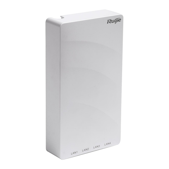
(ACs) to implement STA data forwarding, security, and access control. Product Appearance RG-MAP852-SF-M provides two RF ports, four Ethernet ports, one 2.5G SFP port, one micro USB console port, and one DC port. The following figures show the product appearance. - Page 10 Hardware Installation and Reference Guide Product Introduction Front View Figure 1-1...
- Page 11 Hardware Installation and Reference Guide Product Introduction Figure 1-1 Side View...
- Page 12 Hardware Installation and Reference Guide Product Introduction Figure 1-2 Rear View Table 1-1 Ports and Button on the Rear Side Item Description Power supply Phoenix terminal powered port for power supply of the port device SFP port Uplink service port for data transmission Used to reboot the device or restore the device to factory Reset button settings...
- Page 13 Hardware Installation and Reference Guide Product Introduction Figure 1-3 Bottom View Table 1-2 Port Description Port Description Used to show the running status of the system (The Indicator indicator is hidden and can be observed after the decorative cover is disassembled.) LAN 1 port Downlink service port for data transmission LAN 2 port...
-
Page 14: Package Contents
Hardware Installation and Reference Guide Product Introduction Figure 1-4 Right View Table 1-3 Port Description Port Description Connected with a serial port cable for device Console port management Package Contents Table 1-4 Package Contents Item Quantity RG-MAP852-SF-M Mounting bracket Mounting bracket latch... -
Page 15: Technical Specifications
Technical Specifications 1.4.1 Dimensions and Weight Table 1-5 Dimensions and Weight Dimensions and RG-MAP852-SF-M Weight Dimensions (W × D × 86 mm ×160 mm × 32.5 mm (3.39 in. x 6.30 in. x 1.28 in.) AP: 0.30 kg (0.70 lbs) Weight Mounting bracket: 0.05 kg (0.11 lbs) -
Page 16: Rf Specifications
Hardware Installation and Reference Guide Product Introduction Dimensions and RG-MAP852-SF-M Weight Mounting Hole 60 mm (2.36 in.) Pattern Mounting Hole 5.1 mm (0.20 in.) Diameter 1.4.2 RF Specifications Table 1-6 RF Specifications RF Specifications RG-MAP852-SF-M Bi-radio Up to four spatial streams Radio Design Radio 1: 2.4 GHz, 2 spatial streams: 2 ×... - Page 17 Hardware Installation and Reference Guide Product Introduction RF Specifications RG-MAP852-SF-M 2.4 GHz: 2.22 dBi Antenna Gain 5 GHz: 6.45 dBi 20 dBm Max. Transmit Note: The transmit power varies based on the regulations in Power different countries and regions. Transmit Power...
-
Page 18: Port Specifications
Hardware Installation and Reference Guide Product Introduction 1.4.3 Port Specifications Table 1-7 Port Specifications Ports RG-MAP852-SF-M Bluetooth Bluetooth 5.1 USB Port Not supported Uplink: 1 × 2.5G SFP port, incompatibility with 1G SFP port Fixed Service Ports Downlink: 4 × 10/100/1000Base-T adaptive Ethernet ports Fixed Management 1 ×... -
Page 19: Environment And Reliability
Hardware Installation and Reference Guide Product Introduction Power Supply RG-MAP852-SF-M Consumption Power Not supported Redundancy Caution To power the AP by using PoE, ensure that the device at the other end of the Ethernet cable supports IEEE 802.3af power supply. -
Page 20: Indicators And Buttons
Hardware Installation and Reference Guide Product Introduction Indicators and Buttons Note The LED description applies to both fit and fat modes unless otherwise specified. Table 1-9 System Indicator Status Frequen Indicator Status Description The AP is not powered on. The AP is powered on, but the indicator is manually turned off. - Page 21 Hardware Installation and Reference Guide Product Introduction Table 1-10 Reset Button Button Operation Result Press the button for less than 2s Reboot the device. Reset Press and hold the button for longer than Restore to factory button settings.
-
Page 22: Preparing For Installation
Hardware Installation and Reference Guide Preparing for Installation Preparing for Installation Safety Precautions Note To avoid personal injury and device damage, carefully read the safety precautions before you install the device. The following safety precautions may not cover all possible dangers. ... -
Page 23: Electric Safety
Hardware Installation and Reference Guide Preparing for Installation 2.1.3 Electric Safety Warning Improper or incorrect electric operations may cause a fire, electric shock, and other accidents, and lead to severe and fatal personal injury and device damage. Direct or indirect contact with high voltage or mains power supply via wet objects ... -
Page 24: Bearing Requirements
Hardware Installation and Reference Guide Preparing for Installation The installation site must meet the following requirements. 2.2.1 Bearing Requirements Evaluate the weight of the device and its accessories (such as the bracket and power supply module), and ensure that the ground of the installation site meets the requirements. -
Page 25: Cleanliness Requirements
Hardware Installation and Reference Guide Preparing for Installation 2.2.5 Cleanliness Requirements Dust poses a major threat to the running of the AP. The indoor dust falling on the AP may be adhered by static electricity, causing poor contact of the metallic joint. Such electrostatic adherence may occur more easily when the relative humidity is low, not only affecting the service life of the AP, but also causing communication faults. -
Page 26: Anti-Interference Requirements
Hardware Installation and Reference Guide Preparing for Installation Ammonia gas (NH3) 0.05 0.15 Chlorine gas (CI2) 0.01 Note Average refers to the average value of harmful gases measured in one week. Maximum refers to the upper limit of harmful gases measured in one week, and the maximum value cannot last for more than 30 minutes every day. - Page 27 Hardware Installation and Reference Guide Preparing for Installation Note RG-MAP852-SF-M is not delivered with a tool kit. You need to prepare a tool kit by yourself.
-
Page 28: Installation
Hardware Installation and Reference Guide Installation Installation It is required that RG-MAP852-SF-M be fixed indoors. Caution Before installing the device, make sure that you have carefully read the requirements described in Chapter 2. Installation Procedure The installation steps are shown in the following figure. -
Page 29: Checking Before Installation
Hardware Installation and Reference Guide Installation Checking Before Installation Carefully plan and arrange the installation location, networking mode, power supply, and cabling before installing the device. Confirm the following requirements before installation: The installation location provides sufficient space for heat dissipation. ... -
Page 30: Precautions
Hardware Installation and Reference Guide Installation Figure 3-2 Bracket Dimensions Precautions To ensure the normal operation and prolonged service life of the AP, observe the following safety precautions: Do not power on the device during installation. Place the device in a well-ventilated environment. ... -
Page 31: Installing The Device
Hardware Installation and Reference Guide Installation Cut off the power switch before cleaning the device. Do not wipe the device with a damp cloth. Do not wash the device with liquid. Do not open the enclosure when the device is working. ... - Page 32 Hardware Installation and Reference Guide Installation Figure 3-4 Installing the Mounting Bracket (3) Loosen the security screw and enable it. Figure 3-5 Enabling the Security Screw Loosen the screw (4) Remove the decorative cover.
- Page 33 Hardware Installation and Reference Guide Installation Figure 3-6 Removing the Decorative Cover (5) Insert the fiber into the optical module and coil the external optical cable around in the back cable trough of the device. Caution Do not remove the security label from the optical module before inserting the optical ...
- Page 34 Hardware Installation and Reference Guide Installation Figure 3-7 Connecting the Optical Fiber Insert the optical fiber connector into the optical module, and lead the external cable from this entrance to the fiber spool. Coil the external optical fiber and lead it out here. Coil the optical fiber in the trough through the gap.
- Page 35 Hardware Installation and Reference Guide Installation Figure 3-8 Installing the AP (7) Install the decorative cover to the AP and lead the optical cable and power cable from the semi-circular groove on the top of the decorative cover. Figure 3-9 Installing the Decorative Cover Lead the optical cable and power cable from the semi-circular groove...
- Page 36 Hardware Installation and Reference Guide Installation Caution When installing or moving the wireless AP, ensure that the power supply is cut off. Ensure that the screws are tightened. Ensure that the wireless AP installation position facilitates indicator status ...
-
Page 37: Removing The Ap
Hardware Installation and Reference Guide Installation 3.4.2 Removing the AP (1) Disassemble the decorative cover. Figure 3-11 Removing the Decorative Cover (2) Hold the AP in your hands and slide it sideways and away from the bracket in the SFP port direction. -
Page 38: Bundling Cables
Hardware Installation and Reference Guide Installation Figure 3-12 Disassembling the AP Bundling Cables 3.5.1 Precautions Bundle cables neatly to ensure aesthetics. Bend twisted pairs naturally or to a large radius close to the connector. Do not over tighten twisted pair bundle as it may reduce the cable life and ... -
Page 39: Installation Verification
Hardware Installation and Reference Guide Installation Installation Verification 3.6.1 Checking the AP Check whether the external power supply matches the AP. Ensure that the AP is securely installed and will not move or fall. 3.6.2 Checking Cable Connection Verify that the twisted pair cable matches the port. -
Page 40: Debugging
Hardware Installation and Reference Guide Debugging Debugging Establishing the Configuration Environment Use a power adapter or PoE to power the AP. When setting up the environment, pay attention to the following: Verify that the AP is properly connected to the power source. ... -
Page 41: Monitoring And Maintenance
If the AP works in fat mode, you can log in to the AP remotely for maintenance. If the AP works in fit mode, you can use an AC to centrally manage and maintain the Hardware Maintenance If the hardware is faulty, please contact Ruijie technical support. -
Page 42: Troubleshooting
Check whether the indicators are normal. Check whether cables are properly connected with ports. Contact Ruijie technical support to check whether hardware faults exist. Common Troubleshooting Procedures 6.2.1 Ethernet Port Is Not Working After the Ethernet Cable Is Plugged In Verify that the device at the other end of the Ethernet cable is working properly. -
Page 43: Led Is Steady Red
Hardware Installation and Reference Guide Troubleshooting 6.2.3 LED Is Steady Red The LED keeps steady red for a long time, indicating that the Ethernet port is not connected. Verify the Ethernet connection. 6.2.4 LED Is Steady Green The device performs initialization after power-on. During this period, the LED keeps steady green and does not turn normal blue until the initialization is completed. -
Page 44: Appendix
Hardware Installation and Reference Guide Appendix Appendix Connectors and Media 1000BASE-T/100BASE-TX/10BASE-T port The 1000BASE-T/100BASE-TX/10BASE-T port is a 10/100/1000 Mbps auto-sensing port that supports auto MDI/MDIX Crossover. Compliant with IEEE 802.3ab, the 1000BASE-T port requires 100-ohm Category 5/5e UTP or STP with a maximum distance of 100 meters. The 1000BASE-T port requires all four pairs of wires be connected for data transmission. - Page 45 Hardware Installation and Reference Guide Appendix Table 7-2 100BASE-TX/10BASE-T Pin Assignments Socket Plug Input Receive Data+ Output Transmit Data+ Input Receive Data- Output Transmit Data- Output Transmit Data+ Input Receive Data+ Output Transmit Data- Input Receive Data- 4, 5, 7, 8 Not Used Not Used The following figure shows wiring of straight-through and crossover cables for...
-
Page 46: Cabling Recommendations
Hardware Installation and Reference Guide Appendix Cabling Recommendations During installation, route cable bundles upward or downward along the sides of the rack depending on the actual situation in the equipment room. All cable connectors should be placed at the bottom of the cabinet rather than be exposed outside of the cabinet. Power cords are routed beside the cabinet, and top cabling or bottom cabling is adopted according to the actual situation in the equipment room, such as the positions of the DC power distribution box, AC socket, or lightning protection box. - Page 47 Hardware Installation and Reference Guide Appendix Figure 7-1 Bundling Cables Twisting Bending Cables of different types (such as power cables, signal cables, and ground cables) ○ should be separated in cabling and bundling. Mixed bundling is not allowed. When they are close to each other, it is recommended that crossover cabling be adopted. In the case of parallel cabling, maintain a minimum distance of 30 mm between power cords and signal cables.
- Page 48 Hardware Installation and Reference Guide Appendix Figure 7-2 Cutting off Excess Cable Tie When cables need to be bent, bind them first but do not tie cable ties within the ○ bend. Otherwise, stress may be generated on the cables and cause the wires inside to break, as shown in Figure 7-3.
- Page 49 Hardware Installation and Reference Guide Appendix part should not touch heat sources, sharp corners, or sharp edges. If heat sources cannot be avoided, high-temperature cables should be used. When screw threads are used to fasten cable terminals, the bolt or screw must be ○...
- Page 50 Hardware Installation and Reference Guide Appendix No knot is allowed in cabling or bundling. ○ For wiring terminal blocks (such as circuit breakers) with cord end terminals, the ○ metal part of the cord end terminal should not be exposed outside the terminal block when assembled.
-
Page 51: Optical Modules And Specifications
Hardware Installation and Reference Guide Appendix Optical Modules and Specifications We provide appropriate optical modules according to the port types. You can select the module to suit your specific needs. The optical module types and corresponding specifications are provided for reference. Table 7-4 SFP Modules and Specifications Intensity of... - Page 52 Hardware Installation and Reference Guide Appendix Rate/Distance Pairing Model TSB-3GM3-53DCR (1550/1310) Caution The BIDI optical modules at both ends must be paired for use. For example, if TSB-3GM3-35DCR is used at one end, TSB-3GM3-53DCR must be used at the other end.
-
Page 53: Power Adapter Specifications
Hardware Installation and Reference Guide Appendix Power Adapter Specifications The AP uses a phoenix connector for power supply. Input voltage: 48 V DC; rated current: 0.5 A Table 7-7 DC Power Adapter Terminal Specifications Distance Terminal Insertion Between Polarity Width Depth Holes Reverse connection is supported.
Need help?
Do you have a question about the RG-MAP852-SF-M and is the answer not in the manual?
Questions and answers