Table of Contents
Advertisement
Quick Links
P4-30...R40-17
Model: C18a
Assembly and Operating Instructions
en
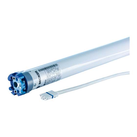
Tubular drive with integrated 915.3 MHz radio
receiver for ZIP systems
Important information for:
• Fitters / • Electricians / • Users
Please forward accordingly!
These instructions must be kept safe for future reference.
2010 301 078 0b 06/11/2018
Becker-Antriebe GmbH
Friedrich-Ebert-Straße 2-4
35764 Sinn/Germany
www.becker-antriebe.com
Advertisement
Table of Contents

Subscribe to Our Youtube Channel
Related Manuals for Becker P4-30


Summary of Contents for Becker P4-30
- Page 1 P4-30...R40-17 Model: C18a Assembly and Operating Instructions Tubular drive with integrated 915.3 MHz radio receiver for ZIP systems Important information for: • Fitters / • Electricians / • Users Please forward accordingly! These instructions must be kept safe for future reference.
-
Page 2: Table Of Contents
Table of contents General .................................... 3 Warranty ..................................... 4 Safety instructions ................................ 4 Instructions for the user.............................. 4 Instructions for installation and commissioning........................ 4 Intended use .................................. 6 Assembling and disassembling the plug-in connecting cable.................... 6 Assembling the plug-in connecting cable .......................... 6 Disassembling the plug-in connecting cable for tubular drives dia. -
Page 3: General
General These tubular drives are high-quality products with the following features: • Optimised for vertical ZIP applications • Individual, group and central radio control • No need to run wires to a switch or relay control device • Any combination of drive and transmitter possible •... -
Page 4: Warranty
Warranty Structural modifications and incorrect installation which are not in accordance with these and our other instructions can result in serious injuries, e.g., crushing of limbs. Therefore, structural modifications may only be carried out with our prior approval and strictly in accordance with our instructions, particularly the information contained in these Assembly and Operating Instructions. Any further processing of the products which does not comply with their intended use is not permitted. - Page 5 your safety and the safety of others. This means that the use of unapproved third-party products, or modifications which have not been agreed with or approved by us, are prohibited. We do not accept li- ability for damage or injury arising from such actions. •...
-
Page 6: Intended Use
Intended use The type of tubular drive described in these instructions is intended solely for the operation of vertical ZIP systems. It may only be used in networked systems if all the individual drives are exactly synchronised and reach their limit positions at the same time. -
Page 7: Disassembling The Plug-In Connecting Cable For Tubular Drives Dia. 35
Disassembling the plug-in connecting cable for tubular drives dia. 35. Caution Prior to disassembly, the power supply to the connecting cable must be disconnected. Insert a suitable flathead screwdriver between the locating lug and the snap-in pin, so that the snap-in pin releases the locating lug from the plug. -
Page 8: Disassembling The Plug-In Connecting Cable For Tubular Drives Dia. 45 And Dia. 58
Disassembling the plug-in connecting cable for tubular drives dia. 45 and dia. 58 Caution Prior to disassembly, the power supply to the connecting cable must be disconnected. Insert a suitable flathead screwdriver right into the recess of the locating latch, so that the latch releases the locating lug from the plug. -
Page 9: Undoing The Mounting Pin
Calculate the space required at the side (M) by measuring the drive head (1) and wall bracket (2). The clear dimension of the box (X) minus the space required at the side (M) and idler (G) gives the length (L) of the barrel: L=X-M-G. The space required at the side (M) varies depending on the combination of drive and wall bracket. -
Page 10: Assembling And Disassembling The Drive Adapter With Separate Drive Adapter Safety Catch
Assembling and disassembling the drive adapter with separate drive adapter safety catch Assembling and disassembling the drive adapter with screw connection Mounting the drive in the tube For profile tubes: In the case of some drive adapters, tolerances of the groove widths in different bar- rels can be offset by rotating the drive adapter into a different groove recess. - Page 11 Attention Do not hammer the tubular drive into the tube or drop it into the barrel! Assemble the tubular drive with the relevant ring (1) and drive adapter (2). If the ring has several grooves, select the groove which is a perfect fit and push the ring (1) onto the thrust ring.
-
Page 12: First Operation
First operation Explanation of symbols UP button STOP button DOWN button Programming button The tubular drive clicks to confirm (One or more times) The tubular drive shifts to confirm (One or more times) 1 = direction switch 2 = radio switch Attention The tubular drives are designed for short-time operation. -
Page 13: Programming The Master Transmitter
Readying the tubular drive for programming with the radio switch Switch the radio switch to the inside position. If the radio switch is already in this posi- tion, switch it to the outside and back to the inside position. ► The tubular drive is ready to programme for 3 minutes Programming the master transmitter Press the programming button for 3 seconds when it is ready to programme. -
Page 14: Intelligent Installation Management
Changing direction of rotation via master transmitter It is only possible to change the direction of rotation if no limit position has been set. Press the UP or DOWN button ▻ The shading solution runs in the desired direction. ► The running direction is OK. If the shading solution runs in the wrong direction, the running direction must be changed. -
Page 15: Deleting The Limit Positions
Lower point to upper stop Close to the desired lower limit position. Press the programming button and, within 3 seconds, also press the DOWN button and hold the two buttons down. ▻ The tubular drive acknowledges. Then open as far as the permanent stop. ▻... -
Page 16: Intermediate Positions I + Ii
Intermediate positions I + II The intermediate positions I + II are freely selectable positions for the shading solution between the two limit positions. Each travel button can be assigned one intermediate posi- tion. Both limit positions must be set before an intermediate position is set. Setting the desired intermediate position Open/close the shading solution to the desired intermediate position. -
Page 17: Deleting Transmitters
Deleting transmitters Deleting individual transmitters The programmed master transmitter cannot be deleted. It can only be overwritten (see Programming the master transmitter [} 13]). Press the programming button on the master transmitter for 3 seconds. ▻ The tubular drive acknowledges. Now press the programming button of the transmitter to be deleted for 3 seconds. ▻... -
Page 18: Setting The Limit Positions With Auto-Install (For Zip Applications With Heavy End Strip)
Switch off the tubular drive power for 5 seconds, then switch it back on. 230V AC / 50 Hz ▻ The tubular drive is ready to program for 3 minutes. 1 = blue 3 = black 2 = brown 4 = green/yellow Now press the programming button of the new master transmitter for 10 seconds. -
Page 19: Obstacle Detection (For Zip Applications With Heavy End Strip)
Obstacle detection (for ZIP applications with heavy end strip) Caution Obstacle detection is only active in conjunction with the "drive adapter for obstacle detec- tion". In addition, please note that the drive must be pushed in to the shaft as far as the band of the thrust ring. -
Page 20: Local Operation With A Single Button
Local operation with a single button Wiring Only use a single button (normally open). Connect one button for each drive. The button must not be operated during the first five seconds after the mains voltage has been switched on. Button (normally open) Button commands <... -
Page 21: Activating/Deactivating The Additional Fabric Untensioning Function With The Master Transmitter
This product is made of various materials which must be disposed of properly. Find out about the applicable regulations on recyc- ling or disposal for this product in your country. The packaging material must be disposed of properly. Maintenance These drives are maintenance-free. Technical data dia. 35 Tubular drive P4-30 P5-20 P8-16 Model C18a Type C PSOF Z1 A... -
Page 22: Technical Data Dia. 45
Technical data dia. 45 Tubular drive R8-17 R12-17 R20-17 R30-17 R40-17 Model C18a Type C PSOF Z1 A Rated torque [Nm] Output speed [rpm] Limit switch range 64 revolutions Supply voltage 240 V AC / 50 Hz Connected load [W] Rated current consumption [A] 0.45 0.50 0.70 0.95 1.10... -
Page 23: What To Do If
What to do if...? Problem Remedy Tubular drive is not functioning. Program new transmitter. Bring transmitter within range of the tubular drive. Press drive or stop button on transmitter at least 5 times in the immediate vicinity of the tubular drive. Insert batteries correctly or insert new batteries. -
Page 24: Sample Wiring Diagram
Sample wiring diagram...
Need help?
Do you have a question about the P4-30 and is the answer not in the manual?
Questions and answers