Table of Contents
Advertisement
Quick Links
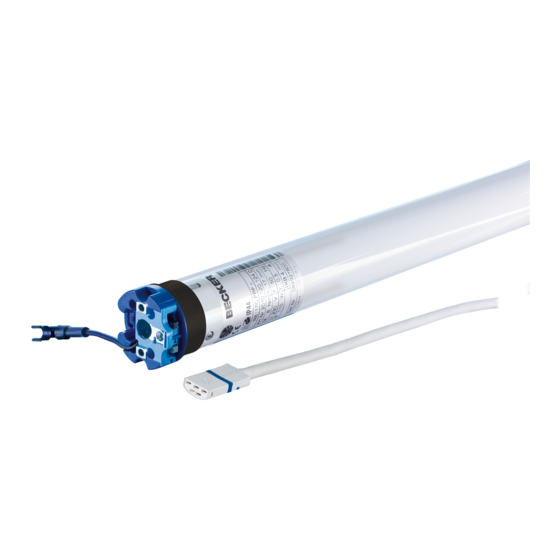
R12-17...L120-11
Model: M05
Assembly and Operating Instructions
en
Tubular drives with crank handle activation
Important information for:
• Fitters / • Electricians / • Users
Please forward accordingly!
These instructions must be kept safe for future reference.
2010 300 231 0i 12/09/2022
Becker-Antriebe GmbH
Friedrich-Ebert-Straße 2-4
35764 Sinn/Germany
www.becker-antriebe.com
Advertisement
Table of Contents

Related Manuals for Becker M05


Summary of Contents for Becker M05
- Page 1 R12-17...L120-11 Model: M05 Assembly and Operating Instructions Tubular drives with crank handle activation Important information for: • Fitters / • Electricians / • Users Please forward accordingly! These instructions must be kept safe for future reference. 2010 300 231 0i 12/09/2022 ...
-
Page 2: Table Of Contents
Table of contents General .................................... 3 Warranty ..................................... 3 Safety instructions ................................ 4 Instructions for the user.............................. 4 Instructions for installation and commissioning........................ 4 Intended use .................................. 5 Assembly .................................... 6 Setting the limit positions.............................. 9 Using the crank handle ............................... 10 Information for the electrician ............................. -
Page 3: General
General These tubular drives are high-quality products with the following features: • For use with roller shutters • For use with sunblinds • For use with doors • Convenient manual control in the event of power failure • Easy limit switch setting on the drive •... -
Page 4: Safety Instructions
Safety instructions The following safety instructions and warnings are intended to avert hazards and to prevent property damage and personal injury. Instructions for the user General information • The drive must be disconnected from its power source during cleaning and maintenance and when re- placing parts. -
Page 5: Intended Use
• If the drive is used for shading solutions in a specially marked area (e.g., escape routes, hazard zones, safety areas), compliance with all applicable regulations and standards must be ensured. • Once the drive has been installed, the fitter must mark the used tubular drive in the “Technical data” chapter and make a note of the installation position. -
Page 6: Assembly
Assembly Assembling the drive Attention To connect the drive to the driven part, solely mechanical accessory components made by the drive manufacturer from the current product catalogue may be used. Prior to mounting, the fitter must ensure that the masonry and the system being motorised are sufficiently robust (drive torque plus weight of the shading solution). - Page 7 Mounting the drive in the tube For profile shafts: In the case of some drive adapters, tolerances of the groove widths in different barrels can be offset by rotating the drive adapter into a different groove recess. These groove recesses have different sizes and allow the drive to fit exactly.
- Page 8 Mount the assembled unit comprising barrel, tubular drive and idler on the box as follows. 1. First insert the bearing pin into the idler (1.). 2. Then, mount the crank handle housing onto the respective fastening element using at least 2 M6 screws (2.).
-
Page 9: Setting The Limit Positions
Setting the limit positions The setting tool (Item no. 4933 300 019 0) can be used to set the limit positions. Setting tool Upper limit position Lower limit position Lower limit position Upper limit position Upper limit position Lower limit position Upper limit position Lower limit position Setting the lower limit position... -
Page 10: Using The Crank Handle
Using the crank handle For problem-free assembly, use mechanical and electrical accessories made by the drive manufacturer which have been tested and which are suitable for use with these drives. For 7 mm hexagonal tube The crank handle is to be used only in the event of a power failure. It must be ensured and 6 mm square tube that the limit positions are not overrun. -
Page 11: Technical Data Dia. 45
Technical data dia. 45 Tubular drive R12-17 R15-17 R20-17 R25-17 R30-17 R40-17 R50-11 Model Type Rated torque [Nm] Output speed [rpm] Limit switch range 38 revolutions Supply voltage 230 V AC / 50 Hz Connected load [W] Rated current consump- 0.50 0,65 0.75... -
Page 12: What To Do If
Tubular drive L70-17 L80-11 L80-17* L120-11 Model Type Rated torque [Nm] Output speed [rpm] Limit switch range 38 revolutions Supply voltage 230 V AC / 50 Hz Connected load [W] Rated current consumption [A] 1.90 1.40 2.10 1.90 Mode S2 4 min Degree of protection IP 44 Min. -
Page 13: Sample Wiring Diagrams
Sample wiring diagrams Operation via a switch/push-button Central, group and individual control using Centronic UnitControl UC42 Central Control unit Mains 230 V / 50 Hz Central cable 230 V / 50 Hz (connection to further control units) Group 230 V / 50 Hz Individual Individual 230 V / 50 Hz... -
Page 14: Declaration Of Conformity
Declaration of conformity For UK-Markets: The Declaration of Conformity can be provided upon request from Becker Motors Ltd., or can be downloaded on www.beckermo- tors.co.uk. 14 - en...
Need help?
Do you have a question about the M05 and is the answer not in the manual?
Questions and answers