Table of Contents
Advertisement
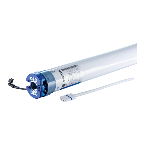
P5/20C...L120/11C
Version: PSF+
Assembly and Operating Instructions
en
Sun protection drives with integrated radio receiver
Important information for:
• Fitters / • Electricians / • Users
Please forward accordingly!
These instructions must be kept safe for future reference.
Becker-Antriebe GmbH
Friedrich-Ebert-Straße 2-4
35764 Sinn/Germany
www.becker-antriebe.com
Advertisement
Table of Contents

Subscribe to Our Youtube Channel
Related Manuals for Becker PSF+ Series


Summary of Contents for Becker PSF+ Series
- Page 1 Assembly and Operating Instructions Sun protection drives with integrated radio receiver Important information for: • Fitters / • Electricians / • Users Please forward accordingly! These instructions must be kept safe for future reference. Becker-Antriebe GmbH Friedrich-Ebert-Straße 2-4 35764 Sinn/Germany www.becker-antriebe.com...
-
Page 2: Table Of Contents
Table of contents General .................................... 3 Warranty ..................................... 3 Safety instructions ................................ 4 Instructions for the user.............................. 4 Instructions for installation and commissioning........................ 4 Intended use .................................. 5 Assembling and disassembling the plug-in connecting cable.................... 6 Assembling the plug-in connecting cable .......................... 6 Disassembling the plug-in connecting cable for tubular drives dia. -
Page 3: General
General These tubular drives are high-quality products with the following features: • Optimised for sun protection applications • Suitable for awnings and conservatory shades. Drives of type "+" are specially designed for cassette awnings • Individual, group and central radio control •... -
Page 4: Safety Instructions
Safety instructions The following safety instructions and warnings are intended to avert hazards and to prevent property damage and personal injury. Instructions for the user General information • All work, including maintenance and cleaning, on electrical installations as well as other system parts must always be performed by authorised specialists, in particular qualified electricians. -
Page 5: Intended Use
• Moving parts of drives must be installed at a height of over 2.5 m above floor level or any other surface from which access to the drive is gained. • To ensure safe operation of the system after commissioning, the limit positions must be correctly set/ programmed in. -
Page 6: Assembling And Disassembling The Plug-In Connecting Cable
Assembling and disassembling the plug-in connecting cable Assembling the plug-in connecting cable Insert the dead connecting cable into the drive head until the locating lug clicks into place in the drive. If necessary, use a suitable flathead screwdriver to assist with insertion. Set the screwdriver into one of the two plug grooves provided for this purpose. Check that the cable is properly engaged. -
Page 7: Disassembling The Plug-In Connecting Cable For Tubular Drives Dia. 45 And Dia. 58
Disassembling the plug-in connecting cable for tubular drives dia. 45 and dia. 58 Caution Prior to disassembly, the power supply to the connecting cable must be disconnected. On drives with a diameter Ø45 or Ø58, insert a suitable flathead screwdriver right into the recess of the locating latch, so that the latch releases the locating lug from the plug. -
Page 8: Installation
Installation Assembling the drive Attention To connect the drive to the driven part, solely mechanical accessory components made by the drive manufacturer from the current product catalogue may be used. Prior to mounting, the fitter must ensure that the masonry and the system being motorised are sufficiently robust (drive torque plus weight of the shading solution). -
Page 9: Assembling The Drive Adapter With Screw Connection
Assembling the drive adapter with screw connection Put the drive adapter (1) onto the drive shaft of the tubular drive. For the assembly, use an M6 x 12 screw (3) with appropriate washer (2) and suitable screw retainer. Threaded hole (4) Securing the drive against axial displacement In order to secure the drive against axial displacement, we recommend screwing the drive adapter to the tube. -
Page 10: Mounting The Drive In The Tube
Mounting the drive in the tube For profile tubes: In the case of some drive adapters, tolerances of the groove widths in different bar- rels can be offset by rotating the drive adapter into a different groove recess. These groove recesses have different sizes and allow the drive to fit exactly. For round tubes: First notch the tube on the motor side, so the lug of the thrust ring can also be pushed into the tube. -
Page 11: First Operation
First operation Explanation of symbols Retract button STOP button Extend button Programming button The tubular drive clicks once to confirm The tubular drive clicks twice to confirm The tubular drive clicks 3 times to confirm 1 = direction switch 2 = radio switch Attention The tubular drives are designed for short-time operation. -
Page 12: Intelligent Installation Management
If several tubular drives are to be connected in parallel, you can deactivate the program- ming mode on one tubular drive by switching the radio switch to the outside position after turning the power on. Readying the tubular drive for programming with the radio switch Switch the radio switch to the inside position. -
Page 13: Setting The Limit Positions
Changing direction of rotation via the master transmitter It is only possible to change the direction of rotation if no limit position has been set. Press the UP or DOWN button. ▻ The shading solution runs in the desired direction. ►... -
Page 14: Changing The Set Limit Positions
Extended position to retracted stop Open to the desired extended limit position. Press the programming button and, within 3 seconds, also press the extend button and hold the two buttons down. ▻ The tubular drive makes a “click” sound to confirm. Then retract to the permanent stop. -
Page 15: Deleting The Limit Positions
Deleting the limit positions Attention When both or individual limit positions are deleted, all the other set functions (intermediate position I, intermediate position II) are deleted as well. Once set, the limit positions can only be deleted with the master transmitter. Deleting individual limit positions Open/close to the limit position to be deleted. -
Page 16: Programming Additional Transmitters
Deleting the desired intermediate position Open/close the shading solution to the desired intermediate position. Press the STOP button and, within 3 seconds, also press the travel button assigned to the intermediate position and hold the two buttons down. ▻ The tubular drive makes a clicking sound to confirm. ►... -
Page 17: Overwriting The Master
Deleting all transmitters (except the master transmitter) Press the programming button on the master transmitter for 3 seconds. ▻ The tubular drive makes a “click” sound to confirm. Re-press the programming button on the master transmitter for 3 seconds. ▻ The tubular drive makes a “click” sound to confirm. Re-press the programming button on the master transmitter for 10 seconds. -
Page 18: Disposal
Readying the tubular drive for programming with the radio switch Switch the radio switch to the inside position. If the radio switch is already in this posi- tion, switch it to the outside and back to the inside position. ▻ The tubular drive is ready to programme for 3 minutes. Now press the programming button of the new master transmitter for 10 seconds. -
Page 19: Technical Data Dia. 45
Technical data dia. 45 Type R8/17C PSF R12/17C R20/17C R30/17C R40/17C R50/11C PSF(+) PSF(+) PSF(+) PSF(+) PSF(+) Rated torque [Nm] Output speed [rpm] Limit switch range 64 revolutions Supply voltage 230 V AC / 50 Hz Connected load [W] Rated current consumption 0.45 0.50 0.75... -
Page 20: What To Do If
Type L70/17C PSF(+) L80/11C PSF(+) L60/17C PSF(+)* L120/11C PSF(+) Rated torque [Nm] Output speed [rpm] Limit switch range 64 revolutions Supply voltage 230 V AC / 50 Hz Connected load [W] Rated current consumption 1.90 1.40 2.10 1.90 Mode S2 4 min Degree of protection IP 44 Min. -
Page 21: Sample Wiring Diagram
Sample wiring diagram... -
Page 22: Declaration Of Conformity
Declaration of conformity... - Page 24 2010 300 513 0c 29/07/2015 ...
Need help?
Do you have a question about the PSF+ Series and is the answer not in the manual?
Questions and answers