Table of Contents
Advertisement
Quick Links
P5-16...R40-17
Model: N01
Assembly and Operating Instructions
en
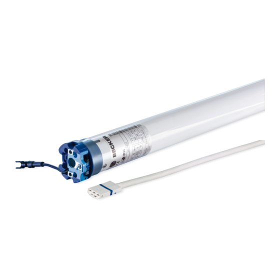
Roller shutter drive with integrated radio
transceiver
Important information for:
• Fitters / • Electricians / • Users
Please forward accordingly!
These instructions must be kept safe for future reference.
2010 301 121 0b 05/12/2022
Becker-Antriebe GmbH
Friedrich-Ebert-Straße 2-4
35764 Sinn/Germany
www.becker-antriebe.com
Advertisement
Table of Contents

Related Manuals for Becker P5-16-N01


Summary of Contents for Becker P5-16-N01
- Page 1 Roller shutter drive with integrated radio transceiver Important information for: • Fitters / • Electricians / • Users Please forward accordingly! These instructions must be kept safe for future reference. 2010 301 121 0b 05/12/2022 Becker-Antriebe GmbH Friedrich-Ebert-Straße 2-4 35764 Sinn/Germany www.becker-antriebe.com...
-
Page 2: Table Of Contents
Table of contents General .................................... 3 Warranty ..................................... 4 Safety instructions ................................ 4 Instructions for the user.............................. 4 Instructions for installation and commissioning........................ 4 Intended use .................................. 6 Assembling and disassembling the plug-in connecting cable.................... 6 Assembly .................................... 7 Antenna installation................................ 9 First operation ................................... -
Page 3: General
General These tubular drives are high-quality products with the following features: • Optimised for roller shutter operation • Individual, group and central radio control • No need to run wires to a switch or relay control device • Any combination of drive and transmitter possible •... -
Page 4: Warranty
Warranty Structural modifications and incorrect installation which are not in accordance with these and our other instructions can result in serious injuries, e.g., crushing of limbs. Therefore, structural modifications may only be carried out with our prior approval and strictly in accordance with our instructions, particularly the information contained in these Assembly and Operating Instructions. Any further processing of the products which does not comply with their intended use is not permitted. - Page 5 • Hazardous moving parts of the drive must be installed at a height of over 2.5 m above floor level or any other surface from which the drive can be accessed. • To ensure safe operation of the system after commissioning, the limit positions must be correctly set/ programmed in.
-
Page 6: Intended Use
Intended use The type of tubular drive described in these instructions is intended solely for the operation of roller shutters. This tubular drive type is compatible with the EnOcean wireless standard and uses the profiles mentioned in the chapter "Supported profiles". This type of tubular drive supports not only curtain attachment by means of springs but also rigid shaft connectors, such as mech- anical anti-lifting devices manufactured by Zurfluh-Feller, Simu, GAH Alberts and Deprat. -
Page 7: Assembly
Disassembling the plug-in connecting cable for tubular drives Insert a suitable flathead screwdriver between the locating lug Ø35 and the snap-in pin, so that the snap-in pin releases the locat- ing lug from the plug. Now you can pull out the connecting cable along with the flat- head screwdriver. - Page 8 Assembling and disassembling the mounting pin Ø45 When pushed in, the mounting pin (2) locks automatically. To undo the mounting pin (2), push the tab washer (1) upwards and pull out the mounting pin (2). If you wish to use the "obstacle detection" function, you must use the "drive adapter for obstacle detection".
-
Page 9: Antenna Installation
Size of drive Drive adapter Torque Fastening screws [mm] max. [Nm] (4 units) dia. 35-dia. 45 Up to 50 Self-tapping screw dia. 4.8 x 9.5 mm We also recommend screwing the idler to the barrel. Attention Do not hammer the tubular drive into the tube or drop it into the barrel! The curtain can only be secured using springs or rigid shaft connectors. -
Page 10: First Operation
First operation Explanation of symbols UP button STOP button DOWN button Programming button (on the transmitter) Receiver confirms once or multiple times by "clicking" or "shifting" 1 = direction switch 2 = radio switch Connecting the tubular drive 230V AC / 50 Hz Connect the tubular drive to the power supply. -
Page 11: Programming Transmitter
Programming transmitter Put the tubular drive into programming mode. Press a travel button 3 times within two seconds. <2s ▻ The tubular drive confirms. ► Programming is now complete. Clear transmitter Put the tubular drive into programming mode. Press a travel button 3 times within two seconds. <2s ▻... -
Page 12: Setting The Limit Positions
Setting the limit positions The running direction must be correct. When setting the limit positions, the tubular drive runs in dead-man mode with the limit position status indicator. The upper limit position must always be set first. When setting the upper limit position, ensure that the roller shut- ter curtain is not pulled out of the guide tracks. - Page 13 Press a travel button 4 times within one second to exit the installation mode. <1s ► The tubular drive confirms. Upper stop to lower point Open to the permanent upper stop. ▻ The tubular drive switches off automatically. Put the tubular drive into programming mode. Press a travel button for >5 seconds on a transmitter that has already been pro- >5s grammed in order to switch to installation mode.
-
Page 14: Deleting The Limit Positions
Deleting the limit positions Attention When the limit positions are deleted, all the other set functions (intermediate position I, in- termediate position II, upper anti-freeze mechanism, obstacle detection, fly screen pro- tection function) are deleted as well. Deleted limit positions are displayed on the limit position status indicator. Deleting a limit position when 2 limit positions are programmed Put the tubular drive into programming mode. -
Page 15: Intermediate Positions I + Ii
Intermediate positions I + II The intermediate positions I + II are freely selectable positions for the shading solution between the two limit positions. Each travel button can be assigned one intermediate posi- tion. Both limit positions must be set before an intermediate position is set. Setting the desired intermediate position Use a short drive command to move the shading solution in the direction of the de- sired intermediate position. -
Page 16: Deleting Transmitters / Window Handles
Deleting transmitters / window handles Deleting transmitters Put the tubular drive into programming mode. Press a travel button 3 times within 2 seconds on the transmitter to be deleted. <2s ▻ The tubular drive confirms. ► The transmitter has now been deleted. Deleting window handles Put the tubular drive into programming mode. -
Page 17: Possible Configurations With The Remote Commissioning Software
The following are detected: Moving DOWN • A curtain jam when closing due to objects on the window sill or sticking of the lateral guide tracks. To ensure complete closing of the roller shutter curtain at the lower limit position, the curtain does not reverse once it gets to ap- prox. -
Page 18: Technical Data Dia. 35
Technical data dia. 35 Tubular drive P5-16 P9-16 Model Type C PROF3+ Rated torque [Nm] Output speed [rpm] Limit switch range 64 revolutions Supply voltage 230 V AC / 50 Hz Connected load [W] Rated current consumption [A] 0.36 0.47 Operating mode S2 4 min. Degree of protection IP 44 Min. -
Page 19: Supported Profile
(lower point) followed by the upper limit position. Forgotten security code. Press the “Delete transmitter” button on the Becker universal programming unit (item no. 4935 000 001 0) for 10 seconds to reset the security code to the factory setting. -
Page 20: Sample Wiring Diagram
Sample wiring diagram 20 - en... -
Page 21: Assignment Table For The Tubular Drives
(Consider applying a serial number sticker) grammed Manufacturer's code: 2 = Becker-Antriebe GmbH Project / customer Room Signature Signature Project manager / building contractor Installing company This assignment table is also available to you on our website: www.becker-antriebe.com for the electronic work. 21 - en... -
Page 22: Declaration Of Conformity
Declaration of conformity 22 - en...
Need help?
Do you have a question about the P5-16-N01 and is the answer not in the manual?
Questions and answers