Page 1
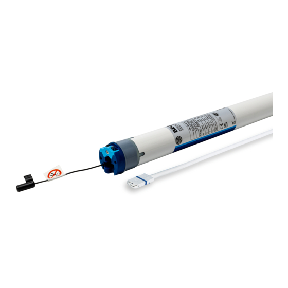
Sun protection drives with integrated radio receiver Important information for: • Fitters / • Electricians / • Users Please forward accordingly! These instructions must be kept safe for future reference. 2010 300 925 0c 19/10/2023 Becker-Antriebe GmbH Friedrich-Ebert-Straße 2-4 35764 Sinn/Germany www.becker-antriebe.com...
Table of contents General .................................... 3 Warranty ..................................... 3 Safety instructions ................................ 4 Instructions for the user.............................. 4 Instructions for installation and commissioning........................ 4 Intended use .................................. 5 Assembling and disassembling the plug-in connecting cable.................... 6 Assembly .................................... 7 First operation .................................. 9 Intelligent installation management ..........................
General These tubular drives are high-quality products with the following features: • Optimised for sun protection applications • Suitable for awnings and conservatory shades. Type "+" drives are specially designed for cassette awnings • Individual, group and central radio control •...
Safety instructions The following safety instructions and warnings are intended to avert hazards and to prevent property damage and personal injury. Instructions for the user General information • The drive must be disconnected from its power source during cleaning and maintenance and when re- placing parts.
• If the drive is used for shading solutions in a specially marked area (e.g., escape routes, hazard zones, safety areas), compliance with all applicable regulations and standards must be ensured. • Once the drive has been installed, the fitter must mark the used tubular drive in the “Technical data” chapter and make a note of the installation position.
Assembling and disassembling the plug-in connecting cable Caution The power supply to the connecting cable must be disconnected prior to assembly/disas- sembly. Assembling the plug-in connecting cable Ø35/Ø45/Ø58 Insert the dead connecting cable into the drive head until the locating lug clicks into place in the drive. If necessary, use a suitable flathead screwdriver to assist with insertion.
Assembly Assembling the drive Attention To connect the drive to the driven part, solely mechanical accessory components made by the drive manufacturer from the current product catalogue may be used. Prior to mounting, the fitter must ensure that the masonry and the system being motorised are sufficiently robust (drive torque plus weight of the shading solution).
Page 8
Mounting the drive in the tube For profile shafts: In the case of some drive adapters, tolerances of the groove widths in different barrels can be offset by rotating the drive adapter into a different groove recess. These groove recesses have different sizes and allow the drive to fit exactly.
First operation Explanation of symbols Retract button STOP button Extend button Programming button (on the transmitter) Receiver confirms once or multiple times by “clicking” or “shifting” 1 = direction switch 2 = radio switch Attention The tubular drives are designed for short-time operation. An inbuilt thermal protection switch prevents overheating of the tubular drive.
Readying the tubular drive for programming with the radio switch Switch the radio switch to the inside position. If the radio switch is already in this posi- tion, switch it to the outside and back to the inside position. ► The tubular drive is ready to programme for 3 minutes Intelligent installation management Completion of installation following automatic setting of limit positions The drive saves the limit position permanently once the upper limit position is reached 3 times in succession.
Changing direction of rotation via master transmitter Press the button. ▻ The shading solution runs in the desired direction. ► The running direction is OK. If the shading solution runs in the wrong direction, the running direction must be changed. Proceed as follows: First, press the programming button, then within 3 seconds also press the button for 3 seconds.
Extended point to retracted stop Open to the desired extended limit position. Press the programming button and, within 3 seconds, also press the extend button and hold the two buttons down. ▻ The tubular drive acknowledges. Then retract to the permanent stop. ▻...
2) Extending the range of travel (the desired limit position is located outside the current range of travel) Attention When both or individual limit positions are deleted, all the other set functions (intermediate position I, intermediate position II) are deleted as well. Open/close to the limit position in the direction in which you wish to extend the range of travel.
Start point to retracted stop Extend Retract Move the sun protection system to the desired maximum projection. This must be at least 2.5 revolutions of the barrel away from the retracted limit position. At this time, it is still possible to amend the position. Then, retract the sun protection system without interruption until the tubular drive switches off automatic- ally.
Deleting both limit positions Any additional functions that may have been set are deleted at the same time, or are reset to the factory default settings. Open/close the shading solution to a point between the limit positions. Press the programming button and, within the next 3 seconds, press the STOP button at the same time and hold the two buttons down for 10 seconds.
Programming additional transmitters In addition to the master transmitter, up to 15 further transmitters can be programmed in the tubular drive. Before programming a radio controlled Sun-Wind-Sensor, the limit posi- tions must be programmed. Press the programming button of the master transmitter for 3 seconds. ▻...
Overwriting the master There are two ways to overwrite the master: • Readying the tubular drive for programming by switching on the power • Readying the tubular drive for programming with the radio switch Readying the tubular drive for programming by switching on the power To ensure that the new master transmitter is programmed in the desired tubular drive only, all other tubular drives which are connected to the same power supply must be deactivated from the programming mode.
Programming and deleting the run times Programming the run times This function is only available with MemoControl transmitters from the Becker Centronic range of control units. This tubular drive can save one switching time for one retraction and one extension cycle.
Obstacle detection Caution Use of the drive’s obstacle detection system as personal protection is not permitted. It has been designed exclusively to protect the sun protection system from being damaged. If the drive is correctly installed, it switches off when it detects obstructions or fabric faults and tries to run past the obstruction a second time.
Disposal The crossed-out bin symbol on the product indicates that the device is subject to mandatory disposal separate from household waste. This product must be handed over to a collection point for electrical and electronic equipment at the end of its service life. The packaging material must be disposed of properly.
Technical data dia. 58 Tubular drive L50-17 L60-11 L60-17 L70-17 Model Type C PSF+ V1 Rated torque [Nm] Output speed [rpm] Limit switch range 64 revolutions Supply voltage 230 V AC / 50 Hz Connected load [W] Rated current consumption 1.40 1.20 1.75 1.90 Operating mode S2 4 min Degree of protection...
What to do if...? Problem Remedy Tubular drive does not move. Program new transmitter. Bring transmitter within range of the tubular drive. Press drive or stop button on transmitter at least five times in the immediate vicinity of the tubular drive. Insert battery/batteries correctly in the transmitter or insert new battery/batteries.
Declaration of conformity For UK-Markets: The Declaration of Conformity can be provided upon request from Becker Motors Ltd., or can be downloaded on www.beckermo- tors.co.uk. 23 - en...
Need help?
Do you have a question about the P9-16-C12 and is the answer not in the manual?
Questions and answers