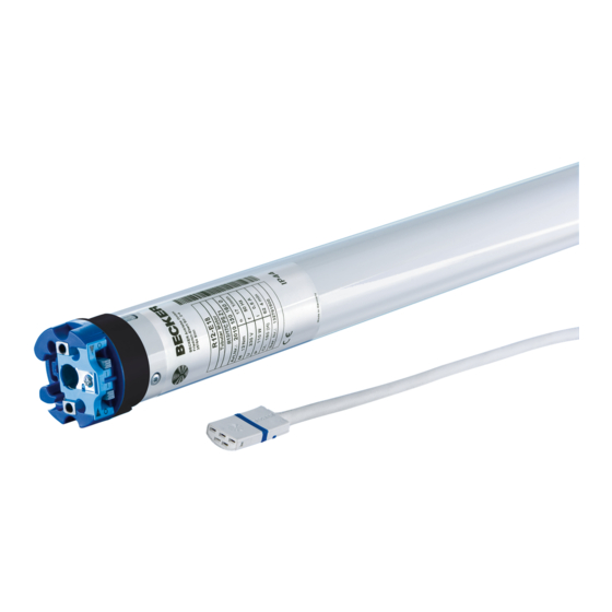
Becker R12-17 Assembly And Operating Instructions Manual
Tubular drives for zip systems
Hide thumbs
Also See for R12-17:
- Assembly and operating instructions manual (36 pages) ,
- Assembly and operating instructions manual (20 pages) ,
- Assembly and operating instructions manual (28 pages)
Table of Contents
Advertisement
Quick Links
R12-17...R40-17
Model: E18a
Assembly and Operating Instructions
en
Tubular drives for ZIP systems
Important information for:
• Fitters / • Electricians / • Users
Please forward accordingly!
These instructions must be kept safe for future reference.
2010 301 098 0 14/08/2018
Becker-Antriebe GmbH
Friedrich-Ebert-Straße 2-4
35764 Sinn/Germany
www.becker-antriebe.com
Advertisement
Table of Contents

Related Manuals for Becker R12-17


Summary of Contents for Becker R12-17
- Page 1 R12-17...R40-17 Model: E18a Assembly and Operating Instructions Tubular drives for ZIP systems Important information for: • Fitters / • Electricians / • Users Please forward accordingly! These instructions must be kept safe for future reference. 2010 301 098 0 14/08/2018 Becker-Antriebe GmbH Friedrich-Ebert-Straße 2-4...
-
Page 2: Table Of Contents
Table of contents General .................................... 3 Warranty ..................................... 3 Safety instructions ................................ 4 Instructions for the user.............................. 4 Instructions for installation and commissioning........................ 4 Intended use .................................. 6 Assembling and disassembling the plug-in connecting cable.................... 6 Assembling the plug-in connecting cable .......................... 6 Disassembling the plug-in connecting cable for tubular drives dia. -
Page 3: General
General These tubular drives are high-quality products with the following features: • Optimised for vertical ZIP applications • Installation without stops is also possible (from extended point to retracted point) • Automatic detection of limit positions thanks to intelligent electronic system with stop systems •... -
Page 4: Safety Instructions
Safety instructions The following safety instructions and warnings are intended to avert hazards and to prevent property damage and personal injury. Instructions for the user General information • The drive must be disconnected from its power source during cleaning and maintenance and when re- placing parts. - Page 5 • Hazardous moving parts of the drive must be installed at a height of over 2.5 m above floor level or any other surface from which the drive can be accessed. • To ensure safe operation of the system after commissioning, the limit positions must be correctly set/ programmed in.
-
Page 6: Intended Use
Intended use The type of tubular drive described in these instructions is intended solely for the operation of vertical ZIP systems. It may only be used in networked systems if all the individual drives are exactly synchronised and reach their limit positions at the same time. -
Page 7: Disassembling The Plug-In Connecting Cable For Tubular Drives Dia. 45 And Dia. 58
Disassembling the plug-in connecting cable for tubular drives dia. 45 and dia. 58 Caution Prior to disassembly, the power supply to the connecting cable must be disconnected. Insert a suitable flathead screwdriver right into the recess of the locating latch, so that the latch releases the locating lug from the plug. -
Page 8: Installation
Installation Assembling the drive Attention To connect the drive to the driven part, solely mechanical accessory components made by the drive manufacturer from the current product catalogue may be used. Prior to mounting, the fitter must ensure that the masonry and the system being motorised are sufficiently robust (drive torque plus weight of the shading solution). -
Page 9: Disassembling The Drive Adapter With Safety Catch On The Drive Shaft
Disassembling the drive adapter with safety catch on the drive shaft Disassembly with disassembly tool, Item no. 4930 300 606 0 Disassembly with long nose pliers Assembling and disassembling the drive adapter with separate drive adapter safety catch Assembling and disassembling the drive adapter with screw connection Mounting the drive in the tube For profile tubes: In the case of some drive adapters, tolerances of the groove widths in different bar-... - Page 10 For round shafts: Measure the lug of the thrust ring (X, Y). Then notch the tube on the motor side, so the lug of the thrust ring can also be pushed into the shaft. There must be no play between the lug of the thrust ring and the shaft. To ensure secure torque transmission for round shafts, we recommend screwing the drive adapter to the shaft (see the table below).
-
Page 11: Setting The Limit Positions With The Switches On The Drive Head
Setting the limit positions with the switches on the drive head Intelligent installation management Limit position status indicator A brief stopping and restarting indicates that no limit position has been set in that direction of movement. Completion of installation following automatic setting of limit position "Stop" The drive saves the limit position "Stop"... - Page 12 Lower point to upper point There is no shading solution length adjustment with this limit position setting. Set both switches to the delete setting. Execute a short drive command. Close to the desired lower limit position. Reset the switch of the DOWN direction of rotation from the delete setting to the pro- gramming setting.
-
Page 13: Deleting The Limit Positions With The Switches
Deleting the limit positions with the switches Deleting individual limit positions It is only possible to delete an individual limit position if lower point to upper point without stops was programmed with the switches. Reset the switch of the corresponding limit position from the programming setting to the delete setting. -
Page 14: Setting The Limit Positions Using The Programming Unit
Setting the limit positions using the programming unit Intelligent installation management Limit position status indicator A brief stopping and restarting indicates that no limit position has been set in that direction of movement. Completion of installation following automatic setting of limit position "Stop" The drive saves the limit position "Stop"... - Page 15 Lower point to upper point with programming unit There is no shading solution length adjustment with this limit position setting. Set both switches to the programming setting. Close to the desired lower limit position. Press the programming button of the programming unit for 3 seconds. ▻...
-
Page 16: Deleting The Limit Positions Using The Programming Unit
Deleting the limit positions using the programming unit Connect the wires of the tubular drive to those of the same colour in the programming unit and switch on the power supply. Please pause for 1 sec after the last drive command before beginning the deletion se- quence. - Page 17 Deleting both limit positions Any additional functions that may have been set are deleted at the same time, or are reset to the factory default settings. Open/close the shading solution to a point between the limit positions. Press the programming button and keep it pressed. Then press down the travel button and keep it pressed.
-
Page 18: Adjusting The Limit Positions With A Rotary Switch Or A Locking Button
Adjusting the limit positions with a rotary switch or a locking button Intelligent installation management Limit position status indicator A brief stopping and restarting indicates that no limit position has been set in that direction of movement. Completion of installation following automatic setting of limit position "Stop" The drive saves the limit position "Stop"... -
Page 19: Deleting The Limit Positions With A Rotary Switch Or A Locking Button
Lower point to upper stop Set both switches to the programming setting. Close to the desired lower limit position. Carry out the following sequence without interruption between the individual drive commands. ▻ The tubular drive makes a "click" sound to confirm. until STOP and hold until Then open to the permanent upper stop. -
Page 20: Setting The Limit Positions With Auto-Install (For Zip Applications With Heavy End Strip)
Setting the limit positions with Auto-install (for ZIP applications with heavy end strip) For proper execution of the auto-install function, the necessary torque in the lower limit position must be at least 1/3 of the rated torque of the tubular drive used. Example: Tubular drive 12 Nm, barrel diameter 85 mm (r= 0.0425 m, no part of the shading solution is on the barrel when uncoiled). -
Page 21: Activating/Deactivating The Additional Fabric Untensioning Function With The Programming Unit
Activating/deactivating the additional fabric untensioning function with the programming unit The "to retracted stop" limit position must be set for the fabric untensioning function. On delivery, the fabric untensioning function is activated. To deactivate it, move to the Retract limit position. Press the program- ming button for approx. -
Page 22: Technical Data Dia. 45
Technical data dia. 45 Tubular drive R12-17 R20-17 R30-17 R40-17 Model E18a Type C PSO Z1 A Rated torque [Nm] Output speed [rpm] Limit switch range 64 revolutions Supply voltage 240 V AC / 50 Hz Connected load [W] Rated current consumption [A] 0.50 0.70 0.95 1.10... -
Page 23: What To Do If
What to do if...? Problem Remedy Tubular drive overruns the limit position or does not reach the Repair electrical installation and re-program limit positions. set limit position. Check electrical installation; remove external devices; reset limit positions. Stops have broken off or one or several attachments are broken. -
Page 24: Sample Wiring Diagram
Sample wiring diagram Controlling one/several drive(s) via a single switch/button...
Need help?
Do you have a question about the R12-17 and is the answer not in the manual?
Questions and answers