Table of Contents
Advertisement
Quick Links
R12-17...R40-17
Model: C01a
Assembly and Operating Instructions
en
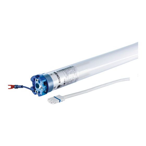
Roller shutter drive with integrated radio receiver
915.3 Mhz
Important information for:
• Fitters / • Electricians / • Users
Please forward accordingly!
These instructions must be kept safe for future reference.
2010 300 570 0d 14/08/2018
Becker-Antriebe GmbH
Friedrich-Ebert-Straße 2-4
35764 Sinn/Germany
www.becker-antriebe.com
Advertisement
Table of Contents

Related Manuals for Becker C01a


Summary of Contents for Becker C01a
- Page 1 R12-17...R40-17 Model: C01a Assembly and Operating Instructions Roller shutter drive with integrated radio receiver 915.3 Mhz Important information for: • Fitters / • Electricians / • Users Please forward accordingly! These instructions must be kept safe for future reference. 2010 300 570 0d 14/08/2018 ...
-
Page 2: Table Of Contents
Table of contents General .................................... 3 Warranty ..................................... 4 Safety instructions ................................ 4 Instructions for the user.............................. 4 Instructions for installation and commissioning........................ 4 Intended use .................................. 6 Assembling and disassembling the plug-in connecting cable.................... 6 Assembling the plug-in connecting cable .......................... 6 Disassembling the plug-in connecting cable for tubular drives dia. -
Page 3: General
General These tubular drives are high-quality products with the following features: • Optimised for roller shutter operation • Individual, group and central radio control • No need to run wires to a switch or relay control device • Any combination of drive and transmitter possible •... -
Page 4: Warranty
Warranty Structural modifications and incorrect installation which are not in accordance with these and our other instructions can result in serious injuries, e.g., crushing of limbs. Therefore, structural modifications may only be carried out with our prior approval and strictly in accordance with our instructions, particularly the information contained in these Assembly and Operating Instructions. Any further processing of the products which does not comply with their intended use is not permitted. - Page 5 your safety and the safety of others. This means that the use of unapproved third-party products, or modifications which have not been agreed with or approved by us, are prohibited. We do not accept li- ability for damage or injury arising from such actions. •...
-
Page 6: Intended Use
Intended use The type of tubular drive described in these instructions is intended solely for the operation of roller shutters. This type of tubular drive supports not only curtain attachment by means of springs but also mechanical anti-lifting devices (e.g., Zurfluh-Feller, Simu, GAH Alberts and Deprat). -
Page 7: Disassembling The Plug-In Connecting Cable For Tubular Drives Dia. 45 And Dia. 58
Disassembling the plug-in connecting cable for tubular drives dia. 45 and dia. 58 Caution Prior to disassembly, the power supply to the connecting cable must be disconnected. Insert a suitable flathead screwdriver right into the recess of the locating latch, so that the latch releases the locating lug from the plug. -
Page 8: Installation
Installation Assembling the drive Attention To connect the drive to the driven part, solely mechanical accessory components made by the drive manufacturer from the current product catalogue may be used. Prior to mounting, the fitter must ensure that the masonry and the system being motorised are sufficiently robust (drive torque plus weight of the shading solution). -
Page 9: Drive Adapter Safety Catch
Drive adapter safety catch Assembling the drive adapter with safety catch on the drive shaft Disassembling the drive adapter with safety catch on the drive shaft Disassembly with disassembly tool, Item no. 4930 300 606 0 Disassembly with long nose pliers Assembling and disassembling the drive adapter with separate drive adapter safety catch Assembling and disassembling the drive adapter with screw connection... -
Page 10: Mounting The Drive In The Tube
Mounting the drive in the tube For profile tubes: In the case of some drive adapters, tolerances of the groove widths in different bar- rels can be offset by rotating the drive adapter into a different groove recess. These groove recesses have different sizes and allow the drive to fit exactly. For round shafts: Measure the lug of the thrust ring (X, Y). -
Page 11: Confirming The Drive
Confirming the drive The drive confirms each programming and deletion action. The tubular drive does this through a small movement that can be per- ceived (audibly) as "clicking" or (visually) as "shifting". -
Page 12: First Operation
First operation Explanation of symbols UP button STOP button DOWN button Programming button The tubular drive clicks to confirm (One or more times) The tubular drive shifts to confirm (One or more times) 1 = direction switch 2 = radio switch Attention The tubular drives are designed for short-time operation. -
Page 13: Programming The Master Transmitter
Readying the tubular drive for programming with the radio switch Switch the radio switch to the inside position. If the radio switch is already in this posi- tion, switch it to the outside and back to the inside position. ► The tubular drive is ready to programme for 3 minutes Programming the master transmitter Press the programming button for 3 seconds when it is ready to programme. -
Page 14: Intelligent Installation Management
Changing direction of rotation via master transmitter It is only possible to change the direction of rotation if no limit position has been set. Press the UP or DOWN button ▻ The shading solution runs in the desired direction. ► The running direction is OK. If the shading solution runs in the wrong direction, the running direction must be changed. - Page 15 Upper point to lower point There is no shading solution length adjustment with this limit position setting. Open to the desired upper limit position. Press the programming button and, within 3 seconds, also press the UP button and hold the two buttons down. ▻...
-
Page 16: Changing The Set Limit Positions
Changing the set limit positions Once set, the limit positions can only be changed with the master transmitter. 1) Shortening the range of travel (the desired limit position is located inside the current range of travel) Open/close to the desired new limit position. Press the programming button and, within 3 seconds, also press the DOWN button for the lower limit position or the UP button for the upper limit position and hold the two buttons down. -
Page 17: Intermediate Positions I + Ii
Deleting individual limit positions Open/close to the limit position to be deleted. Press the programming button and, within 3 seconds, also press the STOP button and hold the two buttons down for 10 seconds. ▻ The tubular drive acknowledges. ► The limit position is now deleted. Deleting both limit positions Open/close the shading solution to a point between the limit positions. -
Page 18: Programming Additional Transmitters
Deleting the desired intermediate position Move the shading solution to the intermediate position that is to be deleted. Now press the STOP button and, within 3 seconds, also press the travel button as- signed to the intermediate position and hold the two buttons down. ▻... -
Page 19: Overwriting The Master
Deleting all transmitters (except the master transmitter) Press the programming button on the master transmitter for 3 seconds. ▻ The tubular drive acknowledges. Re-press the programming button on the master transmitter for 3 seconds. ▻ The tubular drive acknowledges. Re-press the programming button on the master transmitter for 10 seconds. ▻... - Page 20 Readying the tubular drive for programming with the radio switch Switch the radio switch to the inside position. If the radio switch is already in this posi- tion, switch it to the outside and back to the inside position. ▻ The tubular drive is ready to program for 3 minutes. Now press the programming button of the new master transmitter for 10 seconds.
-
Page 21: Local Operation With A Single Button
Local operation with a single button Wiring Only use a single button (normally open). Connect one button for each drive. The button must not be operated during the first five seconds after the mains voltage has been switched on. Button (normally open) Button commands <... -
Page 22: Upper Anti-Freeze Mechanism
Upper anti-freeze mechanism The upper anti-freeze mechanism helps to prevent the roller shutter from freezing in the upper limit position, as the roller shutter stops just before the upper stop. The distance from the upper stop is automatically cyclically checked and, if necessary, correc- ted. -
Page 23: Fly Screen Protection Function
Maintenance These drives are maintenance-free. Technical data dia. 45 Tubular drive R12-17 R20-17 R30-17 R40-17 Model C01a Type CPROF+ A2 Rated torque [Nm] Output speed [rpm] Limit switch range 64 revolutions Supply voltage 240 V AC / 50 Hz Connected load [W] Rated current consumption [A] 0.50... -
Page 24: Certificate Of Suitability
Certificate of Suitability Certificate No.: SAA181406 What to do if...? Problem Remedy Tubular drive is not functioning. Program new transmitter. Bring transmitter within range of the tubular drive. Press drive or stop button on transmitter at least 5 times in the immediate vicinity of the tubular drive. -
Page 25: Sample Wiring Diagram
Sample wiring diagram...
Need help?
Do you have a question about the C01a and is the answer not in the manual?
Questions and answers