Table of Contents
Advertisement
Quick Links
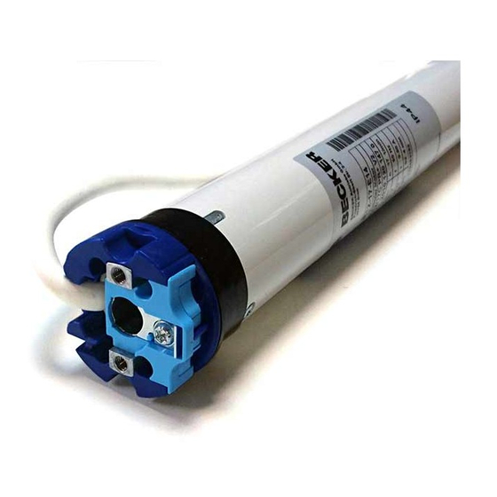
R8/17...R40/17
Model: E14
Assembly and Operating Instructions
en
Tubular drives for roller shutters
Important information for:
• Fitters / • Electricians / • Users
Please forward accordingly!
These instructions must be kept safe for future reference.
2010 300 911 0a 27/02/2024
Becker-Antriebe GmbH
Friedrich-Ebert-Straße 2-4
35764 Sinn/Germany
info@becker-antriebe.com
www.becker-antriebe.com
Advertisement
Table of Contents

Related Manuals for Becker E14


Summary of Contents for Becker E14
- Page 1 R8/17...R40/17 Model: E14 Assembly and Operating Instructions Tubular drives for roller shutters Important information for: • Fitters / • Electricians / • Users Please forward accordingly! These instructions must be kept safe for future reference. 2010 300 911 0a 27/02/2024 Becker-Antriebe GmbH Friedrich-Ebert-Straße 2-4...
-
Page 2: Table Of Contents
Table of contents General .................................... 3 Warranty ..................................... 3 Safety instructions ................................ 4 Instructions for the user.............................. 4 Instructions for installation and commissioning........................ 4 Intended use .................................. 6 Assembling and disassembling the plug-in connecting cable.................... 6 Assembly .................................... 7 Setting the limit positions using the programming unit...................... 10 Deleting the limit positions using the programming unit ...................... -
Page 3: General
General These tubular drives are high-quality products with the following features: • Optimised for roller shutter operation • Installation without stops possible (from lower point to upper point) • Easy setting of limit positions by pushing a button on the programming unit, via a rotary switch or a locking button •... -
Page 4: Safety Instructions
Safety instructions The following safety instructions and warnings are intended to avert hazards and to prevent property damage and personal injury. Instructions for the user General information • The drive must be disconnected from its power source during cleaning and maintenance and when re- placing parts. - Page 5 • If the drive is used for shading solutions in a specially marked area (e.g., escape routes, hazard zones, safety areas), compliance with all applicable regulations and standards must be ensured. • Once the drive has been installed, the fitter must mark the used tubular drive in the “Technical data” chapter and make a note of the installation position.
-
Page 6: Intended Use
Intended use The type of tubular drive described in these instructions is intended solely for the operation of roller shutters. This type of tubular drive supports not only curtain attachment by means of springs but also rigid shaft connectors, such as mech- anical anti-lifting devices manufactured by Zurfluh-Feller, Simu, GAH Alberts and Deprat. -
Page 7: Assembly
Assembly Assembling the drive Attention To connect the drive to the driven part, solely mechanical accessory components made by the drive manufacturer from the current product catalogue may be used. Prior to mounting, the fitter must ensure that the masonry and the system being motorised are sufficiently robust (drive torque plus weight of the shading solution). - Page 8 Assembling and disassembling the drive adapter with drive adapter safety catch or screw connection Assembling and disassembling the drive Assembling and disassembling the drive adapter with separate drive adapter adapter with screw connection safety catch Mounting the drive in the tube For profile shafts: In the case of some drive adapters, tolerances of the groove widths in different barrels can be offset by rotating the drive adapter into a different groove recess.
- Page 9 Lay the connecting cable Lay the connecting cable up to the tubular drive, and fix. The connecting cable must not project into the winding chamber. The exterior antenna, if present, must not be shortened or damaged under any cir- cumstances and must not project into the winding space. Cover any sharp edges. 9 - en...
-
Page 10: Setting The Limit Positions Using The Programming Unit
Setting the limit positions using the programming unit Programming unit for drives with electronic limit switching. Programming button Travel button Attention The programming unit is only designed for the commissioning, not for continuous opera- tion. Intelligent installation management Completion of installation following automatic setting of limit position "Stop" Next time the “stop”... - Page 11 Upper point to lower point There is no shading solution length adjustment with this limit position setting. Open to the desired upper limit position. Press the programming button of the programming unit for 3 seconds. ▻ The tubular drive acknowledges. Then close to the desired lower limit position.
-
Page 12: Deleting The Limit Positions Using The Programming Unit
Deleting the limit positions using the programming unit Connect the wires of the tubular drive to those of the same colour in the programming unit and switch on the power supply. Please pause for 1 sec after the last drive command before beginning the deletion se- quence. -
Page 13: Adjusting The Limit Positions With A Rotary Switch Or A Locking Button
Deleting both limit positions Open/close the shading solution to a point between the limit positions. Press the programming button and keep it pressed. Then press down the travel button and keep it pressed. Now release the programming button, but continue to keep the travel button pressed. Next press the programming button again. - Page 14 Upper point to lower point There is no shading solution length adjustment with this limit position setting. Open to the desired upper limit position. Carry out the following sequence without interruption between the individual drive commands. ▻ The tubular drive acknowledges. until STOP and hold until Then close to the desired lower limit position.
-
Page 15: Deleting The Limit Positions With A Rotary Switch Or A Locking Button
Deleting the limit positions with a rotary switch or a locking button The switching commands sequence must be carried out in quick succession. Any addi- tional functions that have been set are retained. Carry out the following deletion sequence without interruption between the individual drive commands: STOP until The tubular drive confirms. -
Page 16: Torque Detection
Torque detection A correctly installed tubular drive reacts to extraordinarily large increases in load during operation between the limit positions and thereby prevents an overload of the tubular drive. Disposal The crossed-out bin symbol on the product indicates that the device is subject to mandatory disposal separate from household waste. -
Page 17: What To Do If
What to do if...? Problem Remedy The roller shutter curtain is raised unevenly or not at all. Repair system; then re-program limit positions. Tubular drive overruns the limit position or does not reach the Repair electrical installation; re-program limit positions. set limit position. -
Page 18: Sample Wiring Diagrams
Sample wiring diagrams The assignment of the black and brown wires according to the direction of travel is de- pendant on how the drive is installed (mounted to the right or to the left). Controlling one/several drive(s) via a single switch/button Central, group and individual control using Centronic UnitControl UC42 Central Control unit... -
Page 19: Declaration Of Conformity
Declaration of conformity 19 - en...
Need help?
Do you have a question about the E14 and is the answer not in the manual?
Questions and answers