Table of Contents
Advertisement
Quick Links
P5-16...R40-17
Model: N01
Assembly and Operating Instructions
en
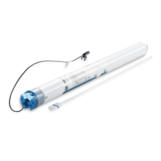
Roller shutter drive with integrated radio
transceiver
Important information for:
• Fitters / • Electricians / • Users
Please forward accordingly!
These instructions must be kept safe for future reference.
2010 301 121 0 28/05/2020
Becker-Antriebe GmbH
Friedrich-Ebert-Straße 2-4
35764 Sinn/Germany
www.becker-antriebe.com
Advertisement
Table of Contents

Related Manuals for Becker enocean P5-16


Summary of Contents for Becker enocean P5-16
- Page 1 Roller shutter drive with integrated radio transceiver Important information for: • Fitters / • Electricians / • Users Please forward accordingly! These instructions must be kept safe for future reference. 2010 301 121 0 28/05/2020 Becker-Antriebe GmbH Friedrich-Ebert-Straße 2-4 35764 Sinn/Germany www.becker-antriebe.com...
-
Page 2: Table Of Contents
Table of contents General .................................... 3 Warranty ..................................... 4 Safety instructions ................................ 4 Instructions for the user.............................. 4 Instructions for installation and commissioning........................ 4 Intended use .................................. 6 Assembling and disassembling the plug-in connecting cable.................... 6 Assembling the plug-in connecting cable .......................... 6 Disassembling the plug-in connecting cable for tubular drives .................... -
Page 3: General
General These tubular drives are high-quality products with the following features: • Optimised for roller shutter operation • Individual, group and central radio control • No need to run wires to a switch or relay control device • Any combination of drive and transmitter possible •... -
Page 4: Warranty
Warranty Structural modifications and incorrect installation which are not in accordance with these and our other instructions can result in serious injuries, e.g., crushing of limbs. Therefore, structural modifications may only be carried out with our prior approval and strictly in accordance with our instructions, particularly the information contained in these Assembly and Operating Instructions. Any further processing of the products which does not comply with their intended use is not permitted. - Page 5 your safety and the safety of others. This means that the use of unapproved third-party products, or modifications which have not been agreed with or approved by us, are prohibited. We do not accept li- ability for damage or injury arising from such actions. •...
-
Page 6: Intended Use
Intended use The type of tubular drive described in these instructions is intended solely for the operation of roller shutters. This tubular drive type is compatible with the EnOcean wireless standard and uses the profiles mentioned in the chapter "Supported profiles". This type of tubular drive supports not only curtain attachment by means of springs but also rigid shaft connectors, such as mech- anical anti-lifting devices manufactured by Zurfluh-Feller, Simu, GAH Alberts and Deprat. -
Page 7: Disassembling The Plug-In Connecting Cable For Tubular Drives
Disassembling the plug-in connecting cable for tubular drives Caution Prior to disassembly, the power supply to the connecting cable must be disconnected. dia. 35 dia. 45 and dia. 58 Insert a suitable flathead screwdriver between the locating lug Insert a suitable flathead screwdriver right into the recess of the and the snap-in pin, so that the snap-in pin releases the locat- locating latch, so that the latch releases the locating lug from ing lug from the plug. -
Page 8: Installation
Installation Assembling the drive Attention To connect the drive to the driven part, solely mechanical accessory components made by the drive manufacturer from the current product catalogue may be used. Prior to mounting, the fitter must ensure that the masonry and the system being motorised are sufficiently robust (drive torque plus weight of the shading solution). -
Page 9: Drive Adapter Safety Catch
Drive adapter safety catch Assembling the drive adapter with safety catch on the drive shaft Disassembling the drive adapter with safety catch on the drive shaft Disassembly with disassembly tool, Item no. 4930 300 606 0 Disassembly with long nose pliers Assembling and disassembling the drive adapter with separate drive adapter safety catch Assembling and disassembling the drive adapter with screw connection 9 - en... -
Page 10: Mounting The Drive In The Tube
Mounting the drive in the tube For profile tubes: In the case of some drive adapters, tolerances of the groove widths in different bar- rels can be offset by rotating the drive adapter into a different groove recess. These groove recesses have different sizes and allow the drive to fit exactly. For round shafts: Measure the lug of the thrust ring (X, Y). -
Page 11: Antenna Installation
Antenna installation Lay and fix the antenna end in the lower part of the box near the guide rail. Attention Make sure that the antenna cannot be detected by the roller shutter curtain. 11 - en... -
Page 12: First Operation
First operation Explanation of symbols UP button STOP button DOWN button Programming button (on the transmitter) Receiver confirms once or multiple times by "clicking" or "shifting" 1 = direction switch 2 = radio switch Connecting the tubular drive 230V AC / 50 Hz Connect the tubular drive to the power supply. -
Page 13: Programming Transmitter
Programming transmitter Put the tubular drive into programming mode. Press a travel button 3 times within two seconds. <2s ▻ The tubular drive confirms. ► Programming is now complete. Clear transmitter Put the tubular drive into programming mode. Press a travel button 3 times within two seconds. <2s ▻... -
Page 14: Upper Stop To Lower Stop
Attention When operating the tubular drive without the drive adapter for obstacle detection, if using springs a point must be set in the lower limit position. There are several ways to set the limit positions: • Upper stop to lower stop •... - Page 15 Upper stop to lower point Open to the permanent upper stop. ▻ The tubular drive switches off automatically. Put the tubular drive into programming mode. Press a travel button for >5 seconds on a transmitter that has already been pro- >5s grammed in order to switch to installation mode.
-
Page 16: Deleting The Limit Positions
Deleting the limit positions Attention When the limit positions are deleted, all the other set functions (intermediate position I, in- termediate position II, upper anti-freeze mechanism, obstacle detection, fly screen pro- tection function) are deleted as well. Deleted limit positions are displayed on the limit position status indicator. Deleting a limit position when 2 limit positions are programmed Put the tubular drive into programming mode. -
Page 17: Intermediate Positions I + Ii
Intermediate positions I + II The intermediate positions I + II are freely selectable positions for the shading solution between the two limit positions. Each travel button can be assigned one intermediate posi- tion. Both limit positions must be set before an intermediate position is set. Setting the desired intermediate position Use a short drive command to move the shading solution in the direction of the de- sired intermediate position. -
Page 18: Deleting Transmitters / Window Handles
Deleting transmitters / window handles Deleting transmitters Put the tubular drive into programming mode. Press a travel button 3 times within 2 seconds on the transmitter to be deleted. <2s ▻ The tubular drive confirms. ► The transmitter has now been deleted. Deleting window handles Put the tubular drive into programming mode. -
Page 19: Obstacle Detection
Obstacle detection Caution Obstacle detection is only active in conjunction with the "drive adapter for obstacle detec- tion". In addition, please note that the drive must be pushed in to the shaft as far as the band of the thrust ring. Use of the drive’s obstacle detection system as personal protection is not permitted. -
Page 20: Remote Management (Reman)
Remote Management (ReMan) The functions LOCK, UNLOCK and SET CODE are only available 5 minutes after switching on the mains voltage for the factory-set security code. The factory-set security code is: 1F5340B9 and must be changed for further use of ReMan / ReCom. Please ensure you keep the current security code in a safe place for future reference. -
Page 21: Technical Data Dia. 45
Technical data dia. 45 Tubular drive R8-17 R12-17 R20-17 R30-17 R40-17 Model Type C PROF+ EN Rated torque [Nm] Output speed [rpm] Limit switch range 64 revolutions Supply voltage 230 V AC / 50 Hz Connected load [W] Rated current consumption [A] 0.45 0.75 1.15 Operating mode S2 4 min. -
Page 22: What To Do If
(lower point) followed by the upper limit position. Forgotten security code. Press the “Delete transmitter” button on the Becker universal programming unit (item no. 4935 000 001 0) for 10 seconds to reset the security code to the factory setting. -
Page 23: Sample Wiring Diagram
Sample wiring diagram 23 - en... -
Page 24: Declaration Of Conformity
Declaration of conformity 24 - en...
Need help?
Do you have a question about the enocean P5-16 and is the answer not in the manual?
Questions and answers