Table of Contents
Advertisement
Quick Links
P5-16...R50-11
Model: E18
Assembly and Operating Instructions
en
Tubular drives for ZIP systems
Important information for:
• Fitters / • Electricians / • Users
Please forward accordingly!
These instructions must be kept safe for future reference.
2010 300 787 0g 08/07/2022
Becker-Antriebe GmbH
Friedrich-Ebert-Straße 2-4
35764 Sinn/Germany
www.becker-antriebe.com
Advertisement
Table of Contents

Related Manuals for Becker P5-30-E18


Summary of Contents for Becker P5-30-E18
- Page 1 Assembly and Operating Instructions Tubular drives for ZIP systems Important information for: • Fitters / • Electricians / • Users Please forward accordingly! These instructions must be kept safe for future reference. 2010 300 787 0g 08/07/2022 Becker-Antriebe GmbH Friedrich-Ebert-Straße 2-4 35764 Sinn/Germany www.becker-antriebe.com...
-
Page 2: Table Of Contents
Table of contents General .................................... 3 Warranty ..................................... 3 Safety instructions ................................ 4 Instructions for the user.............................. 4 Instructions for installation and commissioning........................ 4 Intended use .................................. 6 Assembling and disassembling the plug-in connecting cable.................... 6 Assembly .................................... 7 Setting the limit positions with the switches on the drive head .................... 9 Deleting the limit positions with the switches ........................ -
Page 3: General
General These tubular drives are high-quality products with the following features: • Optimised for vertical ZIP applications • Installation without stops is also possible (from extended point to retracted point) • Automatic detection of limit positions thanks to intelligent electronic system with stop systems •... -
Page 4: Safety Instructions
Safety instructions The following safety instructions and warnings are intended to avert hazards and to prevent property damage and personal injury. Instructions for the user General information • The drive must be disconnected from its power source during cleaning and maintenance and when re- placing parts. - Page 5 • If the drive is used for shading solutions in a specially marked area (e.g., escape routes, hazard zones, safety areas), compliance with all applicable regulations and standards must be ensured. • Once the drive has been installed, the fitter must mark the used tubular drive in the “Technical data” chapter and make a note of the installation position.
-
Page 6: Intended Use
Intended use The type of tubular drive described in these instructions is intended solely for the operation of vertical ZIP systems. It may only be used in networked systems if all the individual drives are exactly synchronised and reach their limit positions at the same time. -
Page 7: Assembly
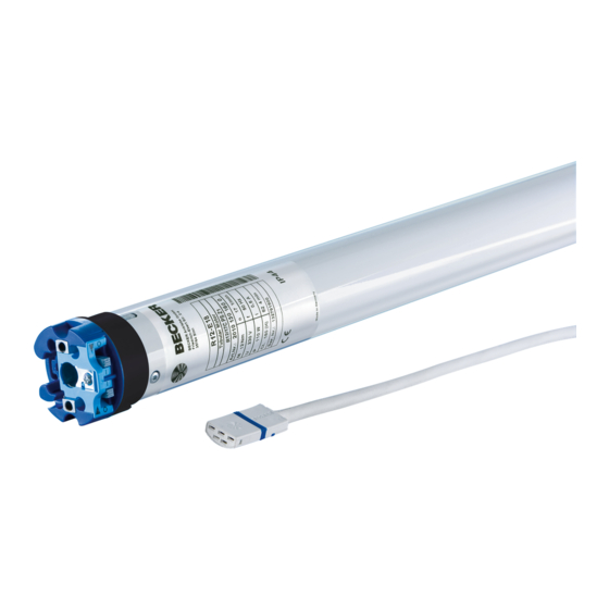
Ø45/Ø58 Insert a suitable flathead screwdriver right into the recess of the locating latch, so that the latch releases the locating lug from the plug. Now you can pull out the connecting cable along with the flat- head screwdriver. A = locating latch Assembly Assembling the drive Attention... - Page 8 Assembling the drive adapter with safety catch on the Disassembling the drive adapter with safety catch on the drive shaft drive shaft Assembling and disassembling the drive adapter with drive adapter safety catch or screw connection Assembling and disassembling the drive Assembling and disassembling the drive adapter with separate drive adapter adapter with screw connection...
-
Page 9: Setting The Limit Positions With The Switches On The Drive Head
Setting the limit positions with the switches on the drive head Intelligent installation management Completion of installation following automatic setting of limit position "Stop" Next time the “stop” limit position is travelled to, this position will be provisionally saved as the limit position. Once the limit position has been detected at this position 3 times in a row without any problems, it will be definitively saved. -
Page 10: Deleting The Limit Positions With The Switches
Lower point to upper point There is no shading solution length adjustment with this limit position setting. Set both switches to the delete setting. Execute a short drive command. Close to the desired lower limit position. Reset the switch of the DOWN direction of rotation from the delete setting to the pro- gramming setting. -
Page 11: Setting The Limit Positions Using The Programming Unit
Deleting both limit positions Change the setting of both switches from the programming setting to the delete set- ting. Execute a short drive command. ► Both limit positions are deleted. Setting the limit positions using the programming unit Intelligent installation management Completion of installation following automatic setting of limit position "Stop"... - Page 12 Lower point to upper point with programming unit There is no shading solution length adjustment with this limit position setting. Set both switches to the programming setting. Close to the desired lower limit position. Press the programming button of the programming unit for 3 seconds. ▻...
-
Page 13: Deleting The Limit Positions Using The Programming Unit
Deleting the limit positions using the programming unit Connect the wires of the tubular drive to those of the same colour in the programming unit and switch on the power supply. Please pause for 1 sec after the last drive command before beginning the deletion se- quence. -
Page 14: Adjusting The Limit Positions With A Rotary Switch Or A Locking Button
Deleting both limit positions Any additional functions that may have been set are deleted at the same time, or are reset to the factory default settings. Open/close the shading solution to a point between the limit positions. Press the programming button and keep it pressed. Then press down the travel button and keep it pressed. -
Page 15: Deleting The Limit Positions With A Rotary Switch Or A Locking Button
Lower point to upper point There is no shading solution length adjustment with this limit position setting. Set both switches to the programming setting. Close to the desired lower limit position. Carry out the following sequence without interruption between the individual drive commands. ▻... -
Page 16: Setting The Limit Positions With Auto-Install (For Zip Applications With Heavy End Strip)
Setting the limit positions with Auto-install (for ZIP applications with heavy end strip) For proper execution of the auto-install function, the necessary torque in the lower limit position must be at least 1/3 of the rated torque of the tubular drive used. Example: Tubular drive 12 Nm, barrel diameter 85 mm (r= 0.0425 m, no part of the shading solution is on the barrel when uncoiled). -
Page 17: Information For The Electrician
Information for the electrician Tubular drives with electronic limit switching can be connected in parallel. The maximum switching contact load of the switching equipment (timer, relay control, switch, etc.) must be observed. To operate drives with electronic limit switching, only use switch- ing elements (timers) that are not earthed via the drive. -
Page 18: Technical Data Dia. 45
Technical data dia. 45 Tubular drive R8-17 R12-17 R20-17 R30-17 R40-17 R50-11 Model Type C PSO Z1 Rated torque [Nm] Output speed [rpm] Limit switch range 64 revolutions Supply voltage 230 V AC / 50 Hz Connected load [W] Rated current consumption [A] 0.45 0.50 0.75 0.90 1.15 1.10... -
Page 19: Sample Wiring Diagram
Problem Remedy Tubular drive encounters an obstruction and reverses. How- The installation is not yet complete. Travel to the limit position ever, it does not double-check again whether the obstruction is "Stop" three times. still there. Sample wiring diagram Controlling one/several drive(s) via a single switch/button 19 - en... -
Page 20: Declaration Of Conformity
Declaration of conformity 20 - en...
Need help?
Do you have a question about the P5-30-E18 and is the answer not in the manual?
Questions and answers